2.4 Screen layout
2.4.1 Displaying the control states
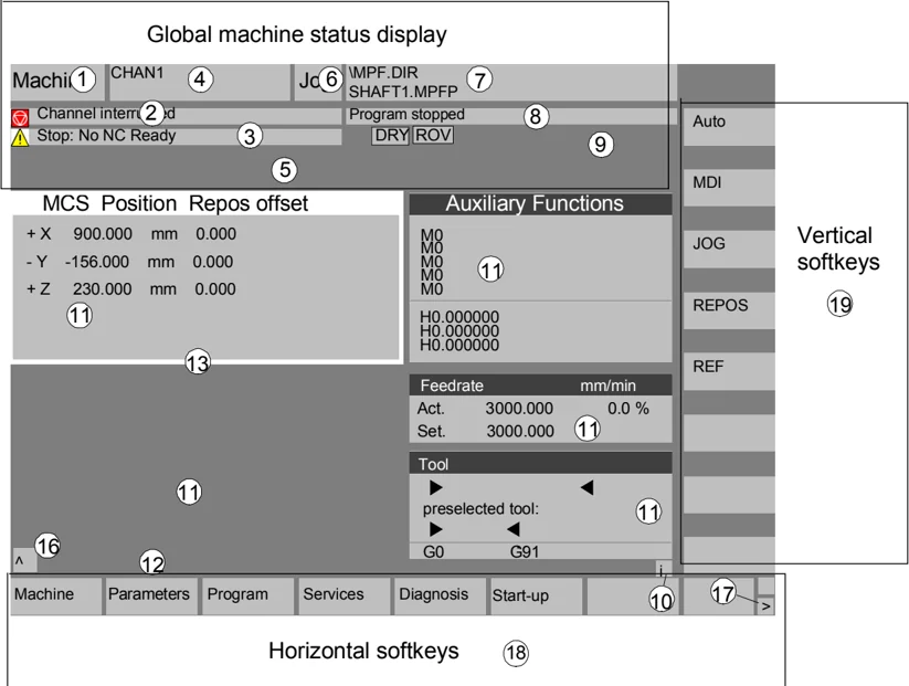
- Operating areas
- Channel status
- Channel operational messages
- Channel name
- Alarm and message line
- Operating mode, submode, (increment if relevant)
- Program name of the selected program
- Program status
- Program control
- Additional information (help)
- i You can display information by pressing the i key
- ^ Recall: Return to higher-level menu
-
ETC.: Expansion of the horizontal softkey bar in the same. Menu
2
Operator Components/Operating Sequences 2.4 Screen layout 2
11 Working windows, NC displays The working windows (program editor) and NC displays (feedrate, tool) available in the selected operating area are displayed here. The unit for positional data is preceded by the diameter symbol Ø in the work pane if the axis is currently the transverse axis and if the tool coordinate system is set. If diameter programming is disabled with DIAMOF, the symbol preceding the unit is no longer visible.
12 User response line with user information Here user information is displayed for the selected function (if available).
13 Focus The selected pane is highlighted by a frame. The window header display is inverted. Data entered on the operator panel front apply to this window.
16 Recall function, i.e., key ^ is active 17 ETC. function, i.e., > key is active 18 Horizontal softkeys 19 Vertical softkeys The softkey functions available in the selected operating area are displayed in the horizontal/vertical softkey bar (corresponding to F1 to F8 on the full keyboard).
Additional information
The screen layout may differ slightly from the layout displayed above, depending on the screen size or resolution used.
2.4.2 Global machine status display
\begin{tabular}{ll} 1 Operating areas & The currently selected operating area is displayed (Machine, Parameters, Program, Services, Diagnostics, Commissioning). \ 2 Channel status & The current channel status is displayed \newline - Channel reset \newline - Channel interrupted \newline - Channel active \ 3 Channel operational messages & For displaying the channel operational messages with symbols: \ \end{tabular}
2 Operator Components/Operating Sequences 01/2008 2.4 Screen layout
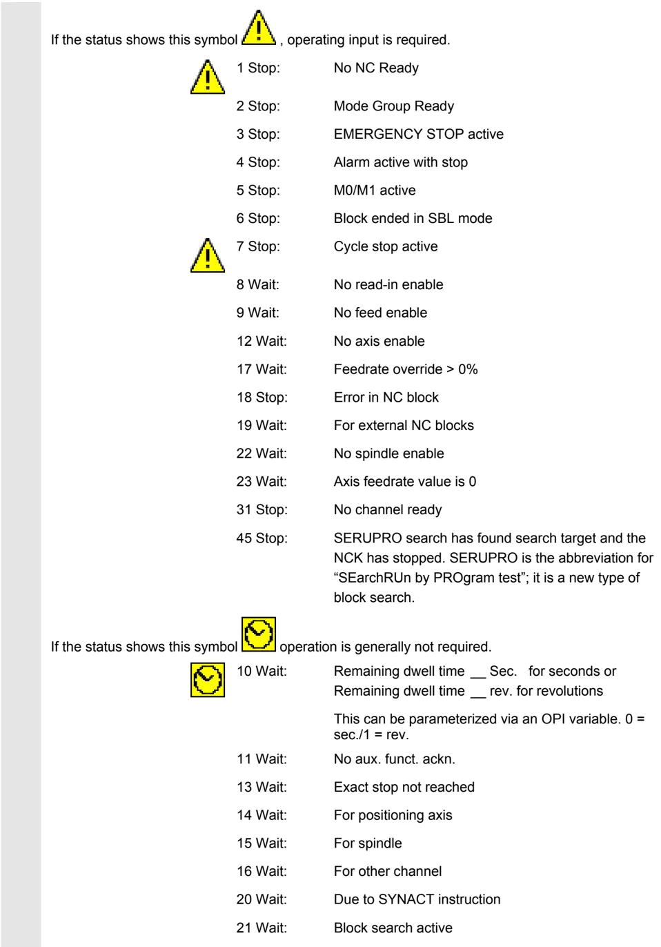
If the status shows this symbol [Warning Symbol], operating input is required.
[Warning Symbol] 1 Stop: No NC Ready 2 Stop: Mode Group Ready 3 Stop: EMERGENCY STOP active 4 Stop: Alarm active with stop 5 Stop: M0/M1 active 6 Stop: Block ended in SBL mode [Warning Symbol] 7 Stop: Cycle stop active 8 Wait: No read-in enable 9 Wait: No feed enable 12 Wait: No axis enable 17 Wait: Feedrate override > 0% 18 Stop: Error in NC block 19 Wait: For external NC blocks 22 Wait: No spindle enable 23 Wait: Axis feedrate value is 0 31 Stop: No channel ready 45 Stop: SERUPRO search has found search target and the NCK has stopped. SERUPRO is the abbreviation for "SEarchRUn by PROgram test"; it is a new type of block search.
If the status shows this symbol [Clock Symbol], operation is generally not required.
[Clock Symbol] 10 Wait: Remaining dwell time __ Sec. for seconds or Remaining dwell time __ rev. for revolutions This can be parameterized via an OPI variable. 0 = sec./1 = rev. 11 Wait: No aux. funct. ackn. 13 Wait: Exact stop not reached 14 Wait: For positioning axis 15 Wait: For spindle 16 Wait: For other channel 20 Wait: Due to SYNACT instruction 21 Wait: Block search active
2-44 ©Siemens AG 2008 All rights reserved.
2 01/2008 Operator Components/Operating Sequences 2.4 Screen layout 2
24 Wait: For tool change acknowledgement 25 Wait: For gear stage change 26 Wait: For position control 27 Wait: For thread cut 29 Wait: For punching 30 Wait: For safe operation 32 Stop: Oscillation active 33 Stop: Axis replacement active (block change inhibited because axis replacement in progress) 34 Wait: For axis container rotation 35 Wait: AXCT axis active as slave axis 36 Wait: AXCT axis active as master axis 37 Wait: AXCT axis changing to follow-up 38 Wait: AXCT internal status change in axis
This delay status may be attributable to the following causes:
- Activation of position control
- Requesting of zero marker
- Reference point approach active
- Parameter block change active
- Measuring system change active
- Measurement on-the-fly active
- Closed-loop controller enable removed
- Status change, axis/spindle disable
39 Wait: AXCT axis drive disable 40 Wait: AXCT axis overlaid motion active 41 Wait: AXCT axis axis replacement active 42 Wait: AXCT axis interpolator active 43 Wait: WAIT_FOR_CC_ENABLE: Waiting for compile cycle 44 Wait: On access to system variable 46 Stop: ESR triggered 47 Wait: Axis container rotation waiting for spindle stop 48 Wait: Axis container rotation waiting for synchronization of MD data (New-Config)
SINUMERIK 840Di sl/840D sl/840D Operating Manual HMI-Advanced (BAD) - 01/2008 Edition 2-45
2 Operator Components/Operating Sequences 01/2008 2.4 Screen layout
49 Wait: For axis replacement: Axis currently coupled 50 Wait: For axis replacement: Lift fast active 51 Wait: For axis replacement: New-Config active 52 Wait: For axis replacement: Axis container rotation active 53 Wait: For axis replacement: Waitp active 54 Wait: For axis replacement: Axis is currently in another channel 55 Wait: For axis replacement: Axis is currently a PLC axis 56 Wait: For axis replacement: Axis is currently an oscillating axis 57 Wait: For axis replacement: Axis is currently a JOG axis 58 Wait: For axis replacement: Axis is currently a command axis 59 Wait: For axis replacement: Axis is currently an OEM axis
 60 Wait: For axis replacement: Axis is currently a slave axis coupled to the master value
61 Wait: For axis replacement: Axis is currently a coupled-motion slave axis
62 Wait: For axis replacement: Axis is currently a coupled slave axis
4 Channel name Name of the channel in which the program is running.
5 Alarm and message line – Alarms and messages or – Instructions that were programmed in the part program using the MSG command (if no alarms are active)
6 Operating mode display The currently selected operating mode, i.e. JOG, MDA or AUTO (automatic) is displayed. The active submode is displayed next to the operating mode. An active increment is also displayed underneath, e.g., JOG Repos 1000
7 Program name Press NC Start to execute this program. The "Program name" output field can be configured for JOG and MDA (see machine manufacturer's specifications).
2-46 ©Siemens AG 2008 All rights reserved.
2 01/2008 Operator Components/Operating Sequences 2.4 Screen layout 2
8 Program status The current status of the part program being executed is output:
- Program aborted
- Program running
- Program stopped
The "program status" output field can be configured, e.g. with the "Channel-wide status display with symbols" function (Subsection 4.1.3 and see machine manufacturer's specifications).
9 Program control display Functions that have been activated can be set via "Program control" so that they are displayed. (See Section 4.6 Automatic mode, "Program control")
2.4.3 Program control display
Function
Functions that have been activated are visible in the program control display (can be set via "Program control", see Subsection 4.6.12). The functions are displayed irrespective of the selected menu.
SKP
Skip block
Program blocks in which the block number is preceded by a slash are skipped when you run the program (e.g. "/N100 ..."). Up to 10 program levels can be hidden (e.g., "/6N100 .."; the 7th program level is hidden)
References: /PG/ Programming Manual Fundamentals, Chapter 2.
SKPn
n = active skip levels
SBL1
Single block with STOP after each machine function block
If this function is active, execution is interrupted after every block that triggers a function on the machine (calculation blocks do not cause an interruption).
SBL2
Single block with stop after each block
If this function is active, the part program blocks are executed as follows: Each block is decoded separately and execution is interrupted after every block.
SBL3
Stop in cycle
If this function is active, the part program blocks are executed individually in the cycle as follows: Each block is decoded separately and execution is interrupted after every block. Part program blocks are
- Traversing blocks
- Switching and auxiliary functions
- Blocks generated internally in the controller (e.g. blocks inserted for tool radius compensation)
- Thread blocks after retraction
- Thread blocks with dry run feedrate
Thread blocks without dry run feedrate are an exception to this. In such blocks, a stop is only performed at the end of the current thread block. SBL2 can only be selected in the Reset state. Either SBL1 or SBL2 can be selected! This function can be activated only in the "Single block" state.
2
Operator Components/Operating Sequences
2.4 Screen layout
2
DRY DRY run feedrate Traverse movements are performed with the feedrate value set in the setting data "Dry run feedrate". This dry run feedrate function replaces the programmed motion commands.
ROV Rapid traverse override The override switch for the feedrate also applies to the rapid traverse feedrate.
M01 Programmed stop 1 When this function is active, processing of the program is stopped at every block in which miscellaneous function M01 is programmed. The message "Stop: M00/M01 active" is then displayed on the screen. Press the NC Start key to resume execution. If the function is not activated, special function M01 (from the part program) is not taken into account.
Additional M fct. Programmed stop 2 When this function is active, program execution on the NC is interrupted on request by the PLC at blocks containing the additional function for a conditional stop.
The machine data 22256: AUXFO_ASSOC_M1_VALUE you can define a function associated with M01. The value of this miscellaneous M function number is then equivalent to a programmed stop 2.
 References
/FB1/Description of Functions - Basic Machine
Predefined Auxiliary Function "Associated auxiliary functions for M0, M1"
DRF DRF selection When the "DRF" function is active, DRF offsets are applied.
PRT Program test If "Program test" is selected, the output of setpoints to axes and spindles is disabled. The setpoint display "simulates" the traverse movements.
FST Feed stop The activated feed stop is displayed. "Feed stop" is indicated in the feedrate window by means of the symbol "Feedrate not enabled" and is omitted from the program control display. This function is not activated/deactivated under Program Control, but via the "Feed Start/Feed Stop" keys on the machine control panel.
2 Operator Components/Operating Sequences
2.5 General operating sequences
2.5 General operating sequences
Keys A range of keys are available in the various operating areas and menus. The function of the keys is the same in all operating areas.
This identical functionality applies only if the operating areas are left intact as supplied by Siemens AG and no modifications have been configured by the user.
Additional information It is possible to customize the menu trees. In this way, users are able to define softkeys according to their individual needs. Due to this capability, the menus and softkeys on your control may be different to those described in this Operator's Guide.
References Commissioning Manual HMI Advanced, see Chapter "Generating user operator menus"
Functions The following section describes functions which you can select in several operating modes.
2.5.1 Program overview and program selection
Function After selection of a workpiece or program overview, individual workpieces or programs can be enabled or disabled for execution.
Sequence of operations "AUTO" mode is selected in the "Machine" operating area. The appropriate channel is selected. The channel is in reset state. The workpiece/program to be selected is in the memory.
An overview of all workpiece directories/programs that exist is displayed. Position the cursor on the desired workpiece/program.
Select the workpiece/program for execution:
©Siemens AG 2008 All rights reserved.
2 01/2008 Operator Components/Operating Sequences 2.5 General operating sequences 2
Program selection The name of the selected workpiece is displayed on the screen in the "Program name" field at the top. The program is then loaded.
2.5.2 Changing the menu window
 If a screen comprises several windows, you can use the "Window selection" key to switch between the individual windows. You only need to do this if you wish to enter data on the operator panel front. The focus changes to the selected menu window (the header and border of the active window appear in a different display format).
Scroll in menu window:
 If the content of a window covers several screen pages, you can use the "Page" keys to scroll up or down through the information. A scroll bar indicates that the content of the window extends beyond the visible display.
Position cursor in menu window:
You can position the cursor at the desired point in the menu window with the "Direction keys".
©Siemens AG 2008 All rights reserved.


2 Operator Components/Operating Sequences 01/2008 2.5 General operating sequences
2.5.3 Selecting a directory/file
The "Direction keys" can be used to position the cursor on the desired directory/file. If you enter a character on the alphanumeric keyboard, the cursor moves to the first name that begins with the character.
Open/close directory: Press the "Input" key to open or close a directory.
Open file: You can open a file with the "Input" key if you wish to edit it in the ASCII editor. The editor is opened automatically.
Select file This key is used to select a file. It is possible to select multiple files. The symbol appears next to the cursor bar when a file is selected.
Select multiple files In order to select a block of files, press the "Shift" and "Cursor down" keys simultaneously.
The first time you press the keys, the start of the block is selected. The subsequent files are selected continuously
until you press the "Cursor up" or "Cursor down" (without "Shift") key.
Deselects a selected file.
Cancels all selections.
2-52 ©Siemens AG 2008 All rights reserved.

2.5.4 Editing inputs/values
If you wish to edit inputs/values, the corresponding key is always displayed automatically on the right of the input field. The following input fields are available:
 1. Option buttons (single selection button/multiple option button):
You can use the "Select" key to activate or deactivate a selection field.
Multiple selector button (you can select several options or none)
Single-option button/option button (only one option can be active at a time)
☑ = active ☐ = not active ● = active ○ = not active
2. Input fields: Position the cursor on the input field and start to type. When you begin typing, you automatically switch to Insert mode.
Confirm your input with the "Input" key. The value is accepted.
To change an existing value, press the "Edit" key to switch to insert mode.
Enter the value or word (e.g. file name, etc.) on the alphanumeric keypad.
In some fields, it is possible to choose between several preset values by means of the "Toggle" key.
3. Selection list Selection lists show you a selected value from a list of possible values.
Press the "Edit" key to open a complete list of possible or existing values.
Position the cursor on the value of your choice using the "Direction" keys.
©Siemens AG 2008 All rights reserved.
2 Operator Components/Operating Sequences 01/2008 2.5 General operating sequences
Always confirm your input with the "Input" key. The value is accepted.
With this key, you can switch to the next value in the selection list without displaying the entire list (e.g. to select from only a small number of values/settings).
- The editor displays only the characters which can be input via the operator panel front keyboard.
- A part program opened by the editor cannot be simultaneously started in the NC (enable is canceled); an alarm (14014) is indicated in this case. If the control is switched off while the editor is open, the enable might have to be set manually.
2.5.5 Confirm/cancel input
Confirm input:
Your inputs are accepted when you press the "OK" softkey. The selected function is executed. The window is closed, and you return to the menu level from which the window was called.
Cancel input:
Your inputs are rejected if you select the "Abort" softkey. The selected function is aborted. The window is closed and you return to the menu level from which the window was called.
This is the same as when returning from a function (vertical softkey bar).
The "Edit" key can also have an "Undo" function if you abandon the input/modification you have just entered. The cursor remains positioned in the currently selected field.
Switch from the horizontal menu level back to the call menu level.
2-54 ©Siemens AG 2008 All rights reserved.
2 01/2008 Operator Components/Operating Sequences 2.5 General operating sequences 2
2.5.6 Edit the part program in the ASCII editor
Function
The ASCII editor provides you with the following functions: – Switch between insert and overwrite mode – Select, copy, delete block – Paste block – Position cursor / find/replace text – Saving a file – Create contour (programming support) – Parameterize cycles (drilling, milling, turning) – Start simulation – Recompile (cycles, free contour programming) – Renumbering blocks – Change settings – 2. Open file
Additional information
A part program selected in the NC can generally only be edited when the channel is in the reset state. When a part program is selected and the relevant channel is in the "Channel Reset" state, the program can be fully edited.
The end of block character is not displayed as " $^L_F$ "; instead it is displayed as "¶".
Please note: It is possible to edit a program both directly in the NC and on the hard disk in the ASCII editor. How programs are saved on the hard disk is determined by settings.
Sequence of operations
The following functions are fully enabled in the Program and Services operating areas but only partially in the Machine operating area. In the Machine operating area, the ASCII editor is called via the program editor, in Services, by selecting a file in the file manager.
You have selected the file you wish to edit in the directory and pressed the "Enter" key, the vertical softkey bar changes. Your selected file is opened in the text editor.

©Siemens AG 2008 All rights reserved.
2 Operator Components/Operating Sequences 01/2008
2.5 General operating sequences
Cursor block: Use the "Direction keys" to position the cursor in the text.
You can page up and down using the "Page" keys.
The character on which the cursor is positioned is deleted.
Press the "Backspace" key to delete the character to the left of the cursor.
Press the "Input" key to end a block. "$L_F$" ("Line Feed") is automatically generated.
Vertical softkeys
Overwrite The cursor toggles between insert and overwrite modes.
Select block When you press this softkey, the vertical softkey bar changes. The softkey marks the beginning of a block. Now position the cursor at the end of the block. The block is selected automatically.
This softkey copies the selected block into the buffer. If a line, which was generated by a support function, is selected the complete support block is copied. It remains stored in the buffer even if another part program is selected.
The selected block is deleted. If a line that was generated by a support function is selected the complete support block is deleted.
Selection mode is canceled when you press "Select block".
Paste block This softkey pastes the cut or copied block from the buffer into the text in front of the cursor position.
©Siemens AG 2008 All rights reserved.


2 01/2008 Operator Components/Operating Sequences 2.5 General operating sequences 2
Find/Go to... The "Find/Go to..." dialog box opens. You can select functions for positioning and searching via the vertical softkeys:
The following search methods are available:
- Search to the beginning of the part program (cursor on the first character in the program)
- Search to the end of the part program (cursor on the last character in the program) and
- Proceed to a particular NC block with "Go to.."
- Or search for a particular character string with "Find".
"Go to...": Enter the block number you are looking for.
- If the line being searched for contains an "N" or ":", you are taken to the block in question.
- A message is output if there is no block with the specified number. Press the "OK" softkey or the "Input" key to position the cursor on the block number/line number of your choice. The "Go to..." window is closed. If you press "Abort" the positioning process is stopped and the window closed.
"Find": Enter the character string you wish to find. The string you enter is sought downwards from the current cursor position, the find result appears as highlighted text. You can start a new search by pressing the "Find Next" softkey or the "Input" key.
Enter the new text with the "Replace" softkey. The text found is replaced by the "replacement text". The new text is replaced when you press "Input". Every time you press "Input", a new find and replace process is started.
Enter the new text with the "Replace All" softkey. The query asks you "Do you really want to replace all non-write-protected strings: ... globally with ... ?". Note: This function can be interlocked with a password (see Commissioning Manual HMI Advanced).
©Siemens AG 2008 All rights reserved.
2 Operator Components/Operating Sequences 01/2008
2.5 General operating sequences
The function "Replace All" is only enabled for files located on the hard drive (i.e., not in the NC memory).
If you press "Abort", the Find + Replace process is stopped and the window closed. You are back in "Edit mode" again".
Save File Changes are saved in the file loaded in the editor.
Additional information Please note that the changes to programs stored in the NC memory take immediate effect. The save options for the control system can be altered in the "Settings" menu (e.g., save automatically, etc.). (See Chapter "Startup")
Close editor When you select the "Close editor" softkey, a dialog box may appear in which you must confirm whether or not to save the changes. The text editor is then closed and the current program overview is displayed again.
Horizontal softkeys
Free contour programming Use the "Contour" and "Generate contour" softkeys to call up the free contour programming function.
The part program block is inserted in the part programs with the appropriate parameter settings.
Cycle parameterization The following programming support functions are available:
- Drilling, milling, turning (cycles)
- Contouring (free contour programming)
You can call up the relevant cycle parameter settings via the Drilling, Milling, Turning vertical softkeys.
Enter the new values for the cycle parameters.
The part program block is inserted in the part programs with the appropriate parameter settings.
Example: CYCLE81 (110, 100, 2, 35)
Abort
Save file
Close editor
Contour Generate contour
Accept contour
Drilling Milling
Turning
OK
©Siemens AG 2008 All rights reserved.
2
Operator Components/Operating Sequences
2.5 General operating sequences
 References
/PGC/, Programming Guide Cycles
Simulation
Simulation
The simulation is called (see /BA/, Operator's Guide, Interactive programming or Chapter 6 Program operating area). The "Simulation" softkey is displayed only if the simulation function can be called in the current operating situation.
Recompile
If program steps (cycle/contour) have already been parameterized but must be changed, you can display and edit the parameter values with their meanings. Position the cursor in the text editor on the line with the program step (contour/cycle) whose parameters you wish to change. A screen form containing the parameter settings for the selected cycle/contour appears on the screen.
▼
Recompile
Change the parameters.
OK
The part program block is automatically inserted in the part program with the new parameter settings.
Renumber
The block numbering in the program shown in the editor is executed again according to the values defined under the "Settings" softkey.
When using cycle support in the part program, additional comment lines are generated in front of and behind the cycle call and used for recompilation. These lines start with ;# ... . When cycles are called that were directly recorded with the editor (or even when "old" cycles are called), this information is missing. The ;#-lines, which are the additions required for screen form support, are generated during recompilation of these cycle calls. As a result, the length of the part program is expanded by a number of lines.
 References
Commissioning Manual HMI-Advanced: "Expand User Interface" (BE1)
©Siemens AG 2008 All rights reserved.
2 Operator Components/Operating Sequences 01/2008 2.5 General operating sequences
Settings Define the following values in the "Editor Settings" window:
- Horizontal scrolling ON/OFF
- Display hidden lines ON/OFF
- Deactivate LF in program If this setting is selected, a space is displayed in the editor window on the screen in place of the linefeed character. In the file to be edited, the linefeed character is retained.
- Time interval for Automatic Save When you set Automatic Save, you can also set the time intervals at which text must be saved automatically (applicable only to files on hard disk). If a value \neq 0 is entered, the "Save file" softkey is not displayed. If the value 0 is entered, automatic save is not performed.
- Automatic numbering ON/OFF A new block number is automatically inserted on every new line. If you wish to assign new block numbers to an existing program, use the "Renumber" function.
- Number of first block
- Incrementation of block numbers (e.g. 1, 5, 10)
Setting contour The following settings are possible for contour programming:
- Last line Each time you complete a program step in the contour programming you can insert a text in the last line (e.g., "End of contour").
Additional information
- The coordinate system and the technology to be used are set via the machine data; see Commissioning Manual HMI Advanced.
- Edited programs are automatically enabled after saving.
 ©Siemens AG 2008 All rights reserved.
2 01/2008 Operator Components/Operating Sequences 2.5 General operating sequences 2
2.5.7 Switching over the channel
Function
It is possible to switch between channels when several are in use. Since individual channels may be assigned to different mode groups, a channel switchover command is also an implicit mode switchover command.
If the selected channel is linked to another NCU (M:N link), the HMI Advanced is also switched over implicitly to the relevant NCU.

When a "Channel menu" is configured, all existing communication links to other NCUs plus the associated channels are displayed on softkeys.
Channel states
The following three channel statuses can occur in each mode:
- Channel reset The machine is in the initial state, e.g., after power-on or after end of program. The initial state is defined by the machine-tool manufacturer in the PLC program.
- Channel active. A program has been started, the program is being executed or a reference point approach is in progress.
- Channel interrupted The running program or reference point approach has been interrupted.
In this context, a program can be a main program, subprogram, cycle or a series of NC blocks.
There are 3 different switchover levels:
- Switch to next channel.
- Switch over configured channel group/channels (1 NCU).
- Switch to another NCU (with M:N link involving several NCUs).
©Siemens AG 2008 All rights reserved.
2 Operator Components/Operating Sequences 01/2008 2
2.5 General operating sequences
2.5.8 Packet calculator
Prerequisite: The cursor is positioned on an input field or input/output field.
Equal key Switch to pocket calculator mode. In this state, if you enter a basic arithmetic symbol (+, -, /, *) followed by a value (e.g. 13.5) and
then press the input key, the next value entered is calculated with the preceding value. If the input/output field is opened with the input or equal key, the editor is in insert mode; if the field is opened directly with a character, the editor is in overwrite mode.
Inch/metric conversion In pocket calculator mode, you can convert numeric values from the metric to inch system by entering "I" and from the inch to metric system by entering "M".
Proceed as follows to convert values:
- Position the cursor on an input field which contains a numeric value or enter a numeric value
- Press the equal key
- Enter the letter "I" (convert to inches) or "M" (convert to metric)
- Press the "input" key, the value is converted.
2.6 Calling the help function
Function

Whenever the help symbol appears in the user response line, this means that additional information can be called via the Help key. A comment appears in the user response line or a dialog box opens.
If, for example, you have made an input error, you can select the HMI Help to access detailed information about the error that has just occurred, e.g. the Diagnostics guide is displayed.
Available help functions include:
- Alarm help: Detailed information about the alarm or message displayed
- MD help: Detailed information about the selected machine data or setting data
- Editor help: Brief information or, if the key is pressed again, detailed information about the command or function indicated by the cursor position.
Sequence of operations
Pressing the "Information" key, e.g., in the "Diagnostics" operating area, automatically calls and displays HMI Help information for a currently pending alarm.
You can page through the document with the softkeys "Page up" and "Page down",
you jump to the next hit in the document with "Next entry".
Where there are cross-references to other documents, you can jump to a particular point in that document with this softkey.
You can search for any words in the document with the search function "Go to ...".
With the softkeys "Zoom +" and "Zoom -" you can increase or decrease the zoom factor in the document view.
By pressing "Exit help", you can return to the editor.
2 Operator Components/Operating Sequences
2.6 Calling the help function
In some cases, help is provided in a similar manner to Windows Help by pressing the following softkeys:
-
Page up / Page down
Press the "Page down" or "Page up" softkey.
The display scrolls up or down by a whole page. -
Selection back / Selection fwd.
Use the "Selection fwd" or "Selection back" softkeys to go to the entry of your choice. -
Follow cross ref.
Press the "Follow cross-ref." softkey.
The required entry appears on the screen. -
Back
Press the "Back" softkey to return to the previously displayed entry. -
Contents
Select and display an entry in HMI Help:
Press "Contents" softkey.
The current contents of HMI Help are displayed.
You exit the HMI Help and return to the previous menu. -
Exit help
Context-independent Help call:
Press the following keys to call “HMI Help” directly:
“Menu Select” key
Followed by “ETC” key
HMI Help

©Siemens AG 2008 All rights reserved.
2
Operator Components/Operating Sequences
2.6 Calling the help function
2
2.6.1 Editor help
Function
The following help functions are available as programming support for editing part programs in the editor via the "information" key:
-
Quick help on program commands For configuring, see Commissioning Manual HMI-Advanced : "Help in the editor" (HE1) – Help in part program for instructions: Display descriptive text (e.g. G9 "Exact stop - deceleration") – Display an overview of topics (e.g. "Preparatory functions", "Path commands", "Path traversing behavior", etc.), to which instructions are assigned. – Display an overview of instructions with descriptive text – Search selectively in special screen forms on the basis of topic assignment or by entering a character string – Transfer the selected instruction to the editor
-
Quick help "Parameterization form" + extended help "pdf" Configurable parameterization forms from which you can jump to a particular page in the documentation (pdf file), e.g., parameterization forms for cycles, jump to Programming Guide Cycles: For configuring, see Commissioning Manual HMI-Advanced: "Expand User Interface (BE1)".
-
Quick help for program commands + extended help "pdf". From the context-sensitive help you can jump to the corresponding page in the documentation with the "information" key, e.g. jump to Programming Guide Fundamentals.
©Siemens AG 2008 All rights reserved.