7 01/2008 Services operating area 7.3 Data selection 7
7.3 Data selection

Function
Using the "File selection" softkey, you can choose the directories that you wish to have displayed in the "Services" area.
The directories can be selected for two different access levels:
- Users
- Maintenance
\begin{tabular}{|l|c|c|} \hline Data selection & \multicolumn{2}{c|}{Default setting} \ \cline{2-3} & Users & Maintenance \ \hline User cycles & X & X \ Display machine data & & \ Logs & X & X \ Processing sequence (job sequence) & & \ Data storage & & \ Definitions & & \ Diagnostics & & \ Interactive programming & & \ Manufacturer cycles & & \ MSD data (status data) & & \ Commissioning & & \ Comments & & \ MBDDE alarm texts & & \ NC active data & & X \ NC data backup & & \ OEM data & & \ Standard cycles & & \ System & & \ Part programs & X & X \ Templates & & \ Subprograms & X & X \ FDD data (status data) & & \ Workpieces & X & X \ Tool management & & X \ Clipboard & & X \ \hline \end{tabular}
SINUMERIK 840Di sl/840D sl/840D Operating Manual HMI-Advanced (BAD) - 01/2008 Edition 7-373

7 Services operating area 01/2008 7
7.3 Data selection
Keywords/directories in the hierarchical file structure
The different files are made available for transfer under the following directories:
- Data (general)
- Option data
- Machine data (all, NC MD, channel MD, axis MD)
- Setting data
- Tool offsets
- Zero offsets
- Global user data
- R parameters
- Commissioning data
- NCK data
- PLC data
- Compensation data
- Leadscrew pitch/encoder error
- Quadrant errors
- Sag/angularity
- Display machine data
- Workpieces
- Part programs
- Subprograms
- User cycles
- Standard cycles
- Comment data
- Definitions
- Feed drives (FDD)
- Main spindle drives (MSD)
- OEM data
- System data (NC)
- Logbook
- Communication error log
If your control includes additional directories, these can be found in the file tree.
7-374 © Siemens AG 2008 All rights reserved.
7
Services operating area 7.3 Data selection
Sequence of operations
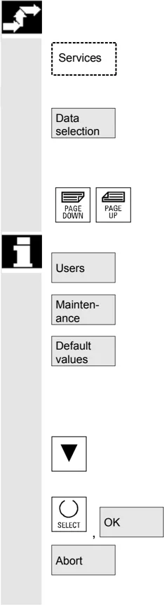
The "Services" operating area is selected.
Press the "Data selection" softkey. The "Data selection for display" window is opened. The vertical softkey bar changes.
You can page through the window using the "Page" keys.
You can toggle between the settings
- Users
- Maintenance
- Default values
The "Default values" softkey assigns default values to the settings "User" or "Maintenance". These are suitable defaults that are supplied in the software.
Select, for example, the "User" setting. Position the cursor on an additional directory.
Mark the directory of your choice and press the "OK" softkey.
A reset command by means of the "Abort" softkey for the selected access level resets the data selection.
Additional information
The file tree displays files that the user may view on the basis of his or her access rights.

7 Services operating area
7.3 Data selection
7.3.1 Special directories and memory areas
The following directories contain special files:
Clipboard The clipboard is a directory on the hard disk, where files, which cannot be included in the copy target directory, are stored. This may be the case for example, if their file type is unknown, or is not permitted in the copy target directory or if the reading process is canceled (e.g., on USB memory media).
Archive If you wish to save several files, you can store them in an archive file (.ARC). The source path for the files, which are to be stored in the archive file, is also saved. This allows the packed file to be transferred back to the same directory from which it was copied when the archive file is unpacked again. Series commissioning archives are also stored in this directory.
USB memory The SIMATIC USB FlashDrive has been released for SINUMERIK.
NC active data
The NC memory contains data (e.g. R parameters, tool offsets, machine data) that are not stored there in file format. The directory "NC active data" is provided in the file manager to allow the user to access these data and store them on the hard disk in file format.
If the user wishes to save data in files on the hard disk, they can set up the same directory structure under a directory of any name for "NC data" (.MDN). Via "Copy/paste" any active data can be fetched from the NC and stored in files on the hard disk.
NC-active data cannot be unloaded.

7.3.2 Data on the hard disk
Function
General In addition to the NC working memory, SINUMERIK controls with HMI are provided with a hard disk. It is thus possible to store all data or programs which are not required in the NC on the hard disk. All data are displayed in a single file tree on the user interface.
In the "Services" operating area, all files on the hard disk and in the NC memory can be:
- Managed (new, load, unload, copy, delete, change properties),
- Saved for a series commissioning (NC, PLC and HMI data) and
- Downloaded to the NC memory (programs and files).
Copy to diskette When you copy to diskette the full file names are stored on the diskette.
Additional information
The end of block character is displayed not as "L_F" but as "¶".
System queries The system behavior when copying/creating data (e.g. overwrite existing files or query first) can be configured for all operating areas.
Query dialogs "Save as" In the "Commissioning" operating area, press the HMI/System settings/Query softkeys to specify that a dialog box is to appear before files are overwritten. Otherwise, the files are overwritten without prompting or a copy is created.

7 Services operating area 01/2008 7
7.3 Data selection
Query dialog
Copy file from hard disk:
- The file exists on hard disk and is overwritten when you select "OK" if the name/data type is to remain unchanged!
- The file exists on hard disk. When you select "OK" a copy is created if the name/file type is to remain unchanged!
Copy file from NC memory:
- The file exists on the NCK and is overwritten when you select "OK" if the name/data type is to remain unchanged!
- The file exists on the NCK. When you select "OK" a copy is created if the name/file type is to remain unchanged!
Copy a workpiece:
- The workpiece already exists. When you select "OK" a copy of the workpiece is created if a new name is not specified!
Copy a directory:
- The directory already exists. When you select "OK" the contents are overwritten if a new name is not specified!
- The directory already exists. When you select "OK" the contents are overwritten if the directory with a fixed data type cannot be changed.
Copy a file of data type main program (MPF):
- The file cannot be created at this location under its original "main program" data type!
Vertical softkeys for "Save as"
All without prompt Press the "All without prompt" softkey if all existing files in the current directory are to be created with new names without a "Save as" dialog. All files for which the original file type can be created are automatically converted to the specified data type.
S kip file Press the "Skip file" softkey if the copy operation is to be continued with the next file.
Abort This key cancels the entire copy operation.
OK An existing file is either overwritten or, if the name or file type was changed, saved with the new name. The "OK" softkey is disabled if you have to enter a new name.
Display The file tree display can be modified by the user:
- Display of file properties
- Number of displayed directories
7
Services operating area 7.3 Data selection
7
Data storage
Data management directories:
- Workpieces
- Part programs
- Subprograms
- User cycles
- Standard cycles
- Manufacturer cycles
Limit of data management
A total of 100,000 files can be stored in all data management directories, but the number of files in each directory (each *.WPD workpiece directory for workpieces) is limited to 1000 files. Files in other directories do not count toward the total limit of 100,000 files. However, each of these directories is also limited to 1000 files, e.g. a maximum of 1000 archives in the archive directory. Network drives are also limited to a maximum of 1000 files in each directory.
In practice, the number of files available also depends on the file sizes and the available memory space. A large number of files slows down the display generation for directory displays.

7 Services operating area 01/2008 7
7.4 Transfer display MD from HMI Embedded
Function
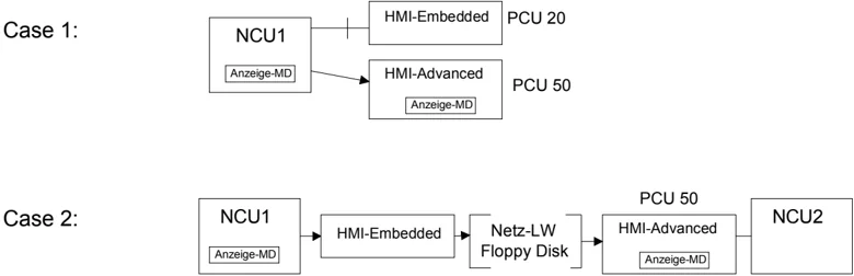
Usage When migrating from the HMI component HMI Embedded (PCU20) to HMI Advanced (PCU50/PCU70) you may like to transfer tried and proven display machine data from the HMI Embedded configuration to the HMI Advanced configuration, e.g. for use with ShopMill/ShopTurn. The following section describes how to proceed for to transfer the machine data.
Starting point Display machine data reside on the NCU for HMI Embedded, and on the hard disk of the PCU50/PCU70 for HMI Advanced.
Case 1:

Case 2:

Sequence of operations
The transfer consists of two steps:
- Copy the display machine data with HMI Embedded
- Read into the PCU50/PCU70 under HMI Advanced
Case 1 acc. to diagram On the HMI Advanced system: Services operating area Transfer display machine data to the display if not yet activated: Services \rightarrow Select data Select "Display machine data" OK Copy display machine data: Services \rightarrow Manage data Display machine data\BDxxyy.tea Copy
7.4 Transfer display MD from HMI Embedded
Target directory Select the target directory Diagnostics\MachDat\OperatorPanel Paste
Activate inserted display machine data via Commissioning: Commissioning → Machine data → Display MD → File functions Set up directory and file BDyy.tea →Load
Additional information
HMI Embedded manages more display machine data than HMI Advanced. An entry is made in the error log for each proposed display machine data that is not defined in HMI Advanced or contains an error.
Case 2 acc. to diagram Transfer display MD to floppy disk or network drive: On the HMI Embedded system: Program → ETC → Set up operator data BDx.tea →Copy → ETC Select destination medium: Network drive or floppy disk Paste
On the HMI Advanced system: Services → Manage data Select transfer medium: Network drive or floppy disk Select BDxxyy.tea →Copy Continue as for the 1st case, destination directory, see above.
7 Services operating area
7.5 V.24 interface
7.5 V.24 interface
7.5.1 Parameterizing the V.24 interface
Function
Parameters for DIN programs
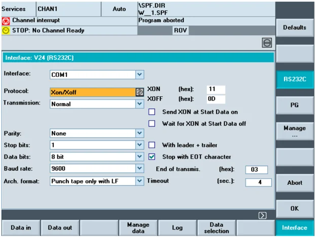
Default: V.24 user Interface: COM1 Protocol: RTS/CTS Parity: None Stop bits: 1 ☐ With header and trailer labels Data bits: 8 ☑ Stop with end of data transfer character Baud rate: 9600 Archive format: Punched tape with ... time monitoring (sec.): 04 With this setting, programs according to DIN are downloaded (starting with %) or output.
Parameters for archiving with PG/PC
Default: V.24 PG/PC Interface: COM2 Protocol: RTS/CTS Parity: Stop bits: 1 Data bits: 8 Baud rate: ≥ 9600 Archive format: Binary format (PC format)
7 01/2008 Services operating area 7.5 V.24 interface 7
This setting allows files to be archived and downloaded in the SINUMERIK 840D PC format. When transferring MSD, FDD files, it is not permissible to select “stop with end of data transfer character”. Other settings are also possible for ASCII data. These must match those set at the PG. The 6FX 2002-1AA01- cable is intended for this purpose.
Protocol
If V.24 data transfer starts, “Services” outputs status messages in the dialog line indicating the data transfer status. These messages are as follows: “Wait for CTS signal” “Wait for DSR signal” "Wait for Xon character" "Data transfer active"
The following protocols are supported for transfer using V.24,
- Xon/Xoff and RTS/CTS,
- Software Flow Control and Hardware Flow Control
- Xon/Xoff (handshake)
For V.24 data transfer, the modes wait for Xon to receive and send Xon to send data can be set under “interface”. The default setting is H11 or H13. One possibility of controlling data transfer is to use the control characters Xon (DC1, DEVICE CONTROL 1) and Xoff (DC3). If the buffer of the peripheral device is full, it sends Xoff, as soon as data can be received again, it sends Xon (= default setting).
Transfer
It is also possible to use a secure protocol for data transfer (ZMODEM protocol).
Normal/secured
For the selected interface, secure data transfer is set in conjunction with handshake RTS/CTS. “Normal data transfer” is the default setting
The protocol setting is requested for:
- Data input/output
- Series commissioning/upgrade in conjunction with V.24 or PG The SinuCom PCIN software is required as partner on the external PC/PG.
SINUMERIK 840Di sl/840D sl/840D Operating Manual HMI-Advanced (BAD) - 01/2008 Edition 7-383

7 Services operating area 01/2008
7.5 V.24 interface
Baud rate Input: By selecting using the selection key in the "Interface" screen under "Baud rate" 300 baud 600 baud 1200 baud 2400 baud 4800 baud 9600 baud 19200 baud (default setting) ... 115200 baud Data transfer rates of up to 115 kbaud can be selected. The baud rate that can be used depends on the connected device, the cable length and the general electrical conditions.
Data bits Number of data bits with asynchronous transmission Input: By selecting, in the "Interface" screen under "Data bits"
- 8 data bits (default setting)
- 7 data bits
Parity Parity bits are used for error detection: The parity bits are added to the coded characters to make the number of positions set to "1" an uneven number (uneven parity) or to an even number (even parity).
Input: By selecting, in the "Interface" screen under "Parity"
- No parity (default setting)
- Even parity
- Uneven parity
Stop bits Number of stop bits for asynchronous data transfer Input: By selecting, in the "Interface" screen under "Stop bits"
- 1 stop bit (= default setting)
- 2 stop bits
7-384 © Siemens AG 2008 All rights reserved.

7 01/2008 Services operating area 7.5 V.24 interface 7
Special Functions The following special functions are additionally possible; these can be enabled in the interface screen. If the field has a check mark, this means: Special function active.
Stop with end of data transfer character Active: Text mode: The end of data transfer character is active. Inactive: Binary mode: The end of data transfer character is not evaluated. The default setting for the end of data transfer character is 03 (ETX) hexadecimal.
With header and trailer labels Active: When entering overread header label - for output, output 120x0(hex) (feed before and after the data). Inactive: Header and trailer labels are read-in.
When output, no header label of 0(hex). Download is automatically recognized. The following archive formats are available:
- Binary format (PC format)
- Punched tape format with LF
- Punched tape format with CR LF
Time monitoring (always) Active: For data transfer problems or at the end of data transfer (without end of data transfer character) data transfer is interrupted after the specified number of seconds. The time monitoring is controlled by a time generator (clock) that is started with the first character and is reset with each transferred character. Inactive: Data transfer is not interrupted. The time monitoring can be set (seconds).
Saving V.24 interface settings V.24 interface settings can be saved in separate files in the V.24 DIR directory. The parameters in a file can, as a whole, be assigned to one of the interfaces. Additional functions are available to manage/update these files.

7.5.2 Using the V.24 interface
Function
V.24 interface
You can output files to an external device or download files from there via the V.24 interface. The V.24 interface and your device must be matched with one another. The control provides you with an appropriate input screen form in which you can define the specific data for your device.
Vertical softkey bar
For each V.24 interface, you can define a parameterization:
- V.24
- PG/PC
Sequence of operations
“Interface” softkey
Press the "Interface" softkey. The vertical softkey bar changes. Select the interface that you wish to parameterize.
“Standard values” softkey
The default values for “V.24 interface” or “PG interface” are accepted, depending on which interface has been selected for parameterization. If a file has been assigned to the interface, then this assignment is cancelled. The file name is removed from the softkey.
"V.24" softkey
V.24 (default setting): If a parameter file is assigned to the current interface, then instead of V.24, the name of this file is displayed.
“PG” softkey
Programming device/PC: If a parameter file is assigned to the current interface, then instead of the PG, the name of this file is displayed.
"Manage" softkey
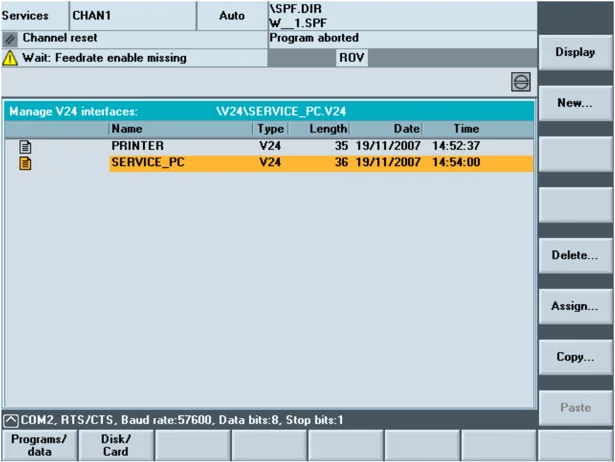
An additional screen form can be selected with which V.24 parameter files can be set-up, deleted, copied, assigned and displayed.
Refer to the Manage sub-item
“Abort” softkey
Back to the previous screen form
7
Services operating area 7.5 V.24 interface
7
"OK" softkey
The actual settings are activated and saved in the parameter file. If a parameter file name is displayed in the header line, then the displayed interface parameters are saved in this file. Saving in a file with the "Interface": None" setting is rejected with an error message. The settings are activated for the actual interface if a file name is not displayed in the header line or if this file is assigned the actual interface.
Refer to the Manage sub-item
The V.24 interface dialog box is accessed, if:
- A V.24 parameter file was selected in the "Services" main screen and was acknowledged using the "Input" key.
- The "Interface" softkey was pressed in the "Services" main screen. In this case, the parameters of the V.24 and PG interfaces are available for processing as before. The interface parameters are saved independently of the V.24 DIR directory.
Manage
"Display" softkey
The parameters of the selected V.24 parameter file are displayed in the "V.24 interface" screen. The file name is displayed in the header line of this dialog box.
"New..." softkey
After entering a file name (max. 10 characters) the actual V.24 parameters are written to a new file in the V24.DIR directory.

7.5 V.24 interface
“Delete...” softkey
After being acknowledged by the user, the selected V.24 parameter file is deleted. If a file that is assigned to an interface is deleted, then its file name is also removed from the interface softkeys.
“Assign...” softkey
A V.24 parameter file is assigned to the actual interface in a dialog box. The associated parameters are activated and the file name is displayed on the corresponding softkey (instead of V.24 or PG). The status line shows the parameters saved in the file. The actual interface for the assignment can be temporarily modified using the vertical softkeys.
"Copy..." softkey
- After entering a new name (max. 10 characters), the actual V.24 parameter file is a) copied into the V24.DIR directory or b) by pressing the “floppy disk” softkey is saved on floppy disk, or c) by pressing the “clipboard” softkey is copied into the clipboard
- If several files are selected at the same time, then only copies on the floppy disk or the clipboard can be activated When copying to floppy disk or the clipboard, it is not possible to assign a new file name.
Status line
The following data is displayed in the status line associated with the currently selected parameter file:
- COM1 or COM2
- Xon/Xoff or RTS/CTS
- Baud rate
- Number of data bits
- Number of stop bits
Return jump to the “Interface: V.24” dialog box
Error handling
Only V.24 parameters with the entries Com1 or Com2 can be saved in the field "Interface:".
If an error is detected when displaying/assigning a V.24 parameter file, then its file name is displayed in the screen interface: V.24 in the header line.
Cancel assignment
If a “none” is in the screen “Interface: V.24”, interface field: and if a V.24 parameter file is assigned, then the assignment is cancelled when OK is pressed.

7 01/2008 Services operating area 7.5 V.24 interface 7
Booting After booting, the assigned files are displayed on the V.24 PG softkeys and their settings for the interfaces are activated. If the assigned files are not found, then the standard texts are re-displayed (V.24 or PG). The corresponding interface is then assigned with the last V.24 parameters.

7 Services operating area 7.5 V.24 interface 7
Notes
Diagnostics operating area
8.1 Diagnostics main screen 8-392
8.2 Remote diagnostics 8-394
8.3 Alarms and messages 8-394
8.4 Service displays 8-396
8.4.1 Service axis 8-398
8.4.2 Service drive 8-399
8.4.3 Service SI (Safety Integrated) 8-400
8.4.4 Systemressourcen anzeigen 8-412
8.4.5 Configuration data output 8-413
8.4.6 Communication error log 8-413
8.4.7 Action log 8-414
8.5 Calling theversion screen 8-414
8.5.1 Sorting and saving version data 8-415
8.5.2 Display the version screens for cycles 8-416
8.5.3 Cycle version output 8-419
8.5.4 Displaying loadable compile cycles 8-419
8.6 Interrogating the PLC status 8-421
8.6.1 Changing/deleting a value 8-422
8.6.2 Assign symbolic PLC addresses 8-423
8.6.3 Select operand screens for PLC status 8-428
8.6.4 File functions 8-429
SINUMERIK 840Di sl/840D sl/840D Operating Manual HMI-Advanced (BAD) - □□/□□□□ Edition
8 Diagnostics operating area 01/2008
8.1 Diagnostics main screen
8.1 Diagnostics main screen
A display headed "Alarms" appears when you select the “Diagnostics” operating area.
Main screen
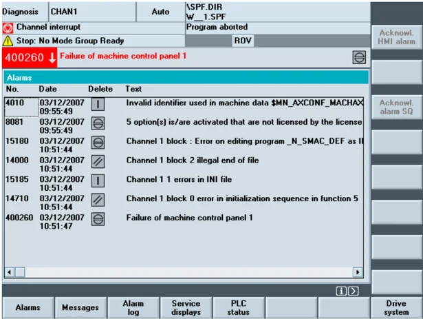
Number The alarm number is output under "Number". The alarms are output in chronological order.
Date The date and time at which the alarm occurred is displayed with the date, in hours, min, sec.
Clearing criterion The symbol denoting the alarm abort key is displayed for every alarm.
Text The alarm text is displayed under "Text".
Horizontal softkeys
Alarms All active alarms are displayed in the "Alarms" display.
Messages An overview of active messages is displayed.
8
Diagnostics operating area
8.1 Diagnostics main screen
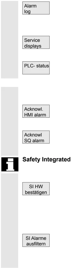
\begin{tabular}{ll} Alarm log & The alarm log of alarms and messages that have occurred is displayed. The log also includes alarms that have already been reset. Default setting for the alarm buffer: 150 alarms/messages \ Service displays & You can view updated information about axes and drives installed in your system under the "Service displays" softkey. \ PLC- status & Information on the current status of the PLC memory locations. \ \multicolumn{2}{l}{\textbf{Vertical softkeys}} \ Acknowl. HMI alarm & HMI alarms (alarm number 120...) that have occurred can be acknowledged. \ Acknowl SQ alarm & SQ alarms (PLC alarms) that have occurred can be acknowledged. \ \multicolumn{2}{l}{Safety Integrated} \ & If the "Safety Integrated" option is active, in addition, the two following softkeys are available in the "Alarms" main screen: \ SI HW bestätigen & This softkey is only displayed if new hardware is found. Message 27035 is then output with the request to acknowledge the new hardware components and to perform a function test (this depends on the access level: As a minimum, key-operated switch position 3 is required). \ SI Alarme ausfiltern & After this softkey has been pressed, the display of SI alarms is filtered-out and suppressed in the "Alarms" window. The SI alarms are still displayed in the header. \ \end{tabular}
8 Diagnostics operating area
8.2 Remote diagnostics
8.2 Remote diagnostics
The control can be operated externally over a remote connection (e.g. modem) The ePS Network Services software is installed with HMI-Advanced. The program is started using the "ePS Network" softkey when selecting the operating areas.
For further information about remote diagnostics, please refer to:
- Function Manual: ePS Network Services
- /FBFE/ Description of Functions: Remote diagnostics
8.3 Alarms and messages
Function
You can display a list of alarms and messages and acknowledge them.
Sequence of operations
Alarms: The alarm overview displays all active alarms with alarm numbers, date, clearance criteria and descriptions. Clear the alarm by pressing the key that is displayed as a symbol: Switch device off and on again (main switch) or NCK POWER ON
Press "Reset" key.
Press "Alarm Cancel" key.
Alarm is cleared by "NC Start".
Alarm is cleared with the "Recall" key.
Messages: PLC operational messages that do not have to be acknowledged (as standard) (configurable).
ePS Network
References
Alarms

 Reset
 ALARM
CANCEL
 Cycle Start

Messages

8
Diagnostics operating area 8.3 Alarms and messages 8
Alarm log: A log containing the alarms and messages that have so far occurred is displayed. 150 alarms/messages can be logged as standard.
It also contains the alarms that have already been acknowledged.
This symbol means "Alarm is still active".
The alarm is updated (static display).
By pressing this softkey, the current status of the log is stored in the displayed path and can be archived from here as required.
Changing the chronological sorting sequence of the alarms in the display.

Acknowledgement symbols The following acknowledge symbols apply to the HMI and PLC alarms:
HMI alarms
PLC alarms
Safety alarms S
Safety alarms SQ
The SQ alarms are cleared with the "Acknowledge SQ alarm" softkey. The S alarms are display alarms; they do not have to be cleared. The way S and SQ alarms are displayed depends on the settings in the files "MMC.INI" and "MBDDE.INI".
You can determine which acknowledgment symbol is to be displayed for the PLC alarms by an entry in the INI file "DG.INI".
These symbols are available for PLC alarms.
or
References Activation of the symbols is described in: Commissioning Manual HMI-Advanced (IM4)
8.4 Service displays
Function
When commissioning digital drives and diagnosing faults, the various operating states of individual machine axes can be visualized with a type of traffic light indicator in the "Service overview" display, which you can open from the "Service display" menu.
Service Overview
This overview shows specific enable signals and statuses for each of the available axes 1 to 31. Up to 6 different states can occur on each axis:
Columns for machine axes 1 to 31
Differentiating features of the traffic light indicator for each axis:
- Green: The axis is behaving normally.
- Yellow: The axis is not ready.
- Gray: The axis is not affected.
- Red: An alarm is pending for this axis.
- Line: No drive assigned to axis.
- Special characters: Error when reading the data, e.g., if date not available.
Rows with the drive diagnostic functions
Drive enable (terminal 64/63)
Pulse enable (terminal 64/48)
Pulse enable (term. 663 / SI: drive relay)
Setup mode (terminal 112)
PLC pulse enable
Speed controller enable NC
DC link status
Enable pulses
Drive ready
Heatsink temperature warning
Power section in i2t limitation
Motor temperature warning
Measuring system 1 active
Measuring system 2 active
8
Diagnostics operating area 8.4 Service displays
8
Sequence of operations
Service displays
Select the menu "Service displays". The softkey bars change. The softkeys in the horizontal menu bar allow you to select the various service displays. The vertical softkeys are context-sensitive according to the service display. You can use them to select the axis configuration or define or change a specific axis selection.
Change selection...
Define a specific axis selection
Press the "Change selection..." softkey in the "Service overview" window.
Change configurations
You can compose your own axis list in the "Change configurations" menu. The available axes can be entered in the axis list in any order. Example: 4 axes should appear in the order 1 3 5 8. The existing axis list appears in "Change configurations", e.g. 1 7 5 Use the "Insert" key to enter the new axes with a space between each axis number: 1 3 5 8
INSERT
Axis numbers outside the valid range from 1 to 31 are deleted. A default list ("1 2 3 4") is displayed if you try to enter an empty list.
Abort
Returns you to the main "Service overview" menu: the changes to the current axis list are not saved.
OK
Returns you to the main "Service overview" menu: the changes to the current axis list are saved and applied with the displayed information.
Selected axes
Display selected axes
Press the vertical softkey "Selected axes". The window changes to the main "Service overview" menu and the previous axis selection is displayed.
Active axes
Display active axes
Press the "Active axis" vertical softkey in the "Service overview" window. The active axes appear in the main "Service overview" menu.
All axes
Display all axes
Press the "All axes" vertical softkey in the "Service overview" window. The maximum set of possible axes appears in the main "Service overview" menu.
