6 "Program" operating area 01/2008 6
6.4 Structured step sequence display (option)
This ensures that an existing program can be displayed in steps without intervention.
If you wish to store your own icons or use existing ones, please contact your machine supplier.
Switch view
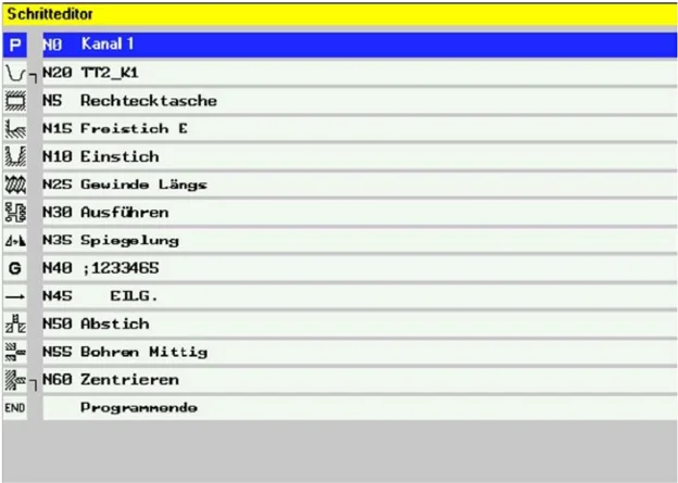
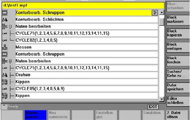
You can toggle between two views in step sequence display: The secondary level is either shown (+ Expanded) or hidden (– Collapsed).
You can toggle between both views using these buttons.
or
Example "Collapsed" view
Example "Expanded" view
6-264 © Siemens AG 2008 All rights reserved.


6 01/2008
6.4 Structured step sequence display (option)
"Program" operating area
References
For more information, please refer to:
- IAM / IM4, Chapter "Configuring settings using INI files" for the SEDITOR.INI file
- /PGA/ Programming Guide Advanced, Chapter "File and program management" for the SEFORM instruction
Select step sequence display
When requested via the softkey, the part program in the editor is displayed in steps.
To display a program selected in the editor in step sequence format, press the "Sequence" horizontal softkey in the expanded softkey bar. A new program only displays the empty step "End". The new program steps must be inserted before this step.

Additional information
- If a program contains a SEFORM instruction in the first 500 lines, step sequence display is automatically activated after opening.
- If you switch over to the dual editor, step sequence display is applied to both editor panes. When you switch back to the ASCII editor, both panes change to ASCII display.
- Combined step sequence and ASCII editor view is not supported.
- Options are required, if you wish to edit a program with SEFORM instructions in anything other than the ASCII editor.
Sequence of operations
Operation is virtually identical to that of the ASCII editor; the only different key functions for the step editor are:
- Steps such as G code and WAIT markers are opened with the ASCII editor.
- All standard cycles and contours can be recompiled.
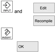
Press INSERT to insert a new step before the currently selected step. The editor window is automatically opened. The new step becomes visible in the step sequence display via the step name and - if configured - the associated icons.
Default text is free DIN code with G icons. New steps are added using cycle support.
Each new work step which is started on the same level with SEFORM, is the end of the preceding work step for this level.
Instead of the step name strings you can also write the text numbers which are used in the file with the configured (alarm) texts. Enter them in the format $8xxxx. They are then displayed in the currently active language.
6 "Program" operating area 01/2008 6
6.4 Structured step sequence display (option)
Mark block With collapsed display, the entire step is highlighted will all substeps and can be copied or deleted as required. With expanded display, the selected steps are highlighted.
Note
If you have switched between “Expanded” and “Collapsed” view while sequences were highlighted, the highlighting is removed for the sequences.
Copy block All selected steps are copied to the clipboard and can be inserted anywhere in the active channel or in another channel program (step or ASCII view). The clipboard is valid for each operating area at a time. An editor which is, e.g., activated by the simulation or as a correction editor cannot access the clipboard, which contains data created in the Program operating area.
Find/ Go to... Find If the search term is located in the step identifier, the cursor is positioned on the step. If the search term is not found within a step, a message is displayed "Search text not found". This is because only the displayed step identifiers are included in the search. The search works in the same way in the collapsed step sequence display and individual hits are only possible within the step identifier at zero level.
Go to: If the block number is located within a step, the cursor is positioned on the primary level or secondary level of the step.
6.5 Multi-channel step sequence programming (option)
Function
Application
Multi-channel step sequence programming is an extension of the single step sequence display to several channels.
Support is provided with the following tasks when working with multi-channel workpiece programs:
- Open by pressing the "Edit workpiece" softkey" once: All programs, which should be selected and executed in several channels simultaneously, are loaded into the editor.
- Display the step sequences of several programs: Left icon column per channel; right step display of the selected channel. You can switch between two display modes:
- Standardized and synchronized view during program generation before executing a trial run
- Time-proportional and synchronized view after executing a trial run on the basis of times recorded per step.
- Navigate in the channel's program (cursor up/down as well as previous/next step of same type) and from program to program of neighboring channels (cursor right/left)
- Edit the program in the standard ASCII environment (recompile or input softkey) or using the block functions at step level (change sequences in the program or distribute across programs).
- Optimize the sequence, processing time: Including the "Record times" program control, traverse programs.
The program sequence is monitored using "traces", which record the times for each step in the DAT file and form the basis for the time view. Based on this time-proportional view, programmers can quickly recognize which steps require a long time and carry out a redistribution or change in the sequence in relation to the channels.
Note
The preconditions for support when opening multi-channel workpiece programs can be configured by the machine manufacturer or machine setter: See "Create programming support for multi-channels".
6 "Program" operating area 6.5 Multi-channel step sequence programming (option) 01/2008 6
Preconditions and configuration
The "Edit workpiece" softkey enables you to edit a workpiece in the step editor.
The program directory offers the following files for channel assignment:
- Select a workpiece directory in which a DAT, JOB or MPF (with INIT/START) file with the same name is stored.
- Directly select a DAT file
- Directly select a JOB file using Select instructions
- Directly select a MPF file using INIT/START instructions.
It is also possible to create the channel assignment under a workpiece directory, e.g., for certain sequences on the machine stored in separate channel programs (setup, remove stock, measure...). In this case, you are recommended to store the most frequently used scenario in the file workpiecename.DAT, *.JOB or *.MPF. If you only want to open the setup scenario, select Setup.name.DAT, .JOB or .MPF in the data selector.
 To activate the step sequence display, press the "Edit workpiece" softkey and
- Select the workpiece in the workpiece directory WPD
- Select the JOB list
- <Workpiece name>.MPF is available (and no JOB list or DAT file with the same name).
If these preconditions are met, the DAT file is created or updated for:
- Section [Environment*] \rightarrow Multi-channel program display and editing
- Section [TimeData_] \rightarrow Recorded time for time-proportional step sequence display
- Basis for section-by-section simulation (see Chapter "Program simulation")
Settings. If step sequence display is active (single-channel and multi-channel) you can use the softkey to select whether, e.g., the times are to be specified in the step sequence displays next to the step identifiers. The settings become active immediately.
Templates
As with the JOB list, the internal file workpiece name.DAT for coordinating the multi-channel step sequence display and simulation can also be created from a template.
A workpiece name.DAT file is only created/entries entered in this file if the files were selected via workpiece name.WPD, workpiece name.JOB or workpiece name.MPF.
It is updated upon selection of a multi-channel program and the "Edit workpiece" softkey and when timing is active.

6 01/2008 "Program" operating area 6.5 Multi-channel step sequence programming (option) 6
See also: Chapter Commissioning operating area, HMI, "System settings".
Sequence of operations
Open With a single keystroke, all of the MPF available for a workpiece are opened in the assigned channel (Load/Unload/Select via job list), i.e., the corresponding programs no longer have to be selected individually in the data selector, but rather the workpiece softkey can be selected directly if all the necessary preparations have been made.
For existing part programs, which are shown in the step sequence display, the following preconditions must be met before opening: The channel assignment is defined in the following files:
- JOB list
- DAT file
- START/INIT in a start program
DAT environment The DAT file contains the description of which program should be opened and in which channel (channel number) of the machine (NC) this should be called up for execution; this is also referred to as the DAT environment.
Create a DAT file If this file does not already exist in the workpiece directory, it will be created automatically under the following preconditions:
- <Workpiece name>.job with the same name exists and this job list contains select instructions.
- Can be derived from the information required for the DAT environment.
- <Workpiece name>.mpf with the same name exists and this part program contains INIT/START instructions.
- Can be derived from the information required for the DAT environment.
As soon as a DAT file has been created and is available, a check is carried out each time it is opened to ensure that the DAT file has the latest time stamp. If the time stamp is not current, the file is updated.

6 "Program" operating area
6.5 Multi-channel step sequence programming (option)
6
Sequence of operations
Navigate
or
or
or
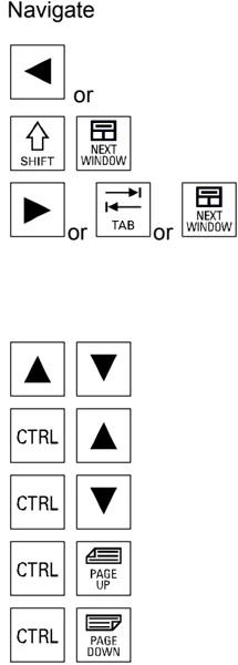
A step is searched for in the channel to the left of the current channel - which is executed at approximately the same time as the one just viewed. If the current channel is the leftmost channel, then the search is performed in the rightmost channel.
A step is searched for in the channel to the right of the current channel - which is executed at approximately the same time as the one just viewed. If the current channel is the rightmost channel, then the search is performed in the leftmost channel.
Return to previous/go to next step.
Back to previous step with the same execution (icon)
Go to next step with the same execution (icon)
Return to the previous synchronization mark
Go to the next synchronization mark
Further operation corresponds to the single step sequence display.
6.5.1 Multi-channel workpiece program views
Function
Window structure
The basic structure is the same for all display modes:
- Graphic section (left) with icons for the channel columns
- Step editor section (right) with icons, level symbols and step identifiers in ASCII
The size of both sections can be adjusted, so that there is always sufficient width for displaying and reading the step identifier, regardless of the number of channels.
6 01/2008 "Program" operating area 6
6.5 Multi-channel step sequence programming (option)
Views There are 3 display modes:
- Standardized view, all step sequences are the same length: Only if no current time data exist.
- Synchronized view: The synchronized view can be selected without a preceding timing operation. Press the "Find/ synchron. WAIT markers" softkey to change to the other view.
- Time-proportional view: Current time data are required for this view.
Number of channels Up to 10 channels can be opened and displayed side-by-side at any one time. The channels on a machine involved in a workpiece program can vary. This view is supported in that the associated step sequence icon column is only displayed for the programs of one channel. The width of the step sequence icons is defined dynamically.
Switch displays The following transitions between display types are available:
- When first opened:
- No time data available \rightarrow Standardized view
- Time data available \rightarrow time-related view
- In standardized view: only change to synchronized view possible.
- In time-related view: only change to synchronized view possible. No change is possible to the standardized view, as the steps and channels already have the correct relation to one another in the time-related view.
- In synchronized view: change to synchronized view possible, if
- No time data available \rightarrow Standardized view
- Time data available \rightarrow time-proportional view
Synchron. view
Switch to the standard ASCII editor You can change directly from the MCSP to the standard ASCII editor using the ASCII view softkey. The program which has the focus is then displayed as usual. You can return to the opened MCSP environment with or without changes using the Close editor or Cancel buttons.
6 "Program" operating area 01/2008
6.5 Multi-channel step sequence programming (option)
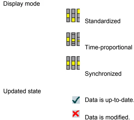
Display mode Standardized Time-proportional Synchronized
Updated state Data is up-to-date. Data is modified.
The timing operation must be repeated whenever changes are made to the program. The icon columns are marked with the associated channel numbers. The channel which has the focus (highlighted) is displayed at the top left with the channel name. The step identifiers on the right belong to the program which has the focus. The selected step is marked as identifier text and icon.
When changing between standardized and synchronized views the step sequence display is updated as on opening.
Standardized view
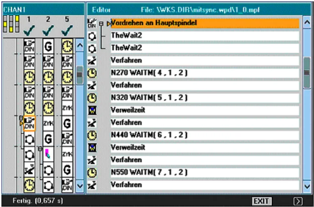
Properties Each step in the left window is displayed as a graphic (icon column per channel) in standardized pixel height, regardless of its content. Step identifiers are displayed for the program which has the focus; the program for channel 1 on the above screen.
6 01/2008 "Program" operating area 6
6.5 Multi-channel step sequence programming (option)
Time-proportional view
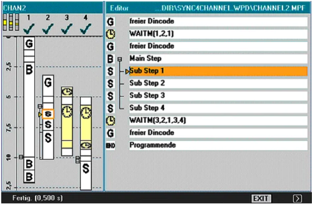
Properties Steps are displayed in the left window in proportion to the duration of their execution time. In the case of WAIT markers, the step length (i.e., the number of pixels in height is changed) is displayed in proportion to the waiting time.
Precondition for time-proportional view Timing by means of the execution of the workpiece program must have been performed. If timing has not been performed, the standardized view is displayed.
Programs which have been modified following timing are marked with "Data modified".
Computing the time again sets all programs to "Data updated".
Synchronized view
Synchron. view
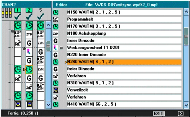
Properties The icons are displayed in a fixed size regardless of the time required for the step. The grouped synchronization steps are displayed in parallel with the channels (horizontal to one another) and filled with empty steps if the number of steps is uneven.
After switching to synchronized view, the data of all programs are
6 "Program" operating area 01/2008 6.5 Multi-channel step sequence programming (option) 6
initially "up-to-date". Making changes can lead to programs being marked with "Data modified".
When you change back to standardized view and back to synchronized view all programs are re-synchronized and displayed as "up-to-date".
Significance of icon background color
If you position the cursor on a synchronization icon additional states from a channel view are shown by means of the icon's background colors.
Green: Correct synchronization step -> The synchronization syntax/parameter assignment specified in the configuration file SEDITOR.INI is recognized. All addressed partners are found. Cursor on synchronization icon: The channel is affected by this synchronization and synchronization partner found.
Yellow: Not all partners can be checked: A channel number cannot be opened. At least one channel is addressed in the synchronization syntax that is not contained in workpiece.DAT. There may be an error in the program. Cursor on synchronization icon: The channel is affected by this synchronization, but at least one of the specified channel numbers is not registered in the workpiece.DAT file.
Red: Not all partners were found: An error is pending in the synchronization syntax. Consequently, the synchronization syntax must be checked and the faulty synchronization programming corrected in the addressed channel.
Unsymmetrical channel numbers in respect of synchronization partners found.
Examples are: Channel C1 WAITM(99,1,2,3) Channel C2 WAITM(99,1,2) Channel C3 WAITM(99,1,3)
Cursor on synchronization icon: In this channel, the partner was not found or the channel for the synchronization icon which has the focus contains at least one channel number from workpiece.DAT in which the partner being searched for was not found.
Programming must be modified either in the selected channel (too many or incorrect channel numbers specified) or in the searched channel (missing synchronization).
6-274 © Siemens AG 2008 All rights reserved.
6 01/2008 "Program" operating area 6
6.5 Multi-channel step sequence programming (option)
The channel is affected by this synchronization but the specified channel number does not match the selected synchronization icon.
Synchronization errors The difference in the number of channels is crucial for unsymmetrical channel numbers. The number of the channel in which the WAIT marker is programmed must not be included.
If the sequence is dependent on which channel reaches the WAIT marker first, an error is pending in the synchronization programming.
The first synchronization that was not found (red) is output in a dialog box:
Synchronization string, channel, channel to be synchronized: Further information on the cause of the fault can be obtained by positioning the cursor on the block number.
Pos. block number. Abort "Abort" softkey.
Notice Synchronous display of WAIT marks WIT marks can only be used once, otherwise errors can occur for the synchronous display.
Example: Channel1: Channel2: Channel3: WAITM(30,1,2) WAITM(30,2,1) --- WAITM(35,1,2 WAITM(35,2,1) --- WAITM(30,1,2,3) WAITM(30,2,1,3) (WAITM(30,3,2,1)
In this special constellation, there are no unique specifications as to how synchronization should be executed, i.e. the first WAITM of each channel has the same WAIT mark number 30, but they are completely independent of one another.
The result of the synchronization depends on the channel which you used to start synchronization: If you start with either Channel 1 or 2, synchronization runs without any problems and the expected result is supplied. However, if you start with a channel number, then an error is definitely output.
6 "Program" operating area 01/2008 6
6.5 Multi-channel step sequence programming (option)
6.5.2 Activating timing
Function
Timing for steps is based on the monitoring of times per step and per channel in relation to the program end or reset states of all involved programs (end of step per channel and creation of TimeData_* entries in the relevant file).
Timing Preparation phase - Message:
- Timing initializing. Please wait ........ Initiation of execution – Message: Timing is active. After completion - Message:
- Recorded data is processed. Please wait ........
Timing is activated in the Machine operating area under "Program control". The steps are initialized for all channels stored in the relevant DAT environment.
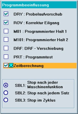
Edit workpiece The multi-channel program display is opened when you press the "Edit workpiece" softkey once the above listed preparations have been completed.
6
"Program" operating area
6.5 Multi-channel step sequence programming (option)
6
Evaluation and optimization Reposition the steps or synchronization points (WAITM()) so that multi-channel execution improves parallelism and therefore shorter workpiece processing times:
- Select extremely long steps and analyze the environment
- Redistribute some tasks across the channels (e.g., break down longer-lasting steps so that processing can be carried out by several channels in parallel)
- Optimize synchronization between the channels
- Change the technological process (e.g., use steel profiles or special tools with a shorter processing time)
Additional information
After making changes to the program, you need to process the workpiece again to compute the new times. Programs which have been modified are marked with a red X until the times have been updated.
If timing has not been performed, all steps in the program are displayed with equal time lengths. The computed times are saved in a .DAT file for each workpiece.
6.5.3 Activating simulation
Function
The multi-channel step sequence display also supports multi-channel simulations. Here, the NC language labels such as WAIT2: WAITM are inserted in the NC part program. The labels are removed again when you exit the simulation and return to multi-channel step sequence display.
The labels continue to remain in place, if you are in the simulation or in the correction editor and also:
- The control is switched off.
- The write access for the opened file is canceled.
Multi-channel, section by section program simulation
There are specific NC instructions for program coordination for synchronizing program execution as required for multi-channel manufacturing of workpieces: (INIT(..), START(..), WAITM(..) etc.). In principle, they can be used to start independent program sections in parallel channels almost simultaneously and synchronize them via e.g.
6 "Program" operating area 01/2008 6
6.5 Multi-channel step sequence programming (option)
WAITM(Marker No., ...) once the associated machining operations have been executed and before starting the next sections.
Simultaneous aspects can only be sequentially emulated with simulation. NC program labels serve to mark program sections. Emulating the multi-channel program coordination in the simulation assumes that NC instructions for program coordination were marked with NC labels (manually or automatically during program generation). Simultaneous operational sequences which are independent of one another are executed one after the other in the respective channels (channel change per section required), before sequences are created for the next sections in the same manner. The result in the simulation is a similar sequence of machining steps to that on the machine.
Limitations
- Only one out of 10 possible channel instances can be assigned to the single-channel graphic module (simulation display) at any one time (no simultaneous mode for channels!). Commands for multi-channel program coordination (INIT(..), START(..), WAITM(..) etc.) are not executed in the program interpreter for the simulation.
- Partial processing of the "channels" on the same stationary blank are superimposed.
- Path labels are universal markings/section structure aids in NC programs which can trigger specific actions during the simulation run:
- Path labels can be optionally displayed in the graphic
- The intermediate time can be computed for sections delimited by path labels.
- The graphic state can be stored temporarily for sections that are delimited by path labels.
Path labels have a defined label syntax: Identifiers for simulation should exist singly in one NC block in so far as possible.
- The channel changes section by section with defined path labels (NC program labels).
Section limitation using path labels
If the "Stop label" column is clearly defined, the "Start label" is created implicitly:
- An empty "Start label" field has the same meaning as a start from the beginning of the program
- An empty "Stop label" field has the same meaning as a stop at the end of the program
- With the same "program name", the "start label" of a section is equal to the "stop label" of the preceding section
- If start and stop labels are not specified, the entire program is executed.
6-278 © Siemens AG 2008 All rights reserved.
6
6.5 Multi-channel step sequence programming (option)
"Program" operating area
\begin{tabular}{p{0.22\textwidth} p{0.75\textwidth}} \textbf{JOB list} & If a job list or a corresponding list of the step editor (MCSP) exists in the current workpiece directory, when simulation is selected, then the machining list , is automatically pre-assigned - if this still does not exist. \ & After confirmation of the machining list with OK, the relevant [JOB] section is generated in the workpiece-specific DPWP.ini file. \ & The following entries are managed: \ & \quad \bullet Program name.type \ & \quad \bullet Channel number \ & \quad \bullet Spindle unit: Main spindle, counterspindle, variable \ & \quad \bullet Start label (path label) \ & \quad \bullet Stop label (path label) \ & \quad \bullet Length of the machining list (number of sections) \ & The machining list can be updated at any time via the "Channel/spindle" menu. \ \textbf{Simulation sequence} & The simulation sequence is controlled by the contents of the machining list menu "Channel/spindle" and supports simulation of multi-channel program coordination: \ & \quad \bullet Selecting the list validates the specified operational sequence. \ & \quad \bullet In each sequence step the designated program can be fully executed - as before - (i.e. from program start to M2/M30 or M17) in the specified channel by leaving the fields "Start label" and "Stop label" empty \ & \quad \bullet With each sequence step you can change to a different channel at the section of another program (section by section channel change) up to the specified "Stop label". \ & \quad \bullet If a label which was not previously defined as a "Stop label" for the sequence is specified in the "Start label" field, an implicit search run will be performed (without output of graphics) up to the "Start label" in the selected program before the simulation run is started. \ & \quad \bullet If the label assignments are inconsistent, the simulation is reset to the last valid state and a message is issued to this effect, e.g. "Label xxxxxx not found. Adapt label definition in machining list or adapt part program!". \ & \quad \bullet Each sequence step should be started separately and can also be reset separately. \ & \quad \bullet Section-by-section change of the spindle unit within the step sequence is permissible and controlled by means of keywords from the program. \ \end{tabular}
6 "Program" operating area 01/2008 6
6.5 Multi-channel step sequence programming (option)
- The section-by-section channel change during program run is only supported in conjunction with specification of the corresponding program labels (path labels), which are either programmed manually or generated internally via integrated functions.
Simulation result By superimposing the partial executions from the machining list on a blank the section by section simulation mode only changes for the sequence of machining sections in the graphic. There is no change in the overall result.
Search run The list of machining steps (for which an intermediate model is available in the graphic module in the current simulation state) allows direct selection of a section in the simulation. See also "Display and colors"/Manage path labels. The corresponding section is selected and confirmed with OK. The simulation will start at the beginning of this section and is based on the state which the preceding section was in the last time its execution was completed.
Timing The timing table shows an analysis of the timings calculated from within the simulation and encompasses the specified sequence of execution up to the current state of the simulated machining sections. The timing table is in cumulated form and takes into account the defined downtime values (for T, S, M and H functions if present); data is shown for the respective section limits.
Timing The section limits are marked with the associated ASCII label derived from the "Stop label" (if present) or with M30 at the end of the program. Times are computed at each section end.
6.6 Multiple editor (option)
Starting point → graphic step view After the softkey “Edit workpiece” is pressed, then the graphic step view is displayed:
- At the left with the so-called icon bars of all of the channel programs loaded in tthe MCSP
- At the right, with the so-called working step view of the channel in focus
HSK1/9 ASCII view → multiple ASCII editor Using the HSK1(&=HSK9)"ASCII-|View" (toggles with "working steps") from the MCSP step view, with a keystroke, then the program actually in focus is not as before displayed in a single ASCII full view, but instead is changed with the adjacent channels in a multiple ASCII full view that displays the 1-4 channel programs from the programs loaded in the MCSP next to one another in ASCII and offers all of the known editor functions.
6.6.1 Operator/display functions in the ASCII full views

Function
Overview In addition to the known ASCII editor functions, the operator is offered the following functions:
- With the change into this multiple ASCII full view, the HSK1(&=HSK9) toggles at the "working steps" so that it is possible to directly toggle between the MCSP step view and the ASCII full view.
- Using the hardkey focus change, it is possible to change from left to right to the adjacent windows/channel programs.
- Using the HSK7 "Editor large" (or HSK15 depending on what the machinery construction OEM has configured, then a change is made into the so-called single ASCII full view with the display of the channel program presently in focus. In this case, one of the ASCII editors is placed over the complete width of the other editors. HSK7/15 toggles with "editor small" so that it is possible to return to the multiple ASCII full view with a keystroke.
- Using the HSK16 "channel selection" a channel selection dialog box is displayed both in the MCSP step view as well as also in the multiple ASCII full view.
- The graphic step display with the so-called icon bars is also displayed for orientation purposes; this means that the focus frame with arrow gives the operator the information as to which step his ASCII line belongs as long as nothing has been changed as a result of changes in the part program in the ASCII view after the last HSK1(&=HSK9) selection. This can be identified by the "checkmark icon" above the icon bar. As soon as a "cross icon" is shown here, then the step sequence has still not been updated
6 "Program" operating area 6.6 Multiple editor (option) 01/2008 6
and especially steps that follow after the changed program locations are no longer up-to-date. The update of the steps can be forced by changing the view into the step view HSK1 working steps + renewed HSK1 ASCII view (parser run).
In addition, when using the mouse, it is possible to directly select a step – as long as it involves steps from channels that are currently selected or are displayed:
- The graphic step display with the so-called icon bars can be switched-in or switch-on using the channel selection dialog box subsequently described.
HSK7/15 Editor|Large → single ASCII editor Single ASCII full view after pressing HSK "Editor Large"
HSK16 channel selection dialog box in the step view The following dialog box is displayed if HSK16 is pressed in the step view:
Using this dialog box, the user sets the behavior of the MCSP for the transition from the environment work steps into the multiple ASCII view.
The user can either select an automatic ("automatically determined using synchronization") and a manual ("manual entry") channel selection.
Pre-assignment (default setting) of the dialog box When this dialog box is displayed, it is pre-assigned (default settings) the subsequent entries from the section [MultiASCIIView] of the SEDITOR.INI.
- "SyncAlgo" key This specifies the channel selection type. 0 – manual entry 1 – automatically determined through synchronization (default)
- "ChannelPreselection" key Specifies the channels for the "manual entry". e.g. ChannelPreselection = 1,3 without default
- "MaxChannels" key Specifies the number of channels to be displayed for the automatic determination.
- "SearchDirection" key This specifies the direction of the search after the synchronization step. 0 – upwards (default) 1 – downwards
- "WithStepView" key Specifies the display of the graphic step view ("icon bar"). 0 – no graphic step view 1 – with graphic step view (default)
6 01/2008 "Program" operating area 6.6 Multiple editor (option) 6
Additional keys that are not listed in the dialog box, but decisive for setting the ASCII full view:
In SEDITOR.INI also in section [MultiASCIIView]
- "ZoomFont" key Specifies whether the font of the editors should be zoomed in the m-ASCII view - or not. 0 – VGA font, the font is not zoomed (default) 1 – the font is zoomed
In MCSE.INI in section [General]
- "SwitchHSK7_15" key This specifies whether in MCSP the HSK7 is assigned with "Simulation" or with "Editor large|small" in exchange with HSK15. 0 – no exchange (default) 1 – exchange HSK7 with HSK15 contents
Automatic determination through synchronization
For the automatic channel selection, starting from the step currently in focus in the step view, the next synchronization step is determined. Of course, initially it is checked as to whether the step current in focus is a synchronization step. If it is not a synchronization step, then depending on the selected search direction, a search is either made upwards or downwards.
If a synchronization step was able to be found, then from this associated synchronizing channels/MPFs are determined.
Example:
A WAITM(99,2,3,5,7) in channel 3 supply the synchronizing channels 2, 5 and 7. To start, the found synchronizing channels/MPFs are filtered as to whether the files are also currently opened in the MCSE. Channels/MPFs that are not in the synchronization command are ignored. For instance, referred to WAITM(99,2,3,5,7): Existing channels: 2, 3, 5 → synchronizing channel 7 is ignored.
A check is then made as to whether the number of channels to be displayed was complied with.
The following rules apply:
- The number of channels to be displayed (refer to the entry "number of channels") must lie between 1 and 4.
- If a larger number is obtained from the number of filtered synchronizing channels, then starting from the channel currently in focus, a search is made to the left (sequence of the channels as in the graphic step view) for channels to be displayed - and if required, the search is continued from the far right to the left: → REMOVE
- If a smaller number is obtained from the number of filtered synchronizing channels, then starting from the channel currently in focus (sequence of the channels as in the graphic step view), a search is made for channels that are still not to be displayed - and if required, the search is continued from the far left to the right: → Fill-up
6 "Program" operating area 01/2008 6
6.6 Multiple editor (option)
- If a synchronization step was not found, then starting from the channel currently in focus to the right of this, it is filled up, or if required, the search is continued from the far left to the right until the maximum number of channels to be displayed is reached. →Fill-up
Manual entry
For the manual channel selection, the user is shown all of the MPFs currently opened in the MCSP in a tabular form. Using the checkboxes, the user has the possibility of selecting the channel programs he requires for display in the multiple ASCII view.
The following rules apply:
- The number of channels/MPFs selected for display must lie between 1 and 4. If the number lies outside this valid value range, then an appropriate message is displayed with the “OK” or “Save” softkeys.
- Graphic step view: This menu point can be used to determine whether the graphic step view – displayed at the left – (“icon bar”) should be visible in the multiple ASCII view – or not. In order to obtain more space for the ASCII editors, it suddenly makes sense to hide the graphic step view. The graphic step view takes up more screen width depending on the number of channels in the MCSP: for 10 channels, up to max. 60%.
Softkeys
The “OK” softkey is used to accept the current settings – under the assumption that the setting check was positive. The display in the m ASCII view is then completely built-up again.
The “”Abort” softkey, the channel selection dialog box is executed without any further action.
The “Save” softkey is used to accept the current settings in the SEDITOR.INI; these settings then become effective.
6 01/2008 "Program" operating area 6.6 Multiple editor (option) 6
6.6.2 Alignment of the channels/MPFs to be displayed
Function
The channels/MPFs are aligned with respect to one another when changing-over from the step view into the multiple ASCII view.
- Starting from the step current in focus, the steps are used that are at the same height horizontally in the graphic step view.
- Alignment in ASCII next to one another on a common reference line in the upper lines of the ASCII window.
Note
For the time-based view for cursor left/right, the end of step in time is used as reference to select the step in the adjacent channel. However, it is not the last ASCII line of the step so obtained – but for the alignment of the channels next to one another, in the reference line, it is the first line that is relevant - the start of the step.
HSK16 channel selection dialog box in the multiple ASCII view
The following dialog box is displayed if HSK16 is pressed in the multiple ASCII view:
When the channel selection dialog box is displayed, the currently displayed channels/MPFs all of the channels/MPFs open in the MCSP are marked (selected) by activating the associated checkboxes in the list.
In this dialog box, the user can manually influence the channels selected by changing over into the multiple ASCII view. The possible settings correspond to those described in the section “Manual entry”.
Pre-assignment (default setting) of the dialog box
The dialog boxes pre-assigned from the actual environment, this means::
- When “automatic determination through synchronization” is active, channels are selected sensitive to the context depending on the cursor when selecting the multiple ASCII view. When the dialog box is opened, these channels are selected in the checkbox.
- When channel selection “manual entry” is active, the last selected or those saved in the ini are selected – if no other selection was made.
6 "Program" operating area 01/2008 6
6.6 Multiple editor (option)
Softkeys
The “OK” softkey is used to accept the current settings – under the assumption that the setting check was positive. The display in the m ASCII view is then completely built-up again.
The “Abort” softkey, the channel selection dialog box is executed without any further action.
HSK16 channel selection dialog box in the single ASCII view
If HSK16 is pressed in the single ASCII view, the same dialog box is obtained – with the following difference: The cursor is located on the selection icon bar yes/no and returns to the single ASCII editor as long as nothing was changed regarding the channel pre-selection; otherwise, it returns to the multiple ASCII editor. The cursor in the opened dialog box is located on the graphic step view.
Re-numbering HSK11
The function is only effective for the channel currently in focus. This is the reason that it remains in the ETC bar.
HSK13 settings
The settings made become effective for all opened dialog boxes (not only those that are displayed). This is the reason that a return jump is made to the main bar.
6.7 Free contour programming
Function
Free contour programming is a support tool for the editor. The contour programming function enables you to create simple and complex contours.
An integrated contour calculator (geometry processor) calculates any missing parameters for you, provided that they can be calculated from other parameters. You can link together contour elements. Contour transition elements "radius" and "chamfer" are also provided.
The programmed contours are transferred to the edited part program.
Technologies
The scope of functions of the contour calculator differs depending on the chosen technology:
Functions which are only available in the turning technology include:
- Toggling between radius/diameter programming (DIAMON, DIAMOF, DIAM90)
- Chamfer/radius at the start and end of the contour
- Undercuts as transition elements between two axially parallel straight lines, where one runs horizontally and the other vertically (Form E, Form F, thread undercut, free undercut)
Functions which are only available in the milling technology include:
- Contours with symmetry (mirroring)
- Contours with repetitions
- Combinations of both
The contour calculator takes into account channel-specific display machine data. As it does not know which channel the program is being created for, it always analyzes the display machine data of the 1st channel.
Allowances parallel to the contour, which are required for grinding, can be created by free contour programming and modified again if necessary.
6 "Program" operating area
6.7 Free contour programming
Contour elements
The following are contour elements:
- Starting point
- Straight line (planar, longitudinal, inclined)
- Circular arc
A pole is a pseudo contour element. Straight lines and circular arcs can also be defined by polar coordinates in reference to a pole.
Additional information
- The valid geometry axes in the first channel are determined and used in the part program.
- The contour editor uses the last programmed axis position for the starting point, without allowing for previously valid G functions.
- You must also specify the side on which the contour allowance should lie, e.g., "right" or "left".
6.7.1 Programming a contour
Sequence of operations
New contour
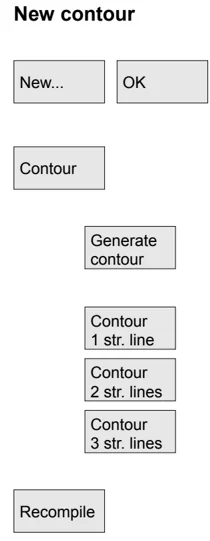
Use the "Workpiece" and "Part program" softkeys in the Program operating area to select an existing program and press the "Input" key or open a new part program using the "New" softkey, enter a name and confirm with "OK". You are now in the ASCII editor.
The "Contour" softkey displays a vertical softkey bar with the following options:
The contour calculator is activated to generate a contour chain from contour elements.
Preparatory cycles are displayed with help displays for creating straight lines and transition elements, if applicable.
You can edit an existing contour by selecting the "Recompile" softkey. The editor cursor must be positioned inside the contour to do this.
©Siemens AG 2008 All rights reserved.