9 Commissioning operating area
9.1 Startup main screen
9.1 Startup main screen
Danger
Changes in the Commissioning operating area have a significant influence on the machine. Incorrect configuration of the parameters can endanger human life and cause damage to the machine.
Access to certain menus in the "Commissioning" operating area can be protected by keylock switch or password.
This Chapter describes functions which the machine operator can perform on the basis of his or her access rights.
References
Further information regarding startup (commissioning) is provided in Commissioning Manual, HMI-Advanced (IM4).
Target groups include:
- System personnel
- Machine manufacturer
- Service personnel
- Machine users (machine setters)
Function
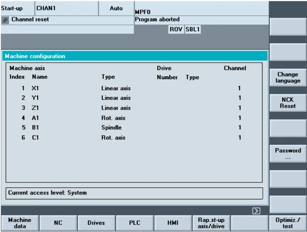
The "Machine configuration" window is displayed in the "Commissioning" main screen.
The diagram shows the status of the SINUMERIK solutionline:

9 01/2008 Commissioning operating area 9.1 Startup main screen 9
Horizontal softkeys
\begin{tabular}{ll} Machine & Enables you to edit the machine data for all areas. \ data & (see Section 9.2) \ NC & You can perform an NC boot in different modes (see Section 9.3). \ Drives & Select this softkey to configure the parameters for one or more drives. \ & You can page through the drives using the "Drive +" and "Drive –" \ & vertical softkeys. The "Drive selection..." vertical softkey opens a \ & dialog allowing you to select a drive. By using these three vertical \ & softkeys you can select all of the drive devices on all PROFIBUS \ & segments. The "Change..." softkey starts the configuration assistant \ & for the drive. \ References & /IDsl/ Commissioning Manual CNC Part 1 (NCK, PLC, Drive) \ & /IAD/ Commissioning Manual SIMODRIVE 611 digital \ PLC & The PLC status function is available. \ & You can update the date and time of the PLC and HMI \ & (see Chapter 9.4). \ HMI & Here you can enter the settings on the user interface (see Section \ & 9.5). \ Axis/drive- & This menu contains functions for commissioning the axes and drives. \ quick c & \ References & /FBA/ Description of Functions, Drive Functions \ Optimiz. / & The system provides support here for commissioning the drive. \ test & Coupled axes are supported for measuring in the current control loop, \ & speed control loop or position control loop. \ $>$ & Expanded softkey bar: \ Licenses & The license function is only available on the SINUMERIK solution line. \ & Here you can manage and activate licenses for installed software and \ & options (see Section 9.7). \ Tool & This is where you can enter tool data, create tool lists and assign the \ managem. & tool magazine locations. \ References & /FBA/ Description of Functions, Tool Management \ \end{tabular}
SINUMERIK 840Di sl/840D sl/840D Operating Manual HMI-Advanced (BAD) - 01/2008 Edition \hfill 9-431
9 Commissioning operating area
9.2 Machine data
9.2 Machine data
Danger Changes in the machine data have a considerable influence on the machine. Incorrect configuration of the parameters can endanger human life and cause damage to the machine.
Access to the machine data operating area can be controlled by keylock switch or password.
Function
Areas The machine data is divided into the following areas:
- General machine data ($MN)
- Channel-specific machine data ($MC)
- Axis-specific machine data ($MA)
- Display machine data ($MM)
- Drive-specific machine data ($M_)
- Machine data control unit: Drive parameters (solution line)
- Machine data feed-in: Drive parameters (solution line)
A separate list display is provided for each of these areas in which you can view and edit machine data.
The following information about the machine data is displayed from left to right:
- Machine data number
- Machine data name, with field index if applicable.
- Value of the machine data
- Unit of the machine data
- Effectiveness
If the machine data does not use units, no units are displayed. If the data is not available, the "#" symbol is displayed instead of the value. If the value ends in an "H", it is a hexadecimal value.

9.2 Machine data
The physical units of machine data are displayed on the right-hand side of the input field.
Examples
| Unit | Description |
|---|---|
| m/s**2 | m/s² (meter/second squared): Acceleration |
| rev/s**3 | rev/s³ (revolution/second to the power of 3): Change in rate of acceleration for rotating axis |
| kg/m**2 | kgm² (kilogram/meters squared): Moment of inertia: |
| mH | mH (millihenry): Inductance |
| Nm | Nm (Newton meters): Torque |
| us | µs (microseconds): Time |
| µA | µA (microamperes): Electric current |
| µVs | µVs (microvolt-seconds): Magnetic flux |
| userdef | User-defined: The units are defined by the user. |
The right-hand column indicates when a machine data becomes effective:
- so = immediately effective
- cf = when confirmed via the "Activate MD" softkey
- re = reset
- po = POWER ON (NCK Power On reset)
Function
File functions
Enter the name of the file in which you wish to save the operands. You can select an existing back-up file from a list.
File functions: see Subsection 8.5.4
9.3 NC
Function

Commiss. switch The commissioning switch function is only available on the SINUMERIK powerline. You can only define the commissioning switch settings if you have the appropriate access rights to do so.
NCK addresses The NCK address function is only available on the SINUMERIK powerline. View the NCU address and change it. It is normally only necessary to edit the address for M: N operation. You cannot undo an address change with general reset. It is not saved in a series commissioning archive.
NC memory The NC user memories available for programs and data are displayed here:
- Memory overview
- SRAM assignment in bytes
- DRAM assignment in bytes
Further information on the selection can be displayed using the "Details" softkey.
V ertical softkeys
NCK reset The NCK reset and NCK general reset functions are only available in the SINUMERIK solutionline:
- "NCK Reset" performs a warm restart of the NC.
- "NCK general reset" resets all of the machine data to the default values.
NCK gen. reset
9.4 PLC
Function
Changes can only be made with the corresponding access authorization (password):
- Setting date/time (see blow)
- PLC status for PLC operands (see Section 8.5)
- File functions (see Subsection 8.5.4)
Danger
Changes in the states of PLC memory locations have a major impact on the machine. Incorrect configuration of the parameters can endanger human life and cause damage to the machine.
Function
You can change the date and time of the PLC and manually synchronize the date and time of the PLC and HMI.
Sequence of operations
The "Commissioning" operating area is selected.
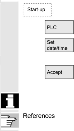
Press the "PLC" softkey.
The horizontal and vertical softkey bars change.
Press the "Set date/clock" softkey. The "Set date/clock" window is displayed.
Enter the correct values in the input fields.
The date and time on the HMI are transferred to the PLC.
The synchronization can be verified in the "Current time:" output field.
The set values are retained when the control is rebooted.

References
Commissioning Manual HMI-Advanced (IM4)
9.5 Optimization/test (SINUMERIK powerline)
Function
This menu contains functions for commissioning the axes:
- Current control loop
- Speed control loop
- Position control loop
- Function generator
- Circularity test
- Servo trace
- AM/MSD self-optimization (inactive)
- DAC configuration (inactive)
Expanded softkey bar:
- Aut. selector setting
Servo trace involves the recording of up to 10 bit signals throughout the measuring time for bit-encoded Safety Integrated signals.
References
/FBA/ Function Manual Drive Functions
/FBSI/ Function Manual Safety Integrated
Measurement of coupled axes
For commissioning SIMODRIVE 611 digital drives, coupled axes are supported for measuring in the current control loop, speed control loop or position control loop:
- Pure gantry axis groupings
- Pure master/slave relationships
- Hybrid coupling of master/slave axes with gantry axes
You can enter specific measuring parameters and select a measurement for each available axis in these axis groupings. The following measuring parameters are available:
- Amplitude leading axis or master axis
- Amplitude synchronized axis/axes or slave axis/axes
- Bandwidth of the frequency range to be analyzed
- Information on measuring accuracy and measurement duration increase
- Delay settling time
- OFFSET to accelerate via an acceleration ramp

/IAD/ Commissioning Manual:
Section "Measuring functions for coupled axes"
9.5 Optimization/test (SINUMERIK powerline)
Display all coupled axes
You can record the results for up to two axes simultaneously. There is always only one leading axis. All other axes are synchronized axes; their amplitude can be assigned separately. All active axes of the grouping are displayed.
For non-mixed couplings, the following axes can be seen as a maximum: for gantry axis grouping, for master/slave couplings
- one leading axis and two synchronized axes.
- one master axis and two slave axes
With a hybrid master-slave coupling with pure gantry axes the leading axis always comes from the pure gantry axis grouping. All other axes are synchronized axes. The texts displayed in the operator interface change and are updated according to the active type of coupling.
You can navigate through all active axes in the "Gantry measurement" or "Master / slave measurement" selection screens where all active couplings are displayed. You can measure up to 2 axes simultaneously. The measuring process must be repeated after each axis selection.
The axis couplings show the axis identifiers e.g. X1, Z1 or A1 as well as the axis number of the respective axis grouping. The values have the following meanings: SRM Synchronous motors (synchronous rotation motor) ARM Asynchronous motors (asynchronous rotation motor)
Additional information
The HMI does not support initiation of a measurement job for a master/slave coupling in the position control loop. If you are currently performing a position control measurement on an axis which is coupled but not initiated by the HMI, the start is inhibited for this slave axis and a message is displayed.
When optimizing or measuring gantry axes, HMI Advanced V06.03.xx should be used if at the complete coupling at least two involved axes are configured on one control module. This also includes master/slave axes.
9 Commissioning operating area 9.5 Optimization/test (SINUMERIK powerline) 9
Notes
10
01/2008 Maintenance 10
Maintenance
- 10.1 Operating data ........ 10-440
- 10.2 Cleaning ........ 10-441
10.1 Operating data
Operating data
| Value | |
|---|---|
| Air humidity, humidity class to DIN 40040 | F |
| Atmospheric pressure | 860 to 1080 hPa |
| Protection against physical contact protection class to DIN VDE 0160 | I |
| Degree of protection according to DIN 40050 | |
| • Front of operator panel | IP 54 |
| • Back of operator panel | IP 00 |
| • Front of machine control panel | IP 54 |
| • Back of machine control panel | IP 00 |
References
You will find the comprehensive operating data in the documentation /BH/ Operator Components Manual and in the relevant information sheets.

10.2 Cleaning
Cleaning agents
The front of the monitor and the surface of the operator panel front can be cleaned. For dirt that is relatively easy to remove, standard household washing-up liquid, or an industrial cleaner (such as "Special Swipe") can be used. These cleaners will also remove dirt containing graphite.
Cleansing agents which contain one or more of the following ingredients can be used for a short period of time:
- Diluted mineral acids
- Bases
- Organic hydrocarbons
- Detergent solutions
Plastic material used
The plastic material used on the front of the OP015, OP012 or OP015 is suitable for use on machine tools.
It is resistant to:
- Greases, oils, mineral oils
- Bases and lyes
- Detergent solutions and
- Alcohol
Solvents such as chlorinate hydrocarbons, benzene, esters and ethers should be avoided!
10 Maintenance 01/2008 10 10.2 Cleaning
Notes
10-442 © Siemens AG 2008 All rights reserved.

A 01/2008 Appendix A
Appendix
- A Abbreviations ........ A-444
- B Terms ........ A-448
A-443
A Abbreviations
| Abbreviation | Definition |
|---|---|
| O | Output |
| ASCII | American Standard Code for Information Interchange American Standard Code for Information Interchange |
| Mode group | Mode group |
| OPI | Operator Panel Interface |
| CAD | Computer-Aided Design |
| CNC | Computerized Numerical Control Computerized Numerical Control |
| CR | Carriage Return |
| DAU | Digital-to-Analog Converter |
| DB | Data Block in the PLC |
| DBB | Data Block Byte in the PLC |
| DBW | Data Block Word in the PLC |
| DBX | Data block bit in the PLC |
| DIN | Deutsche Industrie Norm (German Industry Standard) |
| DIR | DIRectory: Directory |
| DPM | Dual-Port Memory |
| DOS | Disk Operating System |
| DRAM | Dynamic Random Access Memory |
| DRF | Differential Resolver Function: Differential revolver function (handwheel) |
| DRY | DRY run: Dry run feedrate |
| DW | Data Word |
| I | Input |
A-444

A 01/2008
A Abbreviations
\begin{tabular}{ll} FRAME & Data block (FRAME) \ BP & Basic program \ GUD & Global User Data : Global user data \ HD & Hard Disk Hard disk \ AuxF & Auxiliary Function \ MSD & Main Spindle Drive \ HW & Hardware \ IBN & Commissioning \ ICA & Interpolatory Compensation Interpolatory compensation \ INC & Increment : Increment \ INI & Initializing Data : Initializing data \ IPO & Interpolator \ ISO & International Standard Organization \ ISO code & Special punched tape code, \ & Number of holes per character always even \ JOG & JOGging: Setup mode \ C1 .. C4 & Channel 1 to channel 4 \ LED & Light Emitting Diode: Light emitting diode \ LF & Line Feed \ K$_v$ & Servo gain factor \ LUD & Local User Data \ MB & Megabyte \ MBDDE & \ MD & Machine Data \ \end{tabular}
A-445

A Appendix
A Abbreviations
\begin{tabular}{ll} \textbf{MDA} & Manual Data Automatic: Manual input \ \textbf{MCS} & Machine Coordinate System \ \textbf{MLFB} & Machine-readable product designation \ \textbf{MMC} & Man-Machine Communication: User interface on numerical control systems for operator control, programming and simulation \ \textbf{MPF} & Main Program File: NC part program (main program) \ \textbf{MPI} & Multi-Point Interface Multiport Interface \ \textbf{MCP} & Machine Control Panel \ \textbf{NC} & Numerical Control: Numerical control \ \textbf{NCK} & Numerical Control Kernel: NC kernel with block preparation, traversing range, etc. \ \textbf{NCU} & Numerical Control Unit: NCK hardware unit \ \textbf{ZO/WO} & Zero/work offset \ \textbf{OEM} & Original Equipment Manufacturer \ \textbf{OP} & Operator Panel: Operating equipment \ \textbf{PCU} & Programmable Control Unit \ \textbf{PCMCIA} & Personal Computer Memory Card International Association: Plug-in memory normalization board \ \textbf{PG} & Programming device \ \textbf{PLC} & Programmable Logic Control: Adaptation control \ \textbf{REF} & REFerence point approach function \ \textbf{REPOS} & REPOSition function \ \textbf{ROV} & Rapid Override : Input correction \ \textbf{RPA} & R-Parameter Active: Memory area in NCK for R-NCK for R parameter numbers \ \end{tabular}
A-446

A Abbreviations
| Abbreviation | Definition |
|---|---|
| SBL | Single Block : Single block |
| SD | Setting Data |
| SEA | Setting Data Active: Identifier (file type) for setting data |
| SK | Softkey |
| SKP | SKiP: Skip block |
| SPF | Sub Program File : Subprogram |
| SRAM | Static RAM (non-volatile) |
| SW | Software |
| SYF | SYstem Files System files |
| TEA | Testing Data Active: Identifier for machine data |
| TO | Tool Offset Tool offset |
| TOA | Tool Offset Active: Identifier (file type) for tool offsets |
| UFR | User Frame: Zero/work offset |
| FDD | Feed Drive |
| WCS | Workpiece coordinate system |
| TO | Tool offset |
| TC | Tool change |
| ZOA | Zero Offset Active: Identifier (file type) for work offset data |
A-447

A Appendix B Terms 01/2008 A
B Terms
Important terms are listed in alphabetical order. For terms, that appear in the explanation and for which there is a dedicated entry, reference is made using →.
A
Axes In accordance with their functional scope, the CNC axes are subdivided into:
- Axes: Interpolating path axes
- Auxiliary axes: Non-interpolating feed and positioning axes with an axis-specific feed rate. Auxiliary axes are not involved in the actual machining, and include for example tool feeders and tool magazines.
Axis identifier Axes are labeled in accordance with DIN 66217 (for a clockwise orthogonal \rightarrow coordinate system) with the letters X,Y, Z. \rightarrow Rotary axes which rotate about X,Y,Z are labeled with the letters A, B, C. Additional axes parallel to the above can be identified with further address letters.
Axis address See \rightarrow Axis identifier
Axis name See \rightarrow Axis identifier
Address An address is the identifier for a certain operand or operand range, e.g., input, output, etc.
Alarms All \rightarrow messages and alarms are displayed on the operator panel in plain text with date and time as well as the appropriate symbol for the delete criterion. Alarms and messages are displayed separately.
- Alarms and messages in the part program Alarms and messages can be displayed directly from the part program in plain text.
- Alarms and messages from PLC Alarms and messages relating to the machine can be displayed directly from the PLC program in plain text. No additional function block packages are required for this purpose.
Drive * *
User-defined variable Users can define variables in the \rightarrow part program or data block (global user data) for their own use. A definition contains a data type specification and the variable name. See also \rightarrow System variable.
A-448
A 01/2008 B Appendix Terms A
User program User programs for the S7-300 automation systems are created using the programming language STEP 7. The user program has a modular layout and consists of individual blocks. The basic block types are: Code blocks: These blocks contain the STEP 7 commands. Data blocks: These blocks contain the constants and variables for the STEP 7 program.
User memory All programs and data, such as part programs, subprograms, comments, tool offsets, and zero offsets/frames, as well as channel and program user data, can be stored in the shared CNC user memory.
Working area limitation With the aid of the working area limitation, the traversing range of the axes can be further restricted in addition to the limit switches. One value pair per axis may be used to describe the protected working area.
Working area Three-dimensional zone into which the tool tip can be moved on account of the physical design of the machine tool. See also → Protection zone.
Working memory The working memory is a RAM area in the → CPU which is accessed by the processor to access the user program during program execution.
Archive Reading out data and/or directories to an external memory device.
A spline The Akima spline runs under a continuous tangent through the programmed interpolation points (3rd order polynomial).
Automatic Operating mode of the control (block sequence operation according to DIN): Operating Mode in NC systems in which a → part program is selected and continuously executed.
B
Basic coordinate system Cartesian coordinate system which is mapped by transformation onto the machine coordinate system. In the → part program, the programmer uses the axis names of the basic coordinate system. The basic coordinate system exists in parallel to the → machine coordinate system when no → transformation is active. The difference between the systems relates to the axis identifiers.
Baud rate Rate of data transfer (Bit/s).
Machining channel Via a channel structure, parallel sequences of movements, such as
A-449

A Appendix 01/2008 A B Terms
positioning a loading gantry during machining, can shorten unproductive times. Here, a CNC channel must be regarded as a separate CNC control system with decoding, block preparation and interpolation.
User interface The user interface (UI) is the display medium for a CNC control in the form of a screen. It is laid out with eight horizontal and eight vertical softkeys.
Mode An operating concept on a SINUMERIK control. The operating modes → Jog, → MDI and → Automatic are defined.
Mode group At all times all of the axles/spindles are assigned to precisely one channel. Each channel is assigned to one operating mode group. The channels of the mode group are always assigned the same → mode.
Identifier In accordance with DIN 66025, words are supplemented using identifiers (names) for variables (arithmetic variables, system variables, user variables), subprograms, key words, and words with multiple address letters. These supplements have the same meaning as the words with respect to block format. Identifiers must be unique. It is not permissible to use the same identifier for different objects.
B spline With the B spline, the programmed positions are not interpolation points, as they are just "control points" instead. The generated curve only runs near to the control points, not directly through them (optional 1st, 2nd or 3rd order polynomials).
C
C axis Axis around which the tool spindle describes a controlled rotational and positioning movement.
CNC NC
C spline The C spline is the most well-known and widely used spline. The transitions at the interpolation points are continuous, both tangentially and in terms of curvature. 3rd order polynomials are used.
D
Data block
- A data unit on the→ PLC, which can be accessed by → HIGHSTEP programs.
- Data unit of the → NC: Data modules contain data definitions for global user data. These data can be initialized directly when they
A-450
A 01/2008 B Appendix Terms A
are defined.
Data word A data unit, two bytes in size, within a \rightarrow data block.
Diagnostics
- Operating area of the control.
- The control has both a self-diagnostics program as well as test functions for servicing purposes: Status, alarm and service displays.
Services Operating area of the control.
DRF Differential Resolver Function: NC function which generates an incremental work offset in Automatic mode in conjunction with an electronic handwheel.
E
Editor The editor makes it possible to create, edit, extend, join, and import programs/texts/program blocks.
Rapid traverse The highest traverse rate of an axis. It is used for example to move the tool from rest to the \rightarrow workpiece contour or retract the tool from the contour.
Electronic handwheel Electronic handwheels can be used to traverse the selected axes simultaneously in manual mode. The handwheel clicks are analyzed by the increment analyzer.
External work offset A work offset specified by the \rightarrowPLC.
F
Frame A frame is an arithmetic rule that transforms one Cartesian coordinate system into another Cartesian coordinate system. A frame contains the components \rightarrow work offset, \rightarrow rotation, \rightarrow scaling, \rightarrow mirroring.
G
Exact stop With a programmed exact stop instruction, the position stated in a block is approached precisely and very slowly, if necessary. To reduce the approach time, \rightarrow exact stop limits are defined for rapid traverse and feed.
Exact stop limit When all path axes reach their exact stop limits, the control responds as if it had reached its precise destination point. The \rightarrow part program continues execution at the next block.
A-451