4 Machine operating area 01/2008 4
4.1 CNC data structure
4.1.4 Two-channel display
Assuming that the following requirements are met, you can display channel information for 2 channels simultaneously with controls for which 2 or more channels have been configured.
Prerequisites
- An M:N assignment is not active
- Two or more channels exist
- The machine data display is set for 2 channels
Representation Two channels are shown side by side. One of these channels has the focus. The 1st channel (left pane) is the channel which was explicitly selected in single-pane view This selection can also be made outside the Machine operating area. The right-hand pane displays:
- The associated channel configured in netnames.ini in section [MULTICHANNEL] or, if not available
- The subsequent channel configured in the same group in netnames.ini or, if not available
- The channel with the next highest number.
Assuming that the above conditions are met, two-channel display becomes immediately effective when the Machine operating area is started.
Additional information Two-channel display is simply a display method for viewing the channel information. Changes to NC channel data must still be made in the single-pane display. See switchover. As changes to the NC channel data are not entered via two-channel display, no mode-specific softkeys are required if channels in different operating modes are displayed in the left and right panes.
Two-channel view The division into two channel panes results in new supplementary conditions for the information in each channel pane: In two-channel view
- It is not possible to make entries in the relevant buffers in "MDI" and "Teach-in" modes. You have to switch to single-channel view to make entries.
- Traversing movements of the axes are not accepted.
- The "program blocks" display is disabled if a part program is being executed from an external source in one of the displayed channels.
For selecting and changing operating modes, please refer to the following chapter.
4
Machine operating area 4.1 CNC data structure 4
Single-channel view If "overstore" is active in single-channel view, the overstore function is explicitly exited on switchover to two-channel view, provided this is permitted by the NC. Otherwise, single-channel view is retained.
 Channel switchover is effective for the pane which has the focus. If exactly two channels are configured, the channel windows do not switch places; only the focus changes.
Switchover The M key will only switch between single-channel and two-channel display in the current Machine operating area.
4.1.5 Mode selection, mode change
Function The defined modes for operating a SINUMERIK control system are JOG, MDI and Automatic. They are selected via the MCP or by means of softkeys.
Machine manufacturer Whether the requested mode can be accessed and the manner in which it is accessed can be configured for a specific machine in the PLC program.
Mode change Not all mode changes are permitted. An error message is output if a mode change request is rejected by the system. The error message will indicate the error cause and possibly the remedy.
4 Machine operating area 01/2008 4
4.1 CNC data structure
Sequence of operations
Selection of mode
The selected mode is displayed in the mode field on the screen.
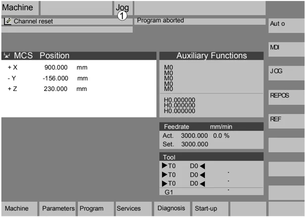
1 = operating mode
To select the modes:
- JOG
- MDA
- Automatic
press one of the keys shown on the left on the machine control panel or the corresponding vertical softkey, which you can access via the "Menu Select" key:
- JOG
- MDA
- Automatic
When a mode is selected, the LED next to the selection key on the MCP lights up. The same status is signaled in the mode field on the screen.

4
Machine operating area
4.1 CNC data structure
Additional information
The main screen of the selected mode appears on the screen.
If a mode change is not possible, please contact your installation engineer, the machine-tool manufacturer or our service personnel. In many cases, a mode change is enabled for trained personnel only on safety grounds. To provide this type of protection, the control system offers a facility for disabling or enabling mode changes.
Function Manual Basic Functions: Mode group, channel, program operation, reset response (K1)


4.2 General functions and displays
4.2.1 Start/stop/abort/continue part program
Function
The following section describes how to start and stop part programs and to resume them after they have been aborted.
Sequence of operations
"AUTO" mode is selected in the "Machine" operating area.
Prerequisite No alarms are pending. The program is selected. Feed enable is active. Spindle enable is set.
Start part program: The part program is started and executed.
Stop/abort part program: The program run is interrupted, but can be restarted with "NC Start". The current program is aborted.
Continue part program: After interrupting the program ("NC Stop") you can retract the tool from the contour in the mode ("JOG"). The control saves the coordinates of the point of interruption. The distances traversed are displayed.
Repositioning: Select the "Machine" operating area.
Select "JOG" mode.
Press the "Repos" key to reposition the tool on the contour.
Turning machine: Press the "+X" or "-X" key.
 Cycle Start
 Cycle Stop
Reset
 Machine
JOG
 Repos
+X -X
...
4 01/2008 Machine operating area 4.2 General functions and displays 4
Milling machine: Select the axis to be traversed and
then press the "-" or "+" key.
Traverse the axes to the point of interruption.
4.2.2 Displaying the program level
Function
If subprograms are called while a part program is running, the block numbers for the main program and subprograms together with their pass number (P) can be displayed.
Sequence of operations
"AUTO" mode is selected in the "Machine" operating area.
When you press the "Program level" softkey, the window headed "Program level" appears instead of the "Current block" window. The softkey labeling changes to "Current block".
During execution of a part program, the block numbers for the main program and subprograms, together with their pass number (P), are displayed in the "Program level" window. The main level is always visible, a nesting depth of up to 12 can be displayed.
Current block When you press the "Current block" softkey, the "Current block" window containing the program blocks of the current part program is displayed again.

4 Machine operating area 01/2008 4
4.2 General functions and displays
4.2.3 Switching over the machine/workpiece coordinate system (MCS/WCS)
Function
The display can be toggled between the machine and workpiece coordinate systems by means of special key "MCS/WCS" on the MCP or via softkeys (depending on MCP model and user program). The actual position display for the distance-to-go and the corresponding axes change.
Machine axes Machine axes are axes that actually exist on the machine and have been parameterized during installation.
Geometry axes and special axes These are the axes programmed in the part program. Geometry axes and special axes are offset by the selected work offset relative to the machine axes. Three is the maximum number of Cartesian geometry axes.
MCS The machine coordinate system (= MCS) refers to the coordinates of the machine axes, i.e., all machine axes are displayed in the machine coordinate system.
WCS An offset (e.g., work offset, rotation) can be used to set up a relationship, e.g., with the workpiece clamp. This relationship defines the position of the workpiece coordinate system (= Work) in relation to the machine coordinate system. The workpiece is always represented in a Cartesian coordinate system. All geometry axes and special axes are displayed in the workpiece coordinate system.
Machine manufacturer
Machine data are used to define whether the programmed frames are to be calculated when displaying the WCS (settable zero system = SZS display). Please consult the documentation provided by the machine manufacturer!
4
Machine operating area
4.2 General functions and displays
4
Graphical display of the active coordinate system
Example:
Meaning of the symbols (from left to right):
Display of the following transformations:
- Designation of the active work offset (default value: G500).
- Rotation of the geometry axes involved. Without rotation the symbol is invisible.
- Mirroring of the geometry axes involved. Without mirroring the symbol is invisible.
- Scaling of the geometry axes involved. Without scaling the symbol is invisible.
Sequence of operations
"JOG" mode is selected in the "Machine" operating area.
Act. val. MCS
The actual values of the machine axes and their positions are displayed. The softkey label changes to "Act. val. WCS".
The machine coordinate system comprises all the physically existing machine axes. Reference points, tool and pallet change points are defined in the Machine Coordinate System.
Act. val. WCS
When you press the "Act. val. WCS" softkey, the geometry and special axes plus their positions appear in the "Position" window. The softkey label changes to "Act. val. MCS". The workpiece coordinate system is assigned to a specific workpiece. Settings in the NC program refer to the WCS.
WCS MCS
- You can also toggle between the workpiece and machine coordinate systems by pressing the "WCS/MCS" key on the MCP.
- The number of places displayed after the decimal point and units of measurement can be set in machine data.
/PG/ Programming Manual Fundamentals
4.2.4 Displaying several transverse axes
Function
Most lathes use one transverse axis in the channel. Special lathes with several transverse axes in the channel are also supported. Dimensions can be entered and displayed for the diameter simultaneously for known transverse axes in the channel.
Rotary axes are not permitted to serve as transverse axes.
The transverse axes are displayed in three statuses:
- Axis with constant cutting velocity (G96/G961/G962) where the radius is displayed.
- Axis with constant cutting velocity and where the diameter actual value is displayed.
- Axis where the actual diameter is displayed. Is displayed if the values DIAMON or DIAM90 are active in group G29.
One transverse axis
Constant cutting velocity (G96/G961/G962) is only possible for a transverse axis as geometry axis. When using a transverse axis in the channel – defined using the channel machine data MD 20100: DIAMETER_AX_DEF – there are no changes regarding programming and setting of the machine data.
Several transverse axes
The axis machine data MD 30460: BASE_FUNCTION_MASK bit 2 allows the definition of additional transverse axes, for which axis-specific diameter programming.
MD 30460:
- Bit2 = 0 Axis-specific diameter programming not permitted.
- Bit2 = 1 Axis-specific diameter programming permitted. This setting is only permitted for linear axes (neither rotary axes nor spindles).
An axis can be simultaneously defined in MD 20100 and in MD 30460 bit2.
4
Machine operating area
4.2 General functions and displays
Example
The axis Y is a transverse axis where the actual diameter is displayed and axis Z is G96 transverse axis where the actual diameter is displayed.
Actual value window in the machine operator area:
G500
References
Programming Manual, Fundamentals "Special turning functions"
4.2.5 Displaying axis feedrates
Function
In operating mode "JOG", "MDA" or "AUTO", you can display the current feedrate, residual path information and the associated override data.
Sequence of operations
"JOG" mode is selected in the "Machine" operating area.
Press the "Axis feedrate" softkey:
• With "Machine" the feed window is displayed with the current feedrates and distance-to-go information as well as the associated override.
• With "Work" the feed window for the axes taking part in the interpolation is displayed with the current feed and the distance- to-go information with path override; for the remaining axes the current feed and distance-to-go information is displayed with single-axis override.
You can use the "Page" keys to display other axes if required.
4 Machine operating area 01/2008 4
4.2 General functions and displays
4.2.6 Display G functions, transformations and swivel data
Function Active G functions and transformations in the currently active channel can be displayed.
Sequence of operations "AUTO"/"MDA"/"JOG" mode is selected in the "Machine" operating area.
The window "G Functions + Transformations" with the active G functions and transformations is displayed.
Using the "Page" keys you can scroll up and down to display other G functions.
PAGE UP or PAGE DOWN
Additional information Every G group has a fixed location. The group number (no.) and the current G function of the G groups are displayed only if a G function is active.
References /PG/ Programming Manual, Fundamentals
Swivel data status display Prerequisite: The swivel function (CYCLE800) has been set up by the machine manufacturer.
The active swivel data record (orientable toolholder TOOLCARRIER) is displayed concurrently with the transformations.
The following values are displayed: TCARR = 1 ... n* *n is the maximum number of swivel data items that have been set up (TOOLCARRIER) and are active.
References /PGZ/ Programming Manual, Cycles: Chapter "Swiveling"
4
Machine operating area
4.2 General functions and displays
4
4.2.7 Displaying auxiliary functions
Function Auxiliary functions that are active in the selected channel can be displayed.
Sequence of operations "Auto"/"MDA"/"JOG" mode is selected in the "Machine" operating area.
Display aux. fct. The "Auxiliary Functions" window appears on the screen. Up to 5 M functions and 3 H functions can be displayed.
4.2.8 Displaying modal M functions
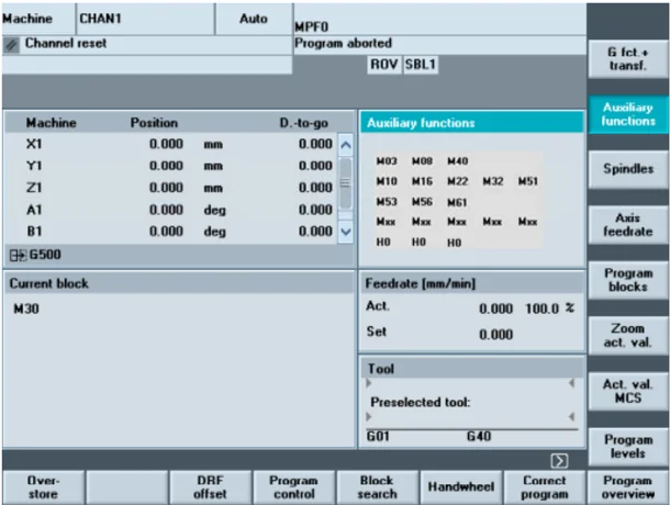
Function Modal M functions remain active until they are deleted or overwritten by another command. M functions are not merely displayed block-by-block, but also remain visible for as long as they are active. M functions are grouped together (in the same way as G functions, for example), but it is not necessary to display every group.
Display the statuses of modal M functions The statuses of M functions are displayed as follows:
M function active
M function retrieved during search, but not yet output to PLC
M22 M function output to PLC but not yet acknowledged (yellow text on black background signifies: Wait)
4 Machine operating area 01/2008 4
4.2 General functions and displays
Window division
5 lines are displayed:
- Line: Standard M functions: M03/M04/M05/M19, M7/M8, M40/M41/M42/M43/M44/M45
- Line: customized, grouped together M functions
- Line: customized, grouped together M functions
- Line: non-grouped M functions
- Line: H functions
The lines are oriented toward the actual value positions. A maximum of 5 M functions or 5 H functions can be displayed in each line.
Example:
4.2.9 Displaying spindles
Function
The current spindle values (actual speed, setpoint speed, position on oriented spindle stop and spindle override) can be displayed.
Sequence of operations
"AUTO"/"MDA"/"JOG" mode is selected in the "Machine" operating area.
The "Spindle" window appears on the screen. The window contains the spindle setpoint and actual value, position, setting of spindle override switch and spindle output.
Using the "Page" keys you can scroll up or down to display other spindles - if any are configured.
Additional information
- The "Spindle" window is only displayed if at least one spindle is configured.
- If a master spindle is configured, this is automatically displayed in the spindle window, even if it is not the first spindle.
The following spindle states are output as symbols for the spindles displayed in the spindle window:
- "Spindle STOP"
- "Spindle is not enabled"
- "Spindle direction of rotation counter-clockwise" or "... clockwise" (=spindle running)

4 Machine operating area 01/2008 4
4.2 General functions and displays
4.2.10 Handwheel

Function Using the "Handwheel" function, you can assign an axis to the handwheels and activate them.
Sequence of operations "JOG" mode is selected in the "Machine" operating area.
The "Handwheel" window appears on the screen.
Position the cursor on the handwheel of your choice (1-3).
 An axis identifier is suggested in the "Axis" field. All other existing axes can be selected via the "Toggle" key. The settings are accepted immediately and an axis is assigned to each handwheel (1-3).
 Every time you press the "Toggle" key in the "Active" field you activate or deactivate enabling of the relevant handwheel. The settings become active immediately.
When you turn the handwheel, the assigned axis traverses by the number of increments that have been set for it (Inc keys).
 Machine manufacturer
The machine manufacturer is responsible for the design of handwheels. Operation may therefore differ from the explanation above. Please refer to the machine manufacturer's documentation!
4
Machine operating area
4.2 General functions and displays
4
4.2.11 Status of the synchronized actions
Function
Status information (such as "enabled", "disabled", etc.) can be displayed here to support commissioning of synchronized actions. References: /PGA/, Programming Guide Advanced, Chapter "Synchronized actions"
Sequence of operations
"AUTO"/"MDA"/"JOG" mode is selected in the "Machine" operating area.
Press the "ETC" key followed by
the "Synchroniz. actions" softkey. The display "Status of synchronized actions" appears.
Synchron. actions
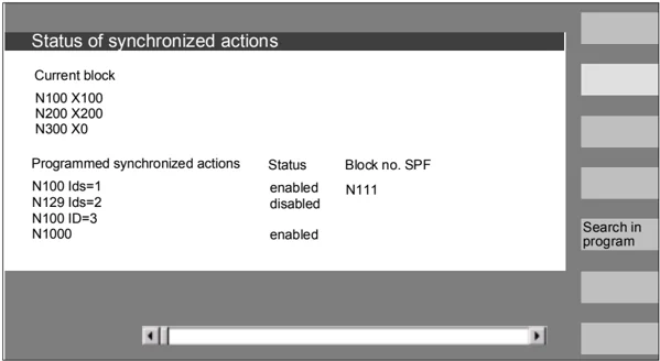
The display shows:
- "Current block" column: Current section of selected part program: Preceding, current and following block
- "Programmed synchronized actions" column: The programmed synchronized actions are listed block by block with block number (static/modal actions are listed together with the number of the synchronized action)
4 Machine operating area 01/2008 4
4.2 General functions and displays
- "Status" column:
- " " (no information given) the condition is checked in the interpolation cycle.
- "disabled" LOCK was set from the PLC for the synchronized action
- "active" The action is currently being executed. If the instruction part of a programmed synchronized action starts a subprogram/cycle, the current block number of the cycle is additionally displayed in the "Block number SPF" column.
A window opens: Here you must enter the system variable/synchronized action of your choice. The control searches the current or an additionally specified program for synchronized actions which match the current block and synchronized action numbers. If the control finds matching program blocks, the associated condition and instruction parts are also shown on the main screen along with the other data.
Press RECALL to return to the "Automatic" main screen.

4
Machine operating area
4.2 General functions and displays
4
4.2.12 Preset
Function Resetting the actual value A new position value is entered for the current axis positions.
Danger After the actual value has been reset, none of the protection zones or software limit switches are operative! The protection zones and software limit switches are only reactivated following another reference point approach.
The "Preset" function can be used to redefine the control zero in the machine coordinate system. The preset values act on machine axes. Axes do not move when "Preset" is active.
Machine manufacturer See machine manufacturer's specifications.
Sequence of operations "JOG" mode is selected in the "Machine" operating area.
Preset The "Preset" window appears on the screen.
Enter the new actual value, which must in future correspond to the current axis position, for each individual axis. By doing so, you are redefining the control zero in the MCS. When the control zero is redefined, the tool change point, for example, also changes.
Additional information
Machine manufacturer The "Preset" function can be disabled by means of protection levels (keylock switch position).
4 Machine operating area 01/2008 4 4.2 General functions and displays
4.2.13 Setting the actual value
Function
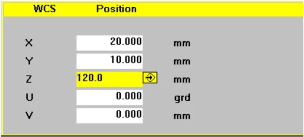
The "Set actual value" function is now available via display machine data 9422 as a functional alternative to the existing "Preset" function. The "Set actual value" function can be used only if the control is operating in the workpiece coordinate system. The functions are stored under the same softkey. This function sets the workpiece coordinate system to a defined actual coordinate. The resultant offset between the old actual value and the newly entered WCS actual value is computed in the system frame or basic frame defined by the machine manufacturer.
Machine manufacturer
See machine manufacturer's specifications.
References Commissioning Manual HMI Advanced
Sequence of operations
Prerequisite: The function can only be invoked when G500 and Work (WCS) are active.
The new position setpoint of the axes in the workpiece coordinate system can be entered using "Set actual value" in the actual value window. When you transfer a value to the system by pressing "Input", the deviation from the current actual value is entered in the basic frame or system frame. The new actual value is displayed in the "Position" column.

Using "Abort", you can undo the entire offset entered up to now and exit the input screen.
4-108 © Siemens AG 2008 All rights reserved.
4 01/2008 Machine operating area 4.2 General functions and displays 4
4.2.14 Inch \leftrightarrow Metric switchover
Function
The control can work with imperial inches or metric units of measurement. You can switch between imperial inches and metric units of measurement in the "Machine" operating area. The control converts the values accordingly.
In order to convert the channel-specific values in the machine date, display machine data 9014 must be set to 1.
Machine manufacturer
The switchover is only possible if:
- The corresponding machine data have been set.
- All channels are in the Reset state.
- Axes are not traversing with JOG, DRF or PLC control.
- Constant grinding wheel peripheral speed (GWPS) is not active.
Display machine data 9011 is used to define the display resolution for the imperial units of measurement (inches).
Actions such as mode change or part program start are disabled for the duration of the switchover.
Sequence of operations
"AUTO"/"MDI"/"JOG" mode is selected in the "Machine" operating area.
Press the "ETC" key followed by
the "Switch to metric" softkey.
When the measuring system is changed, all length-related parameters are automatically converted to the new measuring system from the perspective of the user.
If the switchover cannot be performed, this is indicated by a message on the user interface.
References
Function Manual Fundamentals, G2 Chapter "Metric/inch measuring system"
4 Machine operating area 01/2008
4.2 General functions and displays
! image of warning triangle icon in left margin
Warning
If several NCUs are linked by NCU-link, the switchover has the same effect on all linked NCUs. If the prerequisites for a switchover are not fulfilled on one of the NCUs linked, no switchover will take place on none of the NCUs. It is assumed that interpolations between several NCUs will take place on the existing NCUs, whereby the interpolations can provide correct results only if the same unit systems are used.
References
Function Manual Extended Functions, Distributed Systems (B3)

4.3 Reference point approach
Function
The "Ref Point" function ensures that the control and machine are synchronized after Power ON. Before a reference point approach can be carried out, the axes must be located at positions (if necessary, traversed to these positions using the axis keys/handwheel) from where the machine reference point can be approached without collision. If reference point approach is called from a part program, all axes can be traversed simultaneously.
Reference point approach can only be performed by machine axes. The actual value display does not match the real position of the axes when the control is switched on.
Caution
- If the axes are not safely positioned, you must traverse them to safe positions in "JOG" or "MDI" mode.
- You must follow the axis motions directly on the machine!
- Ignore the actual value display until the axes have been referenced!
- The software limit switches are not active!
Sequence of operations
"JOG" or "MDI" is selected in the "Machine" operating area. The channel for reference point approach is selected.

The "Ref Point" machine function is selected.
Turning machine: Press the "Axis" keys.
Milling machine: Select the axis to be traversed and then press the "+" or "-" key.
4 Machine operating area 01/2008 4
4.3 Reference point approach

Machine manufacturer
The selected axis moves to the reference point. The direction and sequence is defined by the machine manufacturer in the PLC program. If you have pressed the wrong direction key, the action is not accepted and the axes do not move. The display shows the reference point value.
No symbol is displayed for axes that are not referred to a reference point.
This symbol is displayed for axes that need to be referenced.
This symbol is shown next to an axis if it has been referenced.
The axis, once started, can be stopped before it reaches the reference point.
Turning machine: Press the "Axis" keys.
Milling machine: Select the axis to be traversed and then press the "+" or "-" key. The selected axis moves to the reference point.
Caution
The machine is synchronized as soon as the reference point is reached. The actual value display is set to the reference point value. The display is the difference between the machine zero and the slide reference point. From now on, path limits, such as software limit switches, are active.
You can end the function by selecting another operating mode ("JOG", "MDI" or "Automatic").
- All axes of a mode group can approach the reference point simultaneously (depending on the PLC program of the machine-tool manufacturer).
- The feedrate override is active.
4 01/2008
Machine operating area 4.3 Reference point approach 4
Machine manufacturer
Your machine manufacturer will instruct you how to select axes if you intend to enter more than nine.
Additional information
The sequence in which axes must be referenced can be defined by the machine-tool manufacturer.
The NC cannot be started in Automatic mode until all axes with a defined reference point (see machine data MD) have actually reached this point.
4.4 JOG mode
4.4.1 Function and main screen
Function
In manual mode you can:
- Synchronize the control measuring system with the machine (reference point approach),
- Set up the machine, i.e., activate manually-controlled motions on the machine using the keys and handwheels provided on the machine control panel.
- Activate manually-controlled motions on the machine using the keys and handwheels provided on the machine control panel while a part program is being interrupted.
The following "JOG" main screen is displayed when you press the "Menu Select" key
followed by the "JOG" key.
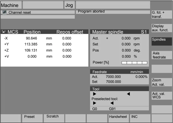
The "JOG" main screen contains values relating to position, feedrate, spindle and tool.