Assigning Addresses and Initial Values in the Data Block Editor
The data block editor allows you to make initial data assignments to V memory (variable memory) only. You can make assignments to bytes, words, or double words of V memory. Comments are optional.
The data block editor is a free-form text editor; that is, no specific fields are defined for particular types of information. After you finish typing a line and press the Enter key, the data block editor formats the line (aligns columns of addresses, data, comments; capitalizes V memory addresses) and redisplay it. Pressing CTRL-ENTER, after completing an assignment line, auto-increments the address to the next available address.
 Figure 5-7 Data Block Editor
The data block editor assigns an appropriate amount of V memory based on your previous address allocations and the size (byte, word, or double word) of the data value(s).
The first line of the data block must have an explicit address assignment. Subsequent lines can have explicit or implicit address assignments. An implicit address assignment is made by the editor when you type multiple data values after a single address assignment, or type a line that contains only data values.
The data block editor accepts uppercase or lowercase letters and allows commas, tabs, or spaces to serve as separators between addresses and data values.
Using the Symbol Table for Symbolic Addressing of Variables
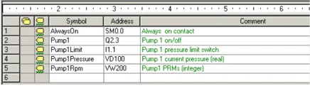
The symbol table allows you to define and edit the symbols that can be accessed by the symbolic name anywhere in your program. You can create multiple symbol tables. There is also a tab in the symbol table for system-defined symbols that you can use in your program. The symbol table is also referred to as the global variable table.
You can identify the operands of the instructions in your program absolutely or symbolically. An absolute reference uses the memory area and bit or byte location to identify the address. A symbolic reference uses a combination of alphanumeric characters to identify the address.
For SIMATIC programs, you make global symbol assignments by using the symbol table. For IEC programs, you make global symbol assignments by using the global variable table.
To assign a symbol to an address:
- Click on the Symbol Table icon in the navigation bar to open the symbol table.
- Enter the symbol name (for example, Input1) in the Symbol Name column. The maximum symbol length is 23 characters.
- Enter the address (for example, I0.0) in the Address column.
- For an IEC global variable table, enter a value in the Data Type column or select one from the list box.
You can create multiple symbol tables; however, you cannot use the same string more than once as a global symbol assignment, neither within a single table nor among several tables.
\begin{tabular}{|l|l|l|l|} \hline & Symbol & Address & Comment \ \hline 1 & AlwaysOn & SM0.0 & Always on contact \ \hline 2 & Pump1 & Q2.3 & Pump 1 on/off \ \hline 3 & Pump1Limit & I1.1 & Pump 1 pressure limit switch \ \hline 4 & Pump1Pressure & VD100 & Pump 1 current pressure (real) \ \hline 5 & Pump1Rpm & VW200 & Pump1 PRMs (integer) \ \hline 6 & & & \ \hline \end{tabular}
Figure 5-8 Symbol Table
62
Programming Concepts, Conventions, and Features Chapter 5
Using Local Variables
You can use the local variable table of the program editor to assign variables that are unique to an individual subroutine or interrupt routine. See Figure 5-9.
Local variables can be used as parameters that are passed in to a subroutine and they increase the portability or reuse of a subroutine.
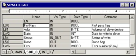
Figure 5-9 Local Variable Table \begin{tabular}{|l|l|l|l|l|} \hline & Name & Var Type & Data Type & Comment \ \hline & EN & IN & BOOL & \ \hline L0.0 & FirstPass & IN & BOOL & First pass flag \ \hline LB1 & Addr & IN & BYTE & Address of slave device \ \hline Lw2 & Data & IN & INT & Data to write to slave \ \hline LB4 & Status & IN_OUT & BYTE & Status of write \ \hline L5.0 & Done & OUT & BOOL & Done flag \ \hline Lw6 & Error & OUT & WORD & Error number (if any) \ \hline \end{tabular}
Using the Status Chart to Monitor Your Program
A status chart allows you to monitor or modify the values of the process variables as your S7-200 runs the control program. You can track the status of program inputs, outputs, or variables by displaying the current values. The status chart also allows you to force or change the values of the process variables.
You can create multiple status charts in order to view elements from different portions of your program.
To access the status chart, select the View > Component > Status Chart menu command or click the Status Chart icon in the navigation bar.
When you create a status chart, you enter addresses of process variables for monitoring. You cannot view the status of constants, accumulators, or local variables. You can display a timer or counter value either as a bit or as a word. Displaying the value as a bit shows the status of the timer or counter bit; displaying the value as a word shows the timer or counter value.
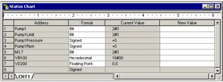
Figure 5-10 Status Chart \begin{tabular}{|l|l|l|l|l|} \hline & Address & Format & Current Value & New Value \ \hline 1 & Pump1 & Bit & 240 & \ \hline 2 & Pump1Limit & Bit & 240 & \ \hline 3 & Pump1Pressure & Signed & +0 & \ \hline 4 & Pump1Rpm & Signed & +0 & \ \hline 5 & M5.7 & Bit & 240 & \ \hline 6 & VB100 & Hexadecimal & 16#00 & \ \hline 7 & VD200 & Floating Point & 0.0 & \ \hline 8 & & Signed & & \ \hline \end{tabular}
To build a status chart and monitor the variables:
- Enter the address for each desired value in the Address field.
- Select the data type in the Format column.
- To view the status of the process variables in your S7-200, select the Debug > Chart Status menu command.
- To continuously sample the values, or to perform a single read of the status, click the button on the toolbar. The Status Chart also allows you to modify or force values for the different process variables.
You can insert additional rows in your Status Chart by selecting the Edit > Insert > Row menu command.
Tip
You can create multiple status charts to divide the variables into logical groups so that each group can be viewed in a shorter and separate status chart.
Creating an Instruction Library
STEP 7-Micro/WIN allows you either to create a custom library of instructions, or to use a library created by someone else. See Figure 5-11.
To create a library of instructions, you create standard STEP 7-Micro/WIN subroutine and interrupt routines and group them together. You can hide the code in these routines to prevent accidental changes or to protect the technology (know-how) of the author.
To create an instruction library, perform the following tasks:
- Write the program as a standard STEP 7-Micro/WIN project and put the function to be included in the library into subroutines or interrupt routines.
- Ensure that all V memory locations in the subroutines or interrupt routines have been assigned a symbolic name. To minimize the amount of V memory that the library requires, use sequential V memory locations.
- Rename the subroutines or interrupt routines to the names that you want to appear in the instruction library.
- Select the File > Create Library menu command to compile the new instruction library.
For more information about creating libraries, refer to the online help for STEP 7-Micro/WIN.
 Figure 5-11 Instruction Tree with Libraries
Use the following procedure to access an instruction in an instruction library:
- Add the Libraries directory to the instruction tree by selecting the File > Add Libraries menu command.
- Select the specific instruction and insert it into your program (as you would any standard instruction).
If the library routine requires any V memory, STEP 7-Micro/WIN prompts you when the project is compiled to assign a block of memory. Use the Library Memory Allocation dialog box to assign blocks of memory.
Features for Debugging Your Program
STEP 7-Micro/WIN provides the following features to help you debug your program:
☐ Bookmarks in your program to make it easy to move back and forth between lines of a long program.
☐ Cross Reference table allow you to check the references used in your program.
☐ RUN-mode editing allows you to make small changes to your program with minimal disturbance to the process controlled by the program. You can also download the program block when you are editing in RUN mode.
For more information about debugging your program, refer to Chapter 8.
64
S7-200 Instruction Set
This chapter describes the SIMATIC and IEC 1131 instruction set for the S7-200 Micro PLCs.
I n This Chapter
- Conventions Used to Describe the Instructions . . . . . . . . . . . . . . . . . . . . . . . . . . . . . . . . . . . . . . . . . . . . . . . . . . . . . . . . . . . . . . . . . . . . . . . . . . . . . . . . . . . . . . . . . . . . . . . . . . . . . . . . . . . . . . . . . . . . . . . . . . . . . . . . . . . . . . . . . . . . . . . . . . . . . . . . . . . . . . . . ........ 67
- S7-200 Memory Ranges and Features . . . . . . . . . . . . . . . . . . . . . . . . . . . . . . . . . . . . . . . . . . . . . . . . . . . . . . . . . . . . . . . . . . . . . . . . . . . . . . . . . . . . . . . . . . . . . . . . . . . . . ........ 68
- Bit Logic Instructions . . . . . . . . . . . . . . . . . . . . . . . . . . . . . . . . . . . . . . . . . . . . . . . . . . . . . . . . . . . . . . . . . . . . . . . . . . . . . . . . . . . . . . . . . . . . . . . . . . . . . . . . . . . . . ........

- Program Control Instructions . . . . . . . . . . . . . . . . . . . . . . . . . . . . . . . . . . . . . . . . . . . . . . . . . . . . . . . . . . . . . . . . . . . . . . . . . . . . . . . . . . . . . . . . . . . . . . . . . . . . . . . . . . . . . . . . . . . . . . . . . . . . . . . . . . . . . . . . . . . . . . . . . . . . . . . . . . . . . . . . . . . . . . . . . . . . . . . . . . . . . . . . . . . . . . . . . . . . . . . . . . . . . . . . . . . . ........ 167
- Conditional End . . . . . . . . . . . . . . . . . . . . . . . . . . . . . . . . . . . . . . . . . . . . . . . . . . . . . . . . . . . . . . . . . . . . . . . . . . . . . . . . . . . . . . . . . . . . . . . . . . . . . . . . . . . . . . . . ........ 167
- Stop . . . . . . . . . . . . . . . . . . . . . . . . . . . . . . . . . . . . . . . . . . . . . . . . . . . . . . . . . . . . . . . . . . . . . . . . . . . . . . . . . . . . . . . . . . . . . . . . . . . . . . . . . . . . . . . . . . . . . . ........
Conventions Used to Describe the Instructions
Figure 6-1 shows a typical description for an instruction and points to the different areas used to describe the instruction and its operation. The illustration of the instruction shows the format in LAD, FBD, and STL. The operand table lists the operands for the instruction and shows the valid data types, memory areas and sizes for each operand.
EN/ENO operands and data types are not shown in the instruction operand table because the operands are the same for all LAD and FBD instructions.
For LAD: EN and ENO are power flow and are BOOL data types.
For FBD: EN and ENO are I, Q, V, M, SM, S, T, C, L, or power flow and are BOOL data types.
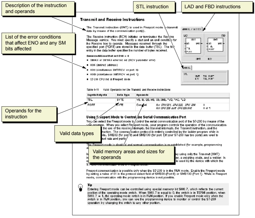
Figure 6-1 Instruction Descriptions
S7-200 Memory Ranges and Features
Table 6-1 Memory Ranges and Features for the S7-200 CPUs
| Description | CPU 221 | CPU 222 | CPU 224 | CPU 224XP CPU 224XPsi | CPU 226 |
|---|---|---|---|---|---|
| User program size with run mode edit without run mode edit | 4096 bytes 4096 bytes | 4096 bytes 4096 bytes | 8192 bytes 12288 bytes | 12288 bytes 16384 bytes | 16384 bytes 24576 bytes |
| User data size | 2048 bytes | 2048 bytes | 8192 bytes | 10240 bytes | 10240 bytes |
| Process-image input register | I0.0 to I15.7 | I0.0 to I15.7 | I0.0 to I15.7 | I0.0 to I15.7 | I0.0 to I15.7 |
| Process-image output register | Q0.0 to Q15.7 | Q0.0 to Q15.7 | Q0.0 to Q15.7 | Q0.0 to Q15.7 | Q0.0 to Q15.7 |
| Analog inputs (read only) | AIW0 to AIW30 | AIW0 to AIW30 | AIW0 to AIW62 | AIW0 to AIW62 | AIW0 to AIW62 |
| Analog outputs (write only) | AQW0 to AQW30 | AQW0 to AQW30 | AQW0 to AQW62 | AQW0 to AQW62 | AQW0 to AQW62 |
| Variable memory (V) | VB0 to VB2047 | VB0 to VB2047 | VB0 to VB8191 | VB0 to VB10239 | VB0 to VB10239 |
| Local memory (L)¹ | LB0 to LB63 | LB0 to LB63 | LB0 to LB63 | LB0 to LB63 | LB0 to LB63 |
| Bit memory (M) | M0.0 to M31.7 | M0.0 to M31.7 | M0.0 to M31.7 | M0.0 to M31.7 | M0.0 to M31.7 |
| Special Memory (SM) Read only | SM0.0 to SM179.7 SM0.0 to SM29.7 | SM0.0 to SM299.7 SM0.0 to SM29.7 | SM0.0 to SM549.7 SM0.0 to SM29.7 | SM0.0 to SM549.7 SM0.0 to SM29.7 | SM0.0 to SM549.7 SM0.0 to SM29.7 |
| Timers Retentive on-delay 1 ms 10 ms 100 ms On/Off delay 1 ms 10 ms 100 ms | 256 (T0 to T255) T0, T64 T1 to T4, and T65 to T68 T5 to T31, and T69 to T95 T32, T96 T33 to T36, and T97 to T100 T37 to T63, and T101 to T255 | 256 (T0 to T255) T0, T64 T1 to T4, and T65 to T68 T5 to T31, and T69 to T95 T32, T96 T33 to T36, and T97 to T100 T37 to T63, and T101 to T255 | 256 (T0 to T255) T0, T64 T1 to T4, and T65 to T68 T5 to T31, and T69 to T95 T32, T96 T33 to T36, and T97 to T100 T37 to T63, and T101 to T255 | 256 (T0 to T255) T0, T64 T1 to T4, and T65 to T68 T5 to T31, and T69 to T95 T32, T96 T33 to T36, and T97 to T100 T37 to T63, and T101 to T255 | 256 (T0 to T255) T0, T64 T1 to T4, and T65 to T68 T5 to T31, and T69 to T95 T32, T96 T33 to T36, and T97 to T100 T37 to T63, and T101 to T255 |
| Counters | C0 to C255 | C0 to C255 | C0 to C255 | C0 to C255 | C0 to C255 |
| High-speed counters | HC0 to HC5 | HC0 to HC5 | HC0 to HC5 | HC0 to HC5 | HC0 to HC5 |
| Sequential control relays (S) | S0.0 to S31.7 | S0.0 to S31.7 | S0.0 to S31.7 | S0.0 to S31.7 | S0.0 to S31.7 |
| Accumulator registers | AC0 to AC3 | AC0 to AC3 | AC0 to AC3 | AC0 to AC3 | AC0 to AC3 |
| Jumps/Labels | 0 to 255 | 0 to 255 | 0 to 255 | 0 to 255 | 0 to 255 |
| Call/Subroutine | 0 to 63 | 0 to 63 | 0 to 63 | 0 to 63 | 0 to 127 |
| Interrupt routines | 0 to 127 | 0 to 127 | 0 to 127 | 0 to 127 | 0 to 127 |
| Positive/negative transitions | 256 | 256 | 256 | 256 | 256 |
| PID loops | 0 to 7 | 0 to 7 | 0 to 7 | 0 to 7 | 0 to 7 |
| Ports | Port 0 | Port 0 | Port 0 | Port 0, Port 1 | Port 0, Port 1 |
¹ LB60 to LB63 are reserved by STEP 7-Micro/WIN, version 3.0 or later.
S7-200 Instruction Set Chapter 6
Table 6-2 Operand Ranges for the S7-200 CPUs
| Access Method | CPU 221 | CPU 222 | CPU 224 | CPU 224XP CPU 224XPsi | CPU 226 |
|---|---|---|---|---|---|
| Bit access (byte.bit) I | 0.0 to 15.7 | 0.0 to 15.7 | 0.0 to 15.7 | 0.0 to 15.7 | 0.0 to 15.7 |
| Q | 0.0 to 15.7 | 0.0 to 15.7 | 0.0 to 15.7 | 0.0 to 15.7 | 0.0 to 15.7 |
| V | 0.0 to 2047.7 | 0.0 to 2047.7 | 0.0 to 8191.7 | 0.0 to 10239.7 | 0.0 to 10239.7 |
| M | 0.0 to 31.7 | 0.0 to 31.7 | 0.0 to 31.7 | 0.0 to 31.7 | 0.0 to 31.7 |
| SM | 0.0 to 165.7 | 0.0 to 299.7 | 0.0 to 549.7 | 0.0 to 549.7 | 0.0 to 549.7 |
| S | 0.0 to 31.7 | 0.0 to 31.7 | 0.0 to 31.7 | 0.0 to 31.7 | 0.0 to 31.7 |
| T | 0 to 255 | 0 to 255 | 0 to 255 | 0 to 255 | 0 to 255 |
| C | 0 to 255 | 0 to 255 | 0 to 255 | 0 to 255 | 0 to 255 |
| L | 0.0 to 63.7 | 0.0 to 63.7 | 0.0 to 63.7 | 0.0 to 63.7 | 0.0 to 63.7 |
| Byte access IB | 0 to 15 | 0 to 15 | 0 to 15 | 0 to 15 | 0 to 15 |
| QB | 0 to 15 | 0 to 15 | 0 to 15 | 0 to 15 | 0 to 15 |
| VB | 0 to 2047 | 0 to 2047 | 0 to 8191 | 0 to 10239 | 0 to 10239 |
| MB | 0 to 31 | 0 to 31 | 0 to 31 | 0 to 31 | 0 to 31 |
| SMB | 0 to 165 | 0 to 299 | 0 to 549 | 0 to 549 | 0 to 549 |
| SB | 0 to 31 | 0 to 31 | 0 to 31 | 0 to 31 | 0 to 31 |
| LB | 0 to 63 | 0 to 63 | 0 to 63 | 0 to 63 | 0 to 63 |
| AC | 0 to 3 | 0 to 3 | 0 to 3 | 0 to 255 | 0 to 255 |
| KB (Constant) | KB (Constant) | KB (Constant) | KB (Constant) | KB (Constant) | KB (Constant) |
| Word access IW | 0 to 14 | 0 to 14 | 0 to 14 | 0 to 14 | 0 to 14 |
| QW | 0 to 14 | 0 to 14 | 0 to 14 | 0 to 14 | 0 to 14 |
| VW | 0 to 2046 | 0 to 2046 | 0 to 8190 | 0 to 10238 | 0 to 10238 |
| MW | 0 to 30 | 0 to 30 | 0 to 30 | 0 to 30 | 0 to 30 |
| SMW | 0 to 164 | 0 to 298 | 0 to 548 | 0 to 548 | 0 to 548 |
| SW | 0 to 30 | 0 to 30 | 0 to 30 | 0 to 30 | 0 to 30 |
| T | 0 to 255 | 0 to 255 | 0 to 255 | 0 to 255 | 0 to 255 |
| C | 0 to 255 | 0 to 255 | 0 to 255 | 0 to 255 | 0 to 255 |
| LW | 0 to 62 | 0 to 62 | 0 to 62 | 0 to 62 | 0 to 62 |
| AC | 0 to 3 | 0 to 3 | 0 to 3 | 0 to 3 | 0 to 3 |
| AIW | 0 to 30 | 0 to 30 | 0 to 62 | 0 to 62 | 0 to 62 |
| AQW | 0 to 30 | 0 to 30 | 0 to 62 | 0 to 62 | 0 to 62 |
| KW (Constant) | KW (Constant) | KW (Constant) | KW (Constant) | KW (Constant) | KW (Constant) |
| Double word access ID | 0 to 12 | 0 to 12 | 0 to 12 | 0 to 12 | 0 to 12 |
| QD | 0 to 12 | 0 to 12 | 0 to 12 | 0 to 12 | 0 to 12 |
| VD | 0 to 2044 | 0 to 2044 | 0 to 8188 | 0 to 10236 | 0 to 10236 |
| MD | 0 to 28 | 0 to 28 | 0 to 28 | 0 to 28 | 0 to 28 |
| SMD | 0 to 162 | 0 to 296 | 0 to 546 | 0 to 546 | 0 to 546 |
| SD | 0 to 28 | 0 to 28 | 0 to 28 | 0 to 28 | 0 to 28 |
| LD | 0 to 60 | 0 to 60 | 0 to 60 | 0 to 60 | 0 to 60 |
| AC | 0 to 3 | 0 to 3 | 0 to 3 | 0 to 3 | 0 to 3 |
| HC | 0 to 5 | 0 to 5 | 0 to 5 | 0 to 5 | 0 to 5 |
| KD (Constant) | KD (Constant) | KD (Constant) | KD (Constant) | KD (Constant) | KD (Constant) |
69
S7-200 Programmable Controller System Manual
Bit Logic Instructions
Contacts
Standard Contacts
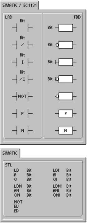
The Normally Open contact instructions (LD, A, and O) and Normally Closed contact instructions (LDN, AN, ON) obtain the referenced value from the memory or from the process-image register. The standard contact instructions obtain the referenced value from the memory (or process-image register if the data type is I or Q).
The Normally Open contact is closed (on) when the bit is equal to 1, and the Normally Closed contact is closed (on) when the bit is equal to 0. In FBD, inputs to both the And and Or boxes can be expanded to a maximum of 32 inputs. In STL, the Normally Open instructions Load, AND, or OR the bit value of the address bit to the top of the stack, and the Normally Closed instructions Load, AND, or OR the logical NOT of the bit value to the top of the stack.
Immediate Contacts
An immediate contact does not rely on the S7-200 scan cycle to update; it updates immediately. The Normally Open Immediate contact instructions (LDI, AI, and OI) and Normally Closed Immediate contact instructions (LDNI, ANI, and ONI) obtain the physical input value when the instruction is executed, but the process-image register is not updated.
The Normally Open Immediate contact is closed (on) when the physical input point (bit) is 1, and the Normally Closed Immediate contact is closed (on) when the physical input point (bit) is 0. The Normally Open instructions immediately Load, AND, or OR the physical input value to the top of the stack, and the Normally Closed instructions immediately Load, AND, or OR the logical NOT of the value of the physical input point to the top of the stack.
NOT Instruction
The Not instruction (NOT) changes the state of power flow input (that is, it changes the value on the top of the stack from 0 to 1 or from 1 to 0).
70
S7-200 Instruction Set Chapter 6
Positive and Negative Transition Instructions
The Positive Transition contact instruction (EU) allows power to flow for one scan for each off-to-on transition. The Negative Transition contact instruction (ED) allows power to flow for one scan for each on-to-off transition. For the Positive Transition instruction, detection of a 0-to-1 transition in the value on the top of the stack sets the top of the stack value to 1; otherwise, it is set to 0. For a Negative Transition instruction, detection of a 1-to-0 transition in the value on the top of the stack sets the top of the stack value to 1; otherwise, it is set to 0.
For run mode editing (when you edit your program in RUN mode), you must enter a parameter for the Positive Transition and Negative Transition instructions. Refer to Chapter 5 for more information about editing in RUN mode.
Table 6-3 Valid Operands for the Bit Logic Input Instructions \begin{tabular}{|l|l|l|} \hline Inputs/Outputs & Data Type & Operands \ \hline Bit & BOOL & I, Q, V, M, SM, S, T, C, L, Power Flow \ \hline Bit (immediate) & BOOL & I \ \hline \end{tabular}
As shown in Figure 6-2, the S7-200 uses a logic stack to resolve the control logic. In these examples, "iv0" to "iv7" identify the initial values of the logic stack, "nv" identifies a new value provided by the instruction, and "S0" identifies the calculated value that is stored in the logic stack.
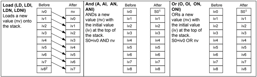
1 S0 identifies the calculated value that is stored in the logic stack. 2 After the execution of a Load, the value iv8 is lost.
Figure 6-2 Operations of the Contact Instructions.
Tip Because the Positive Transition and Negative Transition instructions require an on-to-off or an off-to-on transition, you cannot detect an edge-up or edge-down transition on the first scan. During the first scan, the S7-200 sets the state of the bit specified by these instructions. On subsequent scans, these instructions can then detect transitions for the specified bit.
71
Example: Contact Instructions
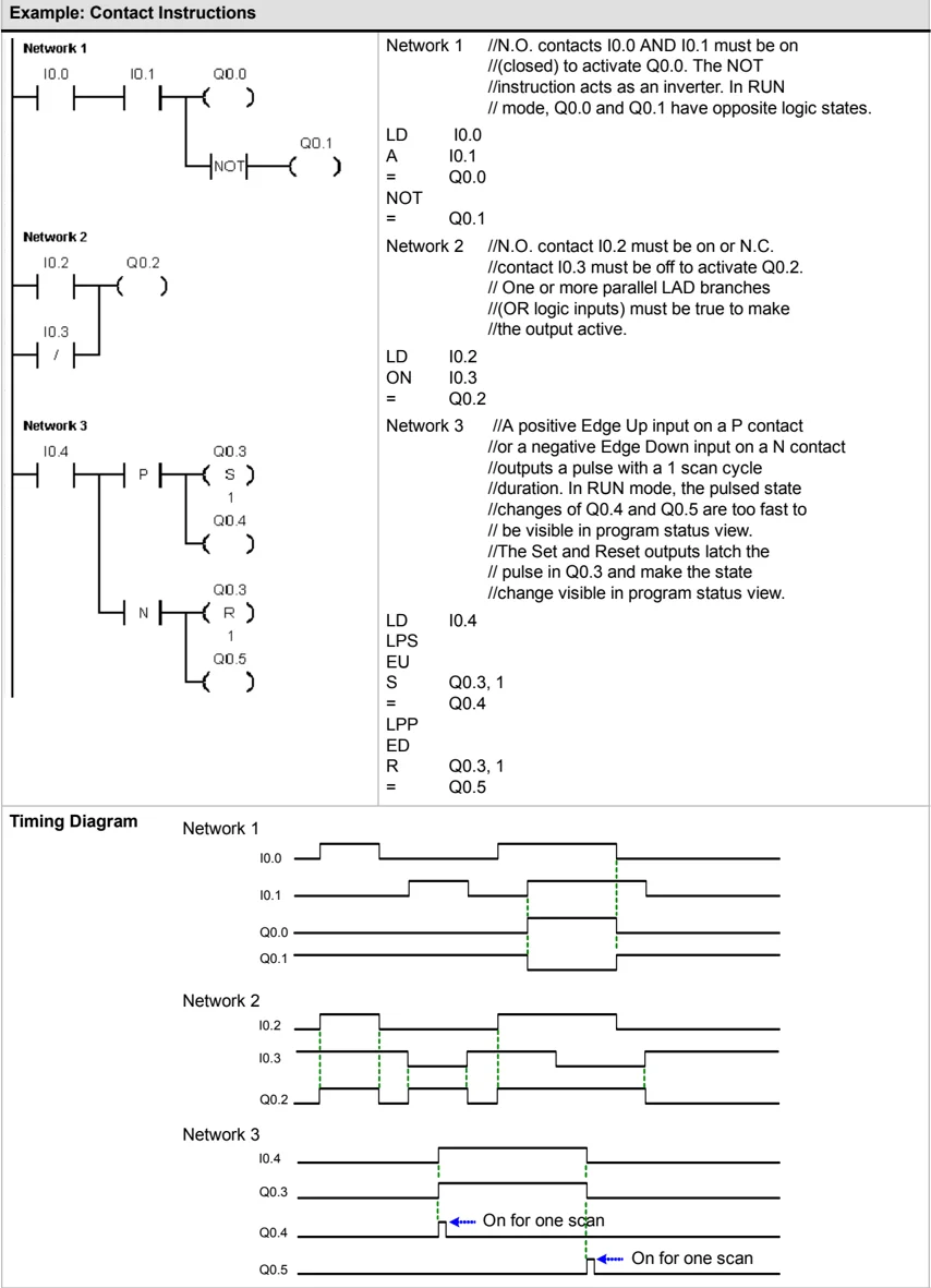
Timing Diagram
Coils
Output
The Output instruction (=) writes the new value for the output bit to the process-image register. When the Output instruction is executed, the S7-200 turns the output bit in the process-image register on or off. For LAD and FBD, the specified bit is set equal to power flow. For STL, the value on the top of the stack is copied to the specified bit.
Output Immediate
The Output Immediate instruction (=I) writes the new value to both the physical output and the corresponding process-image register location when the instruction is executed.
When the Output Immediate instruction is executed, the physical output point (Bit) is immediately set equal to power flow. For STL, the instruction immediately copies the value on the top of the stack to the specified physical output bit (STL). The "I" indicates an immediate reference; the new value is written to both the physical output and the corresponding process-image register location when the instruction is executed. This differs from the non-immediate references, which write the new value to the process-image register only.
Set and Reset
The Set (S) and Reset (R) instructions set (turn on) or reset (turn off) the specified number of points (N), starting at the specified address (Bit). You can set or reset from 1 to 255 points.
If the Reset instruction specifies either a timer bit (T) or counter bit (C), the instruction resets the timer or counter bit and clears the current value of the timer or counter.
Error conditions that set ENO = 0 ■ 0006 (indirect address) ■ 0091 (operand out of range)
Set Immediate and Reset Immediate
The Set Immediate and Reset Immediate instructions immediately set (turn on) or immediately reset (turn off) the number of points (N), starting at specified address (Bit). You can set or reset from 1 to 128 points immediately.
The "I" indicates an immediate reference; when the instruction is executed, the new value is written to both the physical output point and the corresponding process-image register location. This differs from the non-immediate references, which write the new value to the process-image register only.
Error conditions that set ENO = 0 ■ 0006 (indirect address) ■ 0091 (operand out of range)
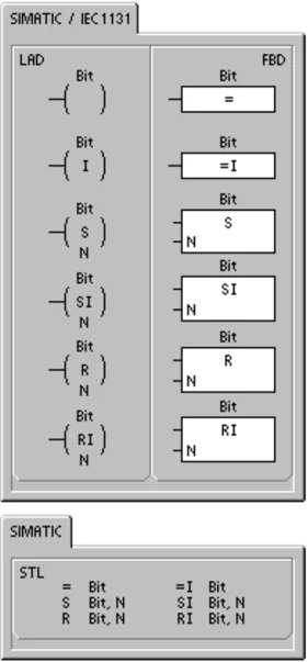
Table 6-4 Valid Operands for the Bit Logic Output Instructions \begin{tabular}{|l|l|l|} \hline Inputs/Outputs & Data Type & Operands \ \hline Bit & BOOL & I, Q, V, M, SM, S, T, C, L \ \hline Bit (immediate) & BOOL & Q \ \hline N & BYTE & IB, QB, VB, MB, SMB, SB, LB, AC, *VD, *LD, *AC, Constant \ \hline \end{tabular}
Example: Coil Instructions
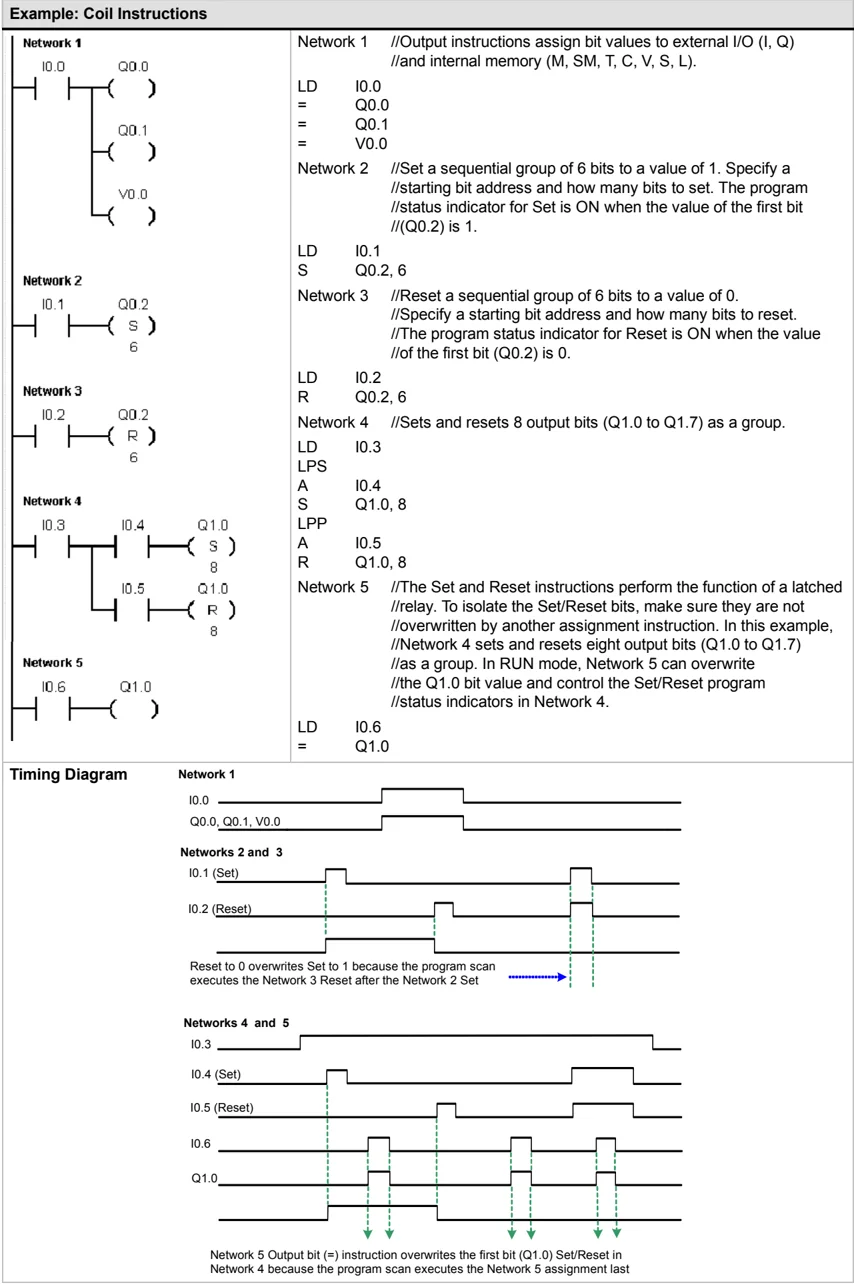
Network 1 //Output instructions assign bit values to external I/O (I, Q) //and internal memory (M, S M, T, C, V, S, L).
LD I0.0
= Q0.0
= Q0.1
= V0.0
Network 2 //Set a sequential group of 6 bits to a value of 1. Specify a //starting bit address and how many bits to set. The program //status indicator for Set is ON when the value of the first bit //(Q0.2) is 1.
LD I0.1
S Q0.2, 6
Network 3 //Reset a sequential group of 6 bits to a value of 0. //Specify a starting bit address and how many bits to reset. //The program status indicator for Reset is ON when the value //of the first bit (Q0.2) is 0.
LD I0.2
R Q0.2, 6
Network 4 //Sets and resets 8 output bits (Q1.0 to Q1.7) as a group.
LD I0.3
LPS
A I0.4
S Q1.0, 8
LPP
A I0.5
R Q1.0, 8
Network 5 //The Set and Reset instructions perform the function of a latched //relay. To isolate the Set/Reset bits, make sure they are not //overwritten by another assignment instruction. In this example, //Network 4 sets and resets eight output bits (Q1.0 to Q1.7) //as a group. In RUN mode, Network 5 can overwrite //the Q1.0 bit value and control the Set/Reset program //status indicators in Network 4.
LD I0.6
= Q1.0
Timing Diagram
Network 1
I0.0
Q0.0, Q0.1, V0.0
Networks 2 and 3
I0.1 (Set)
I0.2 (Reset)
Reset to 0 overwrites Set to 1 because the program scan executes the Network 3 Reset after the Network 2 Set
Networks 4 and 5
I0.3
I0.4 (Set)
I0.5 (Reset)
I0.6
Q1.0
Network 5 Output bit (=) instruction overwrites the first bit (Q1.0) Set/Reset in Network 4 because the program scan executes the Network 5 assignment last
74
Logic Stack Instructions
AND Load
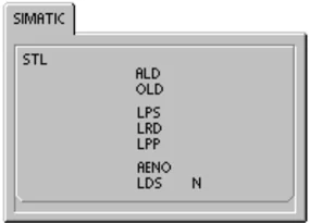
The AND Load instruction (ALD) combines the values in the first and second levels of the stack using a logical AND operation. The result is loaded in the top of stack. After the ALD is executed, the stack depth is decreased by one.
OR Load
The OR Load instruction (OLD) combines the values in the first and second levels of the stack, using a logical OR operation. The result is loaded in the top of the stack. After the OLD is executed, the stack depth is decreased by one.
Logic Push
The Logic Push instruction (LPS) duplicates the top value on the stack and pushes this value onto the stack. The bottom of the stack is pushed off and lost.
Logic Read
The Logic Read instruction (LRD) copies the second stack value to the top of stack. The stack is not pushed or popped, but the old top-of-stack value is destroyed by the copy.
Logic Pop
The Logic Pop instruction (LPP) pops one value off of the stack. The second stack value becomes the new top of stack value.
AND ENO
The AND ENO instruction (AENO) performs a logical AND of the ENO bit with the top of the stack to generate the same effect as the ENO bit of a box in LAD or FBD. The result of the AND operation is the new top of stack.
ENO is a Boolean output for boxes in LAD and FBD. If a box has power flow at the EN input and is executed without error, the ENO output passes power flow to the next element. You can use the ENO as an enable bit that indicates the successful completion of an instruction. The ENO bit is used with the top of stack to affect power flow for execution of subsequent instructions. STL instructions do not have an EN input. The top of the stack must be a logic 1 for conditional instructions to be executed. In STL there is also no ENO output. However, the STL instructions that correspond to LAD and FBD instructions with ENO outputs set a special ENO bit. This bit is accessible with the AENO instruction.
Load Stack
The Load Stack instruction (LDS) duplicates the stack bit (N) on the stack and places this value on top of the stack. The bottom of the stack is pushed off and lost.
Table 6-5 Valid Operands for the Load Stack Instruction \begin{tabular}{lll} \hline Inputs/Outputs & Data Type & Operands \ \hline N & BYTE & Constant (0 to 8) \ \hline \end{tabular}
As shown in Figure 6-3, the S7-200 uses a logic stack to resolve the control logic. In these examples, "iv0" to "iv7" identify the initial values of the logic stack, "nv" identifies a new value provided by the instruction, and "S0" identifies the calculated value that is stored in the logic stack.
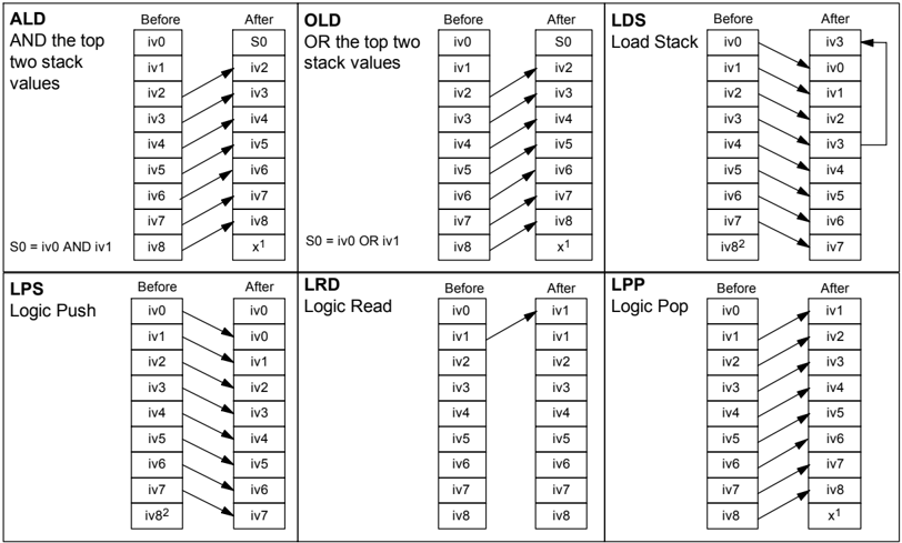
$^{1}$ The value is unknown (it could be either a 0 or a 1). $^{2}$ After the execution of a Logic Push or a Load Stack instruction, value iv8 is lost.
Figure 6-3 Operations of the Logic Stack Instructions
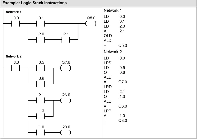
Example: Logic Stack Instructions
76
S7-200 Instruction Set Chapter 6
Set and Reset Dominant Bistable Instructions
The Set Dominant Bistable is a latch where the set dominates. If the set (S1) and reset (R) signals are both true, the output (OUT) is true.
The Reset Dominant Bistable is a latch where the reset dominates. If the set (S) and reset (R1) signals are both true, the output (OUT) is false.
The Bit parameter specifies the Boolean parameter that is set or reset. The optional output reflects the signal state of the Bit parameter.
Table 6-7 shows the truth tables for the sample program.
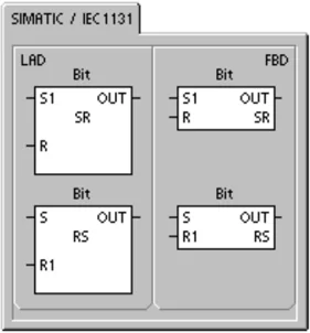
Table 6-6 Valid Operands for the Set Dominant Bistable and Reset Dominant Bistable Instructions \begin{tabular}{|l|l|l|} \hline Inputs/Outputs & Data Types & Operands \ \hline S1, R & BOOL & I, Q, V, M, SM, S, T, C, Power Flow \ \hline S, R1, OUT & BOOL & I, Q, V, M, SM, S, T, C, L, Power Flow \ \hline Bit & BOOL & I, Q, V, M, S \ \hline \end{tabular}
Example: Set and Reset Dominant Bistable Instructions
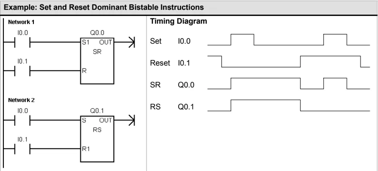
Table 6-7 Truth Table for the Set and Reset Dominant Bistable Instructions \begin{tabular}{|l|c|c|l|} \hline Instruction & S1 & R & Out (Bit) \ \hline Set Dominant Bistable instruction (SR) & 0 & 0 & Previous state \ \cline{2-4} & 0 & 1 & 0 \ \cline{2-4} & 1 & 0 & 1 \ \cline{2-4} & 1 & 1 & 1 \ \hline Instruction & S & R1 & Out (Bit) \ \hline Reset Dominant Bistable instruction (RS) & 0 & 0 & Previous state \ \cline{2-4} & 0 & 1 & 0 \ \cline{2-4} & 1 & 0 & 1 \ \cline{2-4} & 1 & 1 & 0 \ \hline \end{tabular}
77
Clock Instructions
Read Real-Time Clock and Set Real-Time Clock
The Read Real-Time Clock (TODR) instruction reads the current time and date from the hardware clock and loads it in an 8-byte Time buffer starting at address T. The Set Real-Time Clock (TODW) instruction writes the current time and date to the hardware clock, beginning at the 8-byte Time buffer address specified by T.
You must code all date and time values in BCD format (for example, 16#97 for the year 1997). Figure 6-4 shows the format of the 8-Byte Time buffer (T).
The time-of-day (TOD) clock initializes the following date and time after extended power outages or when memory has been lost:
Date: 01-Jan-90 Time: 00:00:00 Day of Week: Sunday
Error conditions that set ENO = 0 ■ 0006 (indirect address) ■ 0007 (TOD data error) Set Real-Time Clock only ■ 000C (clock not present)
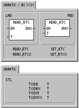
Table 6-8 Valid Operands for the Clock Instructions \begin{tabular}{|l|l|l|} \hline Inputs/Outputs & Data Types & Operands \ \hline T & BYTE & IB, QB, VB, MB, SMB, SB, LB, *VD, *LD, *AC \ \hline \end{tabular}
Figure 6-4 Format of the 8-Byte Time Buffer (T)

S7-200 Instruction Set Chapter 6

Tip The S7-200 CPU does not perform a check to verify that the day of week is correct based upon the date. Invalid dates, such as February 30, could be accepted. You should ensure that the date you enter is correct.
Do not use the TODR/TODW instruction in both the main program and in an interrupt routine. A TODR/TODW instruction in an interrupt routine that attempts to execute while another TODR/TODW instruction is in process cannot be executed. SM4.3 is set indicating that two simultaneous accesses to the clock were attempted (non-fatal error 0007).
The time-of-day clock in the S7-200 uses only the least significant two digits for the year, so for the year 2000, the year is represented as 00. The S7-200 PLC does not use the year information in any way. However, user programs that use arithmetic or compares with the year’s value must take into account the two-digit representation and the change in century.
Leap year is correctly handled through year 2096.
Read Real Time Clock Extended
The Read Real Time Clock Extended (TODRX) instruction reads the current time, date, and daylight savings configuration from the PLC and loads it in a 19-byte buffer beginning at the address specified by T.
Set Real Time Clock Extended
The Set Real Time Clock (TODWX) instruction writes the current time, date, and daylight savings configuration to the PLC beginning at the 19-byte buffer address specified by T.
You must code all date and time values in BCD format (for example, 16#02 for the year 2002). Table 6-9 shows the format of the 19-Byte Time Buffer (T).
The time-of-day clock initializes the following date and time after extended power outages or memory has been lost:
Date: 01-Jan-90 Time 00:00:00 Day of Week: Sunday
Error conditions that set ENO = 0
- 0006 (indirect address)
- 000C (clock cartridge not present)
- 0091 (range error)
Error conditions that set ENO = 0
- 0006 (indirect address)
- 0007 (TOD data error)
- 000C (clock cartridge not present)
- 0091 (range error)
Tip The only time the S7-200 CPU uses bytes 9 to 18 is when the “User Specified” mode is selected in byte 8. Otherwise, the last value written to these bytes by STEP 7-Micro/WIN or the SET_RTCX instruction is returned.
79
Table 6-9 Format of the 19-Byte Time Buffer (TI)
| T Byte | Description | Byte Data |
|---|---|---|
| 0 | year (0–99) | current year (BCD value) |
| 1 | month (1–12) | current month (BCD value) |
| 2 | day (1–31) | current day (BCD value) |
| 3 | hour (0–23) | current hour (BCD value) |
| 4 | minute (0–59) | current minute (BCD value) |
| 5 | second (0–59) | current second (BCD value) |
| 6 | 00 | reserved – always set to 00 |
| 7 | day of week (1–7) | current day of the week, 1=Sunday (BCD value) |
| 8 | mode (00H–03H, 08H, 10H–13H, FFH) | correction mode:00H = correction disabled01H = EU (time zone offset from UTC = 0 hrs)¹02H = EU (time zone offset from UTC = +1 hrs)¹03H = EU (time zone offset from UTC = +2 hrs)¹04H–07H = reserved08H = EU (time zone offset from UTC = –1 hrs)¹09H–0FH = reserved10H = US²11H = Australia³12H = Australia (Tasmania)⁴13H = New Zealand⁵14H–FEH = reservedFFH = user specified (using values in bytes 9–18) |
| 9 | correction hours (0–23) | correction amount, hours (BCD value) |
| 10 | correction minutes (0–59) | correction amount, minutes (BCD value) |
| 11 | beginning month (1–12) | beginning month of daylight saving time (BCD value) |
| 12 | beginning day (1–31) | beginning day of daylight saving time (BCD value) |
| 13 | beginning hour (0–23) | beginning hour of daylight saving time (BCD value) |
| 14 | beginning minute (0–59) | beginning minute of daylight saving time (BCD value) |
| 15 | ending month (1–12) | ending month of daylight saving time (BCD value) |
| 16 | ending day (1–31) | ending day of daylight saving time (BCD value) |
| 17 | ending hour (0–23) | ending hour of daylight saving time (BCD value) |
| 18 | ending minute (0–59) | ending minute of daylight saving time (BCD value) |
¹ EU convention: Adjust time ahead one hour on last Sunday in March at 1:00 a.m. UTC. Adjust time back one hour on last Sunday in October at 2:00 a.m UTC. (The local time when the correction is made depends upon the time zone offset from UTC).
² US convention: Adjust time ahead one hour on first Sunday in April at 2:00 a.m local time. Adjust time back one hour on last Sunday in October at 2:00 a.m local time.
³ Australia convention: Adjust time ahead one hour on last Sunday in October at 2:00 a.m. local time. Adjust time back one hour on last Sunday in March at 3:00 a.m. local time.
⁴ Australia (Tasmania) convention: Adjust time ahead one hour on first Sunday in October at 2:00 a.m. local time. Adjust time back one hour on last Sunday in March at 3:00 a.m. local time
⁵ New Zealand convention: Adjust time ahead one hour on first Sunday in October at 2:00 a.m. local time. Adjust time back one hour on first Sunday on or after March 15 at 3:00 a.m. local time
Communications Instructions
Network Read and Network Write Instructions
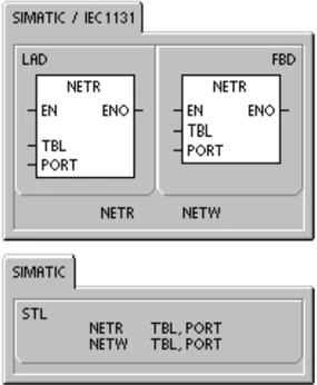
The Network Read instruction (NETR) initiates a communications operation to gather data from a remote device through the specified port (PORT), as defined by the table (TBL). The Network Write instruction (NETW) initiates a communications operation to write data to a remote device through the specified port (PORT), as defined by the table (TBL).
Error conditions that set ENO = 0:
- 0006 (indirect address)
- If the function returns an error and sets the E bit of table status byte (see Figure 6-5)
The Network Read instruction can read up to 16 bytes of information from a remote station, and the Network Write instruction can write up to 16 bytes of information to a remote station.
You can have any number of Network Read and Network Write instructions in the program, but only a maximum of eight Network Read and Network Write instructions can be activated at any one time. For example, you can have 4 Network Read and 4 Network Write instructions, or 2 Network Read and 6 Network Write instructions, active at the same time in a given S7-200.
You can use the Network Read/Network Write Instruction Wizard to configure the counter. To start the Network Read/Network Write Instruction Wizard, select the Tools > Instruction Wizard menu command and then select Network Read/Network Write from the Instruction Wizard window.
Table 6-10 Valid Operands for the Network Read and Network Write Instructions
Figure 6-5 describes the table that is referenced by the TBL parameter, and Table 6-11 lists the error codes.
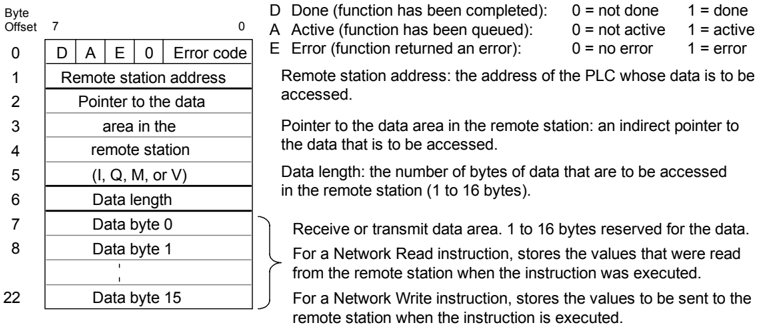
Figure 6-5 TBL Parameter for the Network Read and Network Write Instructions
Table 6-11 Error Codes for the TBL Parameter
| Code | Definition |
|---|---|
| 0 | No error. |
| 1 | Time-out error: Remote station not responding. |
| 2 | Receive error: Parity, framing, or checksum error in the response. |
| 3 | Offline error: Collisions caused by duplicate station addresses or failed hardware. |
| 4 | Queue overflow error: More than 8 Network Read or Network Write instructions have been activated. |
| 5 | Protocol violation: Attempt to execute a Network Read or Network Write instruction without enabling the PPI Master Mode in SMB30 or SMB130. |
| 6 | Illegal parameter: TBL parameter contains an illegal or invalid value. |
| 7 | No resource: Remote station is busy. (An upload or a download sequence is in process.) |
| 8 | Layer 7 error: Application protocol violation |
| 9 | Message error: Wrong data address or incorrect data length |
| A to F | Not used. (Reserved) |
Figure 6-6 shows an example to illustrate the utility of the Network Read and Network Write instructions. For this example, consider a production line where tubs of butter are being filled and sent to one of four boxing machines (case packers). The case packer packs eight tubs of butter into a single cardboard box. A diverter machine controls the flow of butter tubs to each of the case packers. Four S7-200s control the case packers, and an S7-200 with a TD 200 operator interface controls the diverter.
82
S7-200 Instruction Set Chapter 6
 t Out of butter tubs to pack; t=1, out of butter tubs
b Box supply is low; b=1, must add boxes in the next 30 minutes
g Glue supply is low; g=1, must add glue in the next 30 minutes
eee error code identifying the type of fault experienced
f Fault indicator; f=1, the case packer has detected an error
Figure 6-6 Example of the Network Read and Network Write Instructions
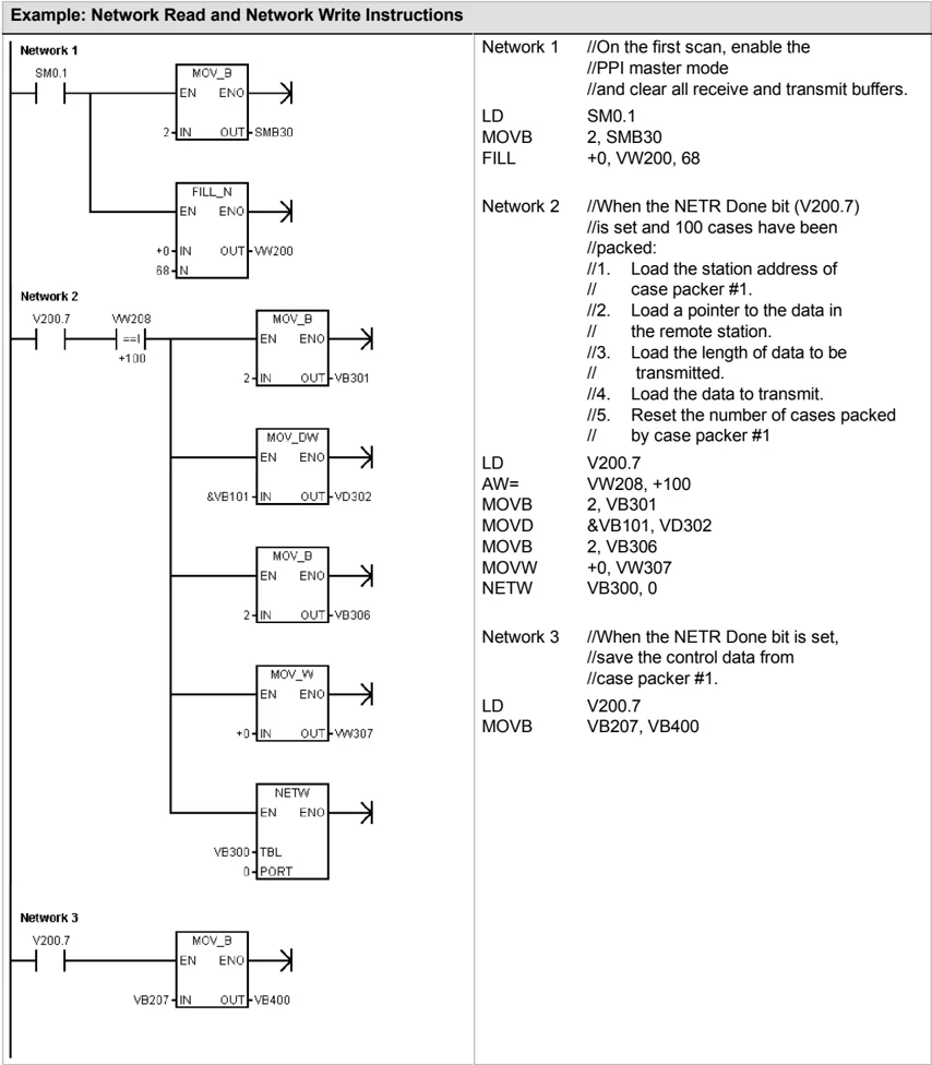
Figure 6-7 shows the receive buffer (VB200) and transmit buffer (VB300) for accessing the data in station 2. The S7-200 uses a Network Read instruction to read the control and status information on a continuous basis from each of the case packers. Each time a case packer has packed 100 cases, the diverter notes this and sends a message to clear the status word using a Network Write instruction.
Receive Buffer for reading from Case Packer #1
Transmit Buffer for clearing the count of Case Packer #1
Figure 6-7 Sample TBL Data for the Network Read/Write Example
83
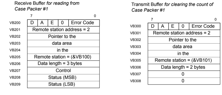
Example: Network Read and Network Write Instructions
Network 1 //On the first scan, enable the //PPI master mode //and clear all receive and transmit buffers. LD SM0.1 MOVB 2, SMB30 FILL +0, VW200, 68
Network 2 //When the NETR Done bit (V200.7) //is set and 100 cases have been //packed: //1. Load the station address of // case packer #1. //2. Load a pointer to the data in // the remote station. //3. Load the length of data to be // transmitted. //4. Load the data to transmit. //5. Reset the number of cases packed // by case packer #1 LD V200.7 AW= VW208, +100 MOVB 2, VB301 MOVD &VB101, VD302 MOVB 2, VB306 MOVW +0, VW307 NETW VB300, 0
Network 3 //When the NETR Done bit is set, //save the control data from //case packer #1. LD V200.7 MOVB VB207, VB400
84
S7-200 Instruction Set Chapter 6
Example: Network Read and Network Write Instructions, continued
 Network 4
SM0.1 Y200.6 V200.5
/ / /
MOV_B
EN ENO
2 IN OUT VB201
MOV_DW
EN ENO
&VB100 IN OUT VD202
MOV_B
EN ENO
3 IN OUT VB206
NETR
EN ENO
VB200 TBL
0 PORT
Network 4 //If not the first scan and there are //no errors: //1. Load the station address of // case packer #1. //2. Load a pointer to the data in // the remote station. //3. Load the length of data to // be received. //4. Read the control and status data // in case packer #1.
LDN SM0.1 AN V200.6 AN V200.5 MOVB 2, VB201 MOVD &VB100, VD202 MOVB 3, VB206 NE TR VB200, 0
85
Transmit and Receive Instructions (Freeport)
The Transmit instruction (XMT) is used in Freeport mode to transmit data by means of the communications port(s).
The Receive instruction (RCV) initiates or terminates the receive message function. You must specify a start and an end condition for the Receive box to operate. Messages received through the specified port (PORT) are stored in the data buffer (TBL). The first entry in the data buffer specifies the number of bytes received.
Error conditions that set ENO = 0
- 0006 (indirect address)
- 0009 (simultaneous Transmit/Receive on port 0)
- 000B (simultaneous Transmit/Receive on port 1)
- Receive parameter error sets SM86.6 or SM186.6
- S7-200 CPU is not in Freeport mode
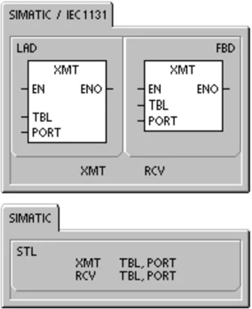
Table 6-12 Valid Operands for the Transmit and Receive Instructions
| Inputs/Outputs | Data Type | Operands |
|---|---|---|
| TBL | BYTE | IB, QB, VB, MB, SMB, SB, *VD, *LD, *AC |
| PORT | BYTE | Constant for CPU 221, CPU 222, CPU 224: 0 for CPU 224XP, CPU 226: 0 or 1 |
For more information about using Freeport mode, see the section Creating User-Defined Protocols with Freeport Mode on page 226 in Chapter 7.
Using Freeport Mode to Control the Serial Communications Port
You can select the Freeport mode to control the serial communications port of the S7-200 by means of the user program. When you select Freeport mode, your program controls the operation of the communications port through the use of the receive interrupts, the transmit interrupts, the Transmit instruction, and the Receive instruction. The communications protocol is entirely controlled by the ladder program while in Freeport mode. SMB30 (for port 0) and SMB130 (for port 1 if your S7-200 has two ports) are used to select the baud rate and parity.
The Freeport mode is disabled and normal communications are re-established (for example, programming device access) when the S7-200 is in STOP mode.
In the simplest case, you can send a message to a printer or a display using only the Transmit (XMT) instruction. Other examples include a connection to a bar code reader, a weighing scale, and a welder. In each case, you must write your program to support the protocol that is used by the device with which the S7-200 communicates while in Freeport mode.
Freeport communications are possible only when the S7-200 is in RUN mode. Enable the Freeport mode by setting a value of 01 in the protocol select field of SMB30 (Port 0) or SMB130 (Port 1). While in Freeport mode, communications with the programming device are not possible.
Tip Freeport mode can be controlled using special memory bit SM0.7, which reflects the current position of the operating mode switch. When SM0.7 is equal to 0, the switch is in TERM position; when SM0.7 = 1, the operating mode switch is in RUN position. If you enable Freeport mode only when the switch is in RUN position, you can use the programming device to monitor or control the S7-200 operation by changing the switch to any other position.