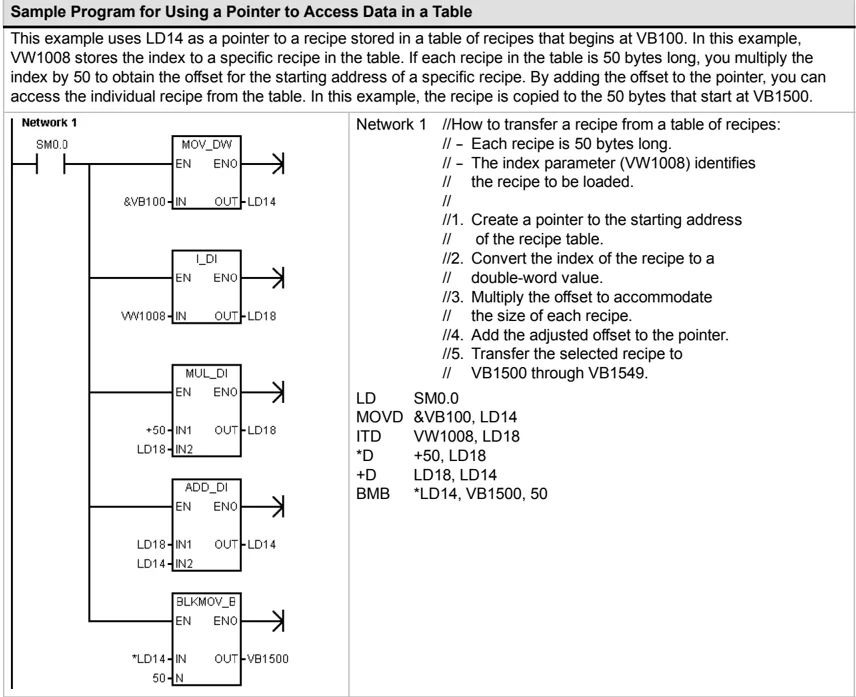
Entering Network 1: Starting the Timer
When M0.0 is off (0), this contact turns on and provides power flow to start the timer. To enter the contact for M0.0:
- Either double-click the Bit Logic icon or click on the plus sign (+) to display the bit logic instructions.
- Select the Normally Closed contact.
- Hold down the left mouse button and drag the contact onto the first network.
- Click on the "???" above the contact and enter the following address: M0.0
- Press the Return key to enter the address for the contact.
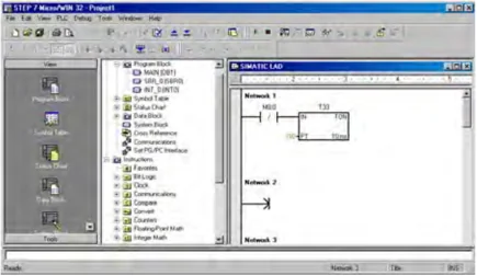
Figure 2-7 Network 1
To enter the timer instruction for T33:
- Double-click the Timers icon to display the timer instructions.
- Select the TON (On-Delay Timer).
- Hold down the left mouse button and drag the timer onto the first network.
- Click on the "???" above the timer box and enter the following timer number: T33
- Press the Return key to enter the timer number and to move the focus to the preset time (PT) parameter.
- Enter the following value for the preset time: 100
- Press the Return key to enter the value.
Entering Network 2: Turning the Output On
When the timer value for T33 is greater than or equal to 40 (40 times 10 milliseconds, or 0.4 seconds), the contact provides power flow to turn on output Q0.0 of the S7-200. To enter the Compare instruction:
- Double-click the Compare icon to display the compare instructions. Select the >=I instruction (Greater-Than-Or-Equal-To-Integer).
- Hold down the left mouse button and drag the compare instruction onto the second network.
- Click on the "???" above the contact and enter the address for the timer value: T33
- Press the Return key to enter the timer number and to move the focus to the other value to be compared with the timer value.
- Enter the following value to be compared with the timer value: 40
- Press the Return key to enter the value.
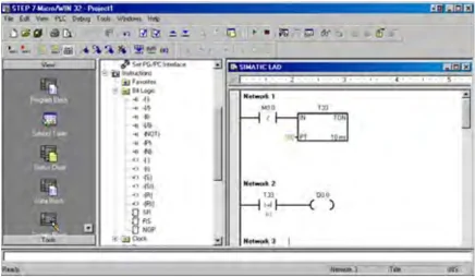
Figure 2-8 Network 2
To enter the instruction for turning on output Q0.0:
- Double-click the Bit Logic icon to display the bit logic instructions and select the output coil.
- Hold down the left mouse button and drag the coil onto the second network.
- Click on the "???" above the coil and enter the following address: Q0.0
- Press the Return key to enter the address for the coil.
Getting Started Chapter 2
Entering Network 3: Resetting the Timer
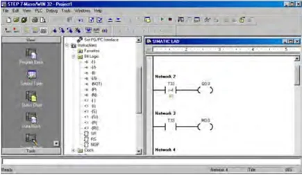
When the timer reaches the preset value (100) and turns the timer bit on, the contact for T33 turns on. Power flow from this contact turns on the M0.0 memory location. Because the timer is enabled by a Normally Closed contact for M0.0, changing the state of M0.0 from off (0) to on (1) resets the timer.
To enter the contact for the timer bit of T33:
- Select the Normally Open contact from the bit logic instructions.
- Hold down the left mouse button and drag the contact onto the third network.
- Click on the "???" above the contact and enter the address of the timer bit: T33
- Press the Return key to enter the address for the contact.
!
Figure 2-9 Network 3
To enter the coil for turning on M0.0:
- Select the output coil from the bit logic instructions.
- Hold down the left mouse button and drag the output coil onto the third network.
- Double-click the "???" above the coil and enter the following address: M0.0
- Press the Return key to enter the address for the coil.
Saving the Sample Project
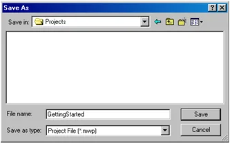
After entering the three networks of instructions, you have finished entering the program. When you save the program, you create a project that includes the S7-200 CPU type and other parameters. To save the project:
- Select the File > Save As menu command from the menu bar.
- Enter a name for the project in the Save As dialog box.
- Click OK to save the project.
After saving the project, you can download the program to the S7-200.
!
Figure 2-10 Saving the Example Program
Downloading the Sample Program
Tip
Each STEP 7-Micro/WIN project is associated with a CPU type (CPU 221, CPU 222, CPU 224, CPU 224XP, or CPU 226). If the project type does not match the CPU to which you are connected, STEP 7-Micro/WIN indicates a mismatch and prompts you to take an action. If this occurs, choose “Continue Download” for this example.
- Click the Download icon on the toolbar or select the File > Download menu command to download the program. See Figure 2-11.
- Click OK to download the elements of the program to the S7-200.
If your S7-200 is in RUN mode, a dialog box prompts you to place the S7-200 in STOP mode. Click Yes to place the S7-200 into STOP mode.
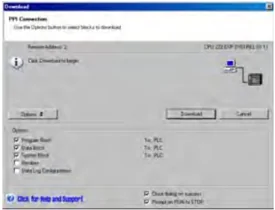
Figure 2-11 Downloading the Program
Placing the S7-200 in RUN Mode
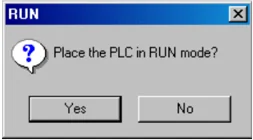
For STEP 7-Micro/WIN to place the S7-200 CPU in RUN mode, the mode switch of the S7-200 must be set to TERM or RUN. When you place the S7-200 in RUN mode, the S7-200 executes the program:
- Click the RUN icon on the toolbar or select the PLC > RUN menu command.
- Click OK to change the operating mode of the S7-200.
When the S7-200 goes to RUN mode, the output LED for Q0.0 turns on and off as the S7-200 executes the program.

Figure 2-12 Placing the S7-200 in RUN Mode
Congratulations! You have just completed your first S7-200 program.
You can monitor the program by selecting the Debug > Program Status menu command. STEP 7-Micro/WIN displays the values for the instructions. To stop the program, place the S7-200 in STOP mode by clicking the STOP icon or by selecting the PLC > STOP menu command.
Installing the S7-200
The S7-200 equipment is designed to be easy to install. You can use the mounting holes to attach the modules to a panel, or you can use the built-in clips to mount the modules onto a standard (DIN) rail. The small size of the S7-200 allows you to make efficient use of space.
This chapter provides guidelines for installing and wiring your S7-200 system.
I n This C hapter
-
Guidelines for Installing S7-200 Devices . . . . . . . . . . . . . . . . . . . . . . . . . . . . . . . . . . . . . . . . . . . . . . . . . . . . . . . . . . . . . . . . . . . . . . . . . . . . . . . . . . . . . . . . . . . . . . . . . . . . . . . . . . . . . . . . . . . . . . . . ........ 16
-
Installing and Removing the S7-200 Modules . . . . . . . . . . . . . . . . . . . . . . . . . . . . . . . . . . . . . . . . . . . . . . . . . . . . . . . . . . . . . . . . . . . . . . . . . . . . . . . . . . . . . . . . . . . . . . . . . . . . . . . . ........ 17
-
Guidelines for Grounding and Wiring . . . . . . . . . . . . . . . . . . . . . . . . . . . . . . . . . . . . . . . . . . . . . . . . . . . . . . . . . . . . . . . . . . . . . . . . . . . . . . . . . . . . . . . . . . . . . . . . . . . . . ........

Guidelines for Installing S7-200 Devices
You can install an S7-200 either on a panel or on a standard rail, and you can orient the S7-200 either horizontally or vertically.
Warning The SIMATIC S7-200 PLCs are Open Type Controllers. It is required that you install the S7-200 in a housing, cabinet, or electric control room. Entry to the housing, cabinet, or electric control room should be limited to authorized personnel.
Failure to follow these installation requirements could result in death or serious injury to personnel, and/or damage to equipment.
Always follow these requirements when installing S7-200 PLCs.
Separate the S7-200 Devices from Heat, High Voltage, and Electrical Noise
As a general rule for laying out the devices of your system, always separate the devices that generate high voltage and high electrical noise from the low-voltage, logic-type devices such as the S7-200.
When configuring the layout of the S7-200 inside your panel, consider the heat-generating devices and locate the electronic-type devices in the cooler areas of your cabinet. Operating any electronic device in a high-temperature environment will reduce the time to failure.
Consider also the routing of the wiring for the devices in the panel. Avoid placing low voltage signal wires and communications cables in the same tray with AC power wiring and high-energy, rapidly-switched DC wiring.
Provide Adequate Clearance for Cooling and Wiring
S7-200 devices are designed for natural convection cooling. For proper cooling, you must provide a clearance of at least 25 mm above and below the devices. Also, allow at least 75 mm of depth.
Caution For vertical mounting, the maximum allowable ambient temperature is reduced by 10 degrees C. Mount the S7-200 CPU below any expansion modules.
When planning your layout for the S7-200 system, allow enough clearance for the wiring and communications cable connections. For additional flexibility in configuring the layout of the S7-200 system, use the I/O expansion cable.
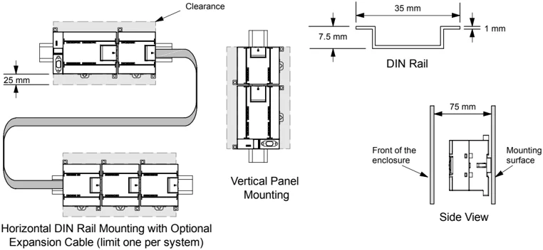
Figure 3-1 Mounting Methods, Orientation, and Clearance
16
Power Budget
All S7-200 CPUs have an internal power supply that provides power for the CPU, the expansion modules, and other 24 VDC user power requirements.
The S7-200 CPU provides the 5 VDC logic power needed for any expansion in your system. Pay careful attention to your system configuration to ensure that your CPU can supply the 5V power required by your selected expansion modules. If your configuration requires more power than the CPU can supply, you must remove a module or select a CPU with more power capability. Refer to Appendix A for information about the 5 VDC logic budget supplied by your S7-200 CPU and the 5 VDC power requirements of the expansion modules. Use Appendix B as a guide for determining how much power (or current) the CPU can provide for your configuration.
All S7-200 CPUs also provide a 24 VDC sensor supply that can supply 24 VDC for input points, for relay coil power on the expansion modules, or for other requirements. If your power requirements exceed the budget of the sensor supply, then you must add an external 24 VDC power supply to your system. Refer to Appendix A for the 24 VDC sensor supply power budget for your particular S7-200 CPU.
If you require an external 24 VDC power supply, ensure that the power supply is not connected in parallel with the sensor supply of the S7-200 CPU. For improved electrical noise protection, it is recommended that the commons (M) of the different power supplies be connected.
Warning Connecting an external 24 VDC power supply in parallel with the S7-200 24 VDC sensor supply can result in a conflict between the two supplies as each seeks to establish its own preferred output voltage level. The result of this conflict can be shortened lifetime or immediate failure of one or both power supplies, with consequent unpredictable operation of the PLC system. Unpredictable operation could result in death or serious injury to personnel, and/or damage to equipment. The S7-200 DC sensor supply and any external power supply should provide power to different points.
Installing and Removing the S7-200 Modules
The S7-200 can be easily installed on a standard DIN rail or on a panel.
Prerequisites
Before you install or remove any electrical device, ensure that the power to that equipment has been turned off. Also, ensure that the power to any related equipment has been turned off.
Warning Attempts to install or remove S7-200 or related equipment with the power applied could cause electric shock or faulty operation of equipment. Failure to disable all power to the S7-200 and related equipment during installation or removal procedures could result in death or serious injury to personnel, and/or damage to equipment. Always follow appropriate safety precautions and ensure that power to the S7-200 is disabled before attempting to install or remove S7-200 CPUs or related equipment.
Always ensure that whenever you replace or install an S7-200 device you use the correct module or equivalent device.
Warning If you install an incorrect module, the program in the S7-200 could function unpredictably. Failure to replace an S7-200 device with the same model, orientation, or order could result in death or serious injury to personnel, and/or damage to equipment. Replace an S7-200 device with the same model, and be sure to orient and position it correctly.
Mounting Dimensions
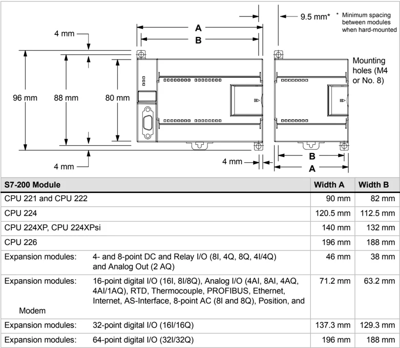
The S7-200 CPUs and expansion modules include mounting holes to facilitate installation on panels. Refer to Table 3-1 for the mounting dimensions.
Table 3-1 Mounting Dimensions
| S7-200 Module | Width A | Width B |
|---|---|---|
| CPU 221 and CPU 222 | 90 mm | 82 mm |
| CPU 224 | 120.5 mm | 112.5 mm |
| CPU 224XP, CPU 224XPsi | 140 mm | 132 mm |
| CPU 226 | 196 mm | 188 mm |
| Expansion modules: 4- and 8-point DC and Relay I/O (8I, 4Q, 8Q, 4I/4Q) and Analog Out (2 AQ) | 46 mm | 38 mm |
| Expansion modules: 16-point digital I/O (16I, 8I/8Q), Analog I/O (4AI, 8AI, 4AQ, 4AI/1AQ), RTD, Thermocouple, PROFIBUS, Ethernet, Internet, AS-Interface, 8-point AC (8I and 8Q), Position, and Modem | 71.2 mm | 63.2 mm |
| Expansion modules: 32-point digital I/O (16I/16Q) | 137.3 mm | 129.3 mm |
| Expansion modules: 64-point digital I/O (32I/32Q) | 196 mm | 188 mm |
Installing a CPU or Expansion Module
Installing the S7-200 is easy! Just follow these steps.
Panel Mounting
- Locate, drill, and tap the mounting holes (M4 or American Standard number 8), using the dimensions in Table 3-1.
- Secure the module(s) to the panel, using the appropriate screws.
- If you are using an expansion module, connect the expansion module ribbon cable into the expansion port connector under the access door.
DIN Rail Mounting
- Secure the rail to the mounting panel every 75 mm.
- Snap open the DIN clip (located on the bottom of the module) and hook the back of the module onto the DIN rail.
- If you are using an expansion module, connect the expansion module ribbon cable into the expansion port connector under the access door.
- Rotate the module down to the DIN rail and snap the clip closed. Carefully check that the clip has fastened the module securely onto the rail. To avoid damage to the module, press on the tab of the mounting hole instead of pressing directly on the front of the module.
18
Installing the S7-200 Chapter 3
Tip Using DIN rail stops could be helpful if your S7-200 is in an environment with high vibration potential or if the S7-200 has been installed vertically. If your system is in a high-vibration environment, then panel-mounting the S7-200 will provide a greater level of vibration protection.
Removing a CPU or Expansion Module
To remove an S7-200 CPU or expansion module, follow these steps:
- Remove power from the S7-200.
- Disconnect all the wiring and cabling that is attached to the module. Most S7-200 CPU and expansion modules have removable connectors to make this job easier.
- If you have expansion modules connected to the unit that you are removing, open the access cover door and disconnect the expansion module ribbon cable from the adjacent modules.
- Unscrew the mounting screws or snap open the DIN clip.
- Remove the module.
Removing and Reinstalling the Terminal Block Connector
Most S7-200 modules have removable connectors to make installing and replacing the module easy. Refer to Appendix A to determine whether your S7-200 module has removable connectors. You can order an optional fan-out connector for modules that do not have removable connectors. See Appendix E for order numbers.
To Remove the Connector
- Open the connector door to gain access to the connector.
- Insert a small screwdriver in the notch in the middle of the connector.
- Remove the terminal connector by prying the screwdriver away from the S7-200 housing. See Figure 3-2.
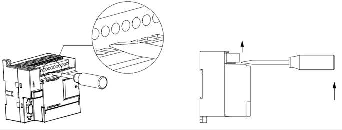
Figure 3-2 Removing the Connector
To Reinstall the Connector
- Open the connector door.
- Align the connector with the pins on the unit and align the wiring edge of the connector inside the rim of the connector base.
- Press down firmly to rotate the connector until it snaps into place. Check carefully to ensure that the connector is properly aligned and fully engaged.
19
Guidelines for Grounding and Wiring
Proper grounding and wiring of all electrical equipment is important to help ensure the optimum operation of your system and to provide additional electrical noise protection for your application and the S7-200.
Prerequisites
Before you ground or install wiring to any electrical device, ensure that the power to that equipment has been turned off. Also, ensure that the power to any related equipment has been turned off.
Ensure that you follow all applicable electrical codes when wiring the S7-200 and related equipment. Install and operate all equipment according to all applicable national and local standards. Contact your local authorities to determine which codes and standards apply to your specific case.

Warning
Attempts to install or wire the S7-200 or related equipment with power applied could cause electric shock or faulty operation of equipment. Failure to disable all power to the S7-200 and related equipment during installation or removal procedures could result in death or serious injury to personnel, and/or damage to equipment.
Always follow appropriate safety precautions and ensure that power to the S7-200 is disabled before attempting to install or remove the S7-200 or related equipment.
Always take safety into consideration as you design the grounding and wiring of your S7-200 system. Electronic control devices, such as the S7-200, can fail and can cause unexpected operation of the equipment that is being controlled or monitored. For this reason, you should implement safeguards that are independent of the S7-200 to protect against possible personal injury or equipment damage.
Warning
Control devices can fail in an unsafe condition, resulting in unexpected operation of controlled equipment. Such unexpected operations could result in death or serious injury to personnel, and/or damage to equipment.
Use an emergency stop function, electromechanical overrides, or other redundant safeguards that are independent of the S7-200.
Guidelines for Isolation
S7-200 AC power supply boundaries and I/O boundaries to AC circuits have been designed and approved to provide safe separation between AC line voltages and low voltage circuits. These boundaries include double or reinforced insulation, or basic plus supplementary insulation, according to various standards. Components which cross these boundaries such as optical couplers, capacitors, transformers, and relays have been approved as providing safe separation. Isolation boundaries which meet these requirements have been identified in S7-200 product data sheets as having 1500VAC or greater isolation. This designation is based on a routine factory test of (2Ue + 1000VAC) or equivalent according to approved methods. S7-200 safe separation boundaries have been type tested to 4242 VDC.
The sensor supply output, communications circuits, and internal logic circuits of an S7-200 with included AC power supply are sourced as SELV (safety extra-low voltage) according to EN 61131-2. These circuits become PELV (protective extra-low voltage) if the sensor supply M, or any other non-isolated M connection to the S7-200 is connected to ground. Other S7-200 M connections which may ground reference the low voltage are designated as not isolated to logic on specific product data sheets. Examples are RS485 communications port M, analog I/O M, and relay coil power M.
To maintain the SELV / PELV character of the S7-200 low voltage circuits, external connections to communications ports, analog circuits, and all 24V nominal power supply and I/O circuits must be powered from approved sources that meet the requirements of SELV, PELV, Class 2, Limited Voltage, or Limited Power according to various standards.
Installing the S7-200 Chapter 3
Warning Use of non-isolated or single insulation supplies to supply low voltage circuits from an AC line can result in hazardous voltages appearing on circuits that are expected to be touch safe, such as communications circuits and low voltage sensor wiring. Such unexpected high voltages could result in death or serious injury to personnel, and/or damage to equipment. Only use high voltage to low voltage power converters that are approved as sources of touch safe, limited voltage circuits.
Guidelines for Grounding the S7-200
The best way to ground your application is to ensure that all the common and ground connections of your S7-200 and related equipment are grounded to a single point. This single point should be connected directly to the earth ground for your system.
For improved electrical noise protection, it is recommended that all DC common returns be connected to the same single-point earth ground. Connect the 24 VDC sensor supply common (M) to earth ground.
All ground wires should be as short as possible and should use a large wire size, such as 2 mm² (14 AWG).
When locating grounds, remember to consider safety grounding requirements and the proper operation of protective interrupting devices.
Guidelines for Wiring the S7-200
When designing the wiring for your S7-200, provide a single disconnect switch that simultaneously removes power from the S7-200 CPU power supply, from all input circuits, and from all output circuits. Provide overcurrent protection, such as a fuse or circuit breaker, to limit fault currents on supply wiring. You might want to provide additional protection by placing a fuse or other current limit in each output circuit.
Install appropriate surge suppression devices for any wiring that could be subject to lightning surges.
Avoid placing low-voltage signal wires and communications cables in the same wire tray with AC wires and high-energy, rapidly switched DC wires. Always route wires in pairs, with the neutral or common wire paired with the hot or signal-carrying wire.
Use the shortest wire possible and ensure that the wire is sized properly to carry the required current. The connector accepts wire sizes from 2 mm² to 0.3 mm² (14 AWG to 22 AWG). Use shielded wires for optimum protection against electrical noise. Typically, grounding the shield at the S7-200 gives the best results.
When wiring input circuits that are powered by an external power supply, include an overcurrent protection device in that circuit. External protection is not necessary for circuits that are powered by the 24 VDC sensor supply from the S7-200 because the sensor supply is already current-limited.
Most S7-200 modules have removable connectors for user wiring. (Refer to Appendix A to determine if your module has removable connectors.) To prevent loose connections, ensure that the connector is seated securely and that the wire is installed securely into the connector. To avoid damaging the connector, be careful that you do not over-tighten the screws. The maximum torque for the connector screw is 0.56 N-m (5 inch-pounds).
To help prevent unwanted current flows in your installation, the S7-200 provides isolation boundaries at certain points. When you plan the wiring for your system, you should consider these isolation boundaries. Refer to Appendix A for the amount of isolation provided and the location of the isolation boundaries. Isolation boundaries rated less than 1500 VAC must not be depended on as safety boundaries.
Tip For a communications network, the maximum length of the communications cable is 50 m without using a repeater. The communications port on the S7-200 is non-isolated. Refer to Chapter 7 for more information.
21
Guidelines for Inductive Loads
You should equip inductive loads with suppression circuits to limit voltage rise when the control output turns off. Suppression circuits protect your outputs from premature failure due to high inductive switching currents. In addition, suppression circuits limit the electrical noise generated when switching inductive loads.
Tip The effectiveness of a given suppression circuit depends on the application, and you must verify it for your particular use. Always ensure that all components used in your suppression circuit are rated for use in the application.
DC Outputs and Relays That Control DC Loads
The DC outputs have internal protection that is adequate for most applications. Since the relays can be used for either a DC or an AC load, internal protection is not provided.
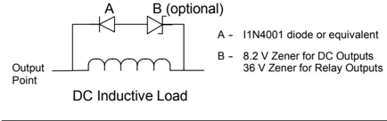
Figure 3-3 shows a sample suppression circuit for a DC load. In most applications, the addition of a diode (A) across the inductive load is suitable, but if your application requires faster turn-off times, then the addition of a Zener diode (B) is recommended. Be sure to size your Zener diode properly for the amount of current in your output circuit.

Figure 3-3 Suppression Circuit for a DC Load
AC Outputs and Relays That Control AC Loads
The AC outputs have internal protection that is adequate for most applications. Since the relays can be used for either a DC or an AC load, internal protection is not provided.
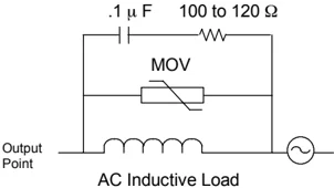
Figure 3-4 shows a sample suppression circuit for an AC load. When you use a relay or AC output to switch 115 V/230 VAC loads, place resistor/capacitor networks across the AC load as shown in this figure. You can also use a metal oxide varistor (MOV) to limit peak voltage. Ensure that the working voltage of the MOV is at least 20% greater than the nominal line voltage.

Figure 3-4 Suppression Circuit for an AC Load
Warning When relay expansion modules are used to switch AC inductive loads, the external resistor/capacitor noise suppression circuit must be placed across the AC load to prevent unexpected machine or process operation. See Figure 3-4.
Guidelines for Lamp Loads
Lamp loads are damaging to relay contacts because of the high turn-on surge current. This surge current will nominally be 10 to 15 times the steady state current for a Tungsten lamp. A replaceable interposing relay or surge limiter is recommended for lamp loads that will be switched a large number of times during the lifetime of the application.
22
PLC Concepts
The basic function of the S7-200 is to monitor field inputs and, based on your control logic, turn on or off field output devices. This chapter explains the concepts used to execute your program, the various types of memory used, and how that memory is retained.
I n This Chapter
- Understanding How the S7-200 Executes Your Control Logic ........ 24
- Accessing the Data of the S7-200 ........ 27
- Understanding How the S7-200 Saves and Restores Data ........ 36
- Selecting the Operating Mode for the S7-200 CPU ........ 40
- Using the S7-200 Explorer ........ 41
- Features of the S7-200 ........ 41
23

Understanding How the S7-200 Executes Your Control Logic
The S7-200 continuously cycles through the control logic in your program, reading and writing data.
The S7-200 Relates Your Program to the Physical Inputs and Outputs
The basic operation of the S7-200 is very simple:
☐ The S7-200 reads the status of the inputs.
☐ The program that is stored in the S7-200 uses these inputs to evaluate the control logic. As the program runs, the S7-200 updates the data.
☐ The S7-200 writes the data to the outputs.
Figure 4-1 shows a simple diagram of how an electrical relay diagram relates to the S7-200. In this example, the state of the switch for starting the motor is combined with the states of other inputs. The calculations of these states then determine the state for the output that goes to the actuator which starts the motor.
 Figure 4-1 Controlling Inputs and Outputs
The S7-200 Executes Its Tasks in a Scan Cycle
The S7-200 executes a series of tasks repetitively. This cyclical execution of tasks is called the scan cycle. As shown in Figure 4-2, the S7-200 performs most or all of the following tasks during a scan cycle:
☐ Reading the inputs: The S7-200 copies the state of the physical inputs to the process-image input register.
☐ Executing the control logic in the program: The S7-200 executes the instructions of the program and stores the values in the various memory areas.
☐ Processing any communications requests: The S7-200 performs any tasks required for communications.
☐ Executing the CPU self-test diagnostics: The S7-200 ensures that the firmware, the program memory, and any expansion modules are working properly.
☐ Writing to the outputs: The values stored in the process-image output register are written to the physical outputs.
 Figure 4-2 S7-200 Scan Cycle
The execution of the user program is dependent upon whether the S7-200 is in STOP mode or in RUN mode. In RUN mode, your program is executed; in STOP mode, your program is not executed.
24
PLC Concepts Chapter 4
Reading the Inputs
Digital inputs: Each scan cycle begins by reading the current value of the digital inputs and then writing these values to the process-image input register.
Analog inputs: The S7-200 does not update analog inputs from expansion modules as part of the normal scan cycle unless filtering of analog inputs is enabled. An analog filter is provided to allow you to have a more stable signal. You can enable the analog filter for each analog input point.
When analog input filtering is enabled for an analog input, the S7-200 updates that analog input once per scan cycle, performs the filtering function, and stores the filtered value internally. The filtered value is then supplied each time your program accesses the analog input.
When analog filtering is not enabled, the S7-200 reads the value of the analog input from expansion modules each time your program accesses the analog input.
Analog inputs AIW0 and AIW2 included on the CPU 224XP are updated every scan with the most recent result from the analog-to-digital converter. This converter is an averaging type (sigma-delta) and those values will usually not need software filtering.
Tip Analog input filtering is provided to allow you to have a more stable analog value. Use the analog input filter for applications where the input signal varies slowly with time. If the signal is a high-speed signal, then you should not enable the analog filter.
Do not use the analog filter with modules that pass digital information or alarm indications in the analog words. Always disable analog filtering for RTD, Thermocouple, and AS-Interface Master modules.
Executing the Program
During the execution phase of the scan cycle, the S7-200 executes your program, starting with the first instruction and proceeding to the end instruction. The immediate I/O instructions give you immediate access to inputs and outputs during the execution of either the program or an interrupt routine.
If you use subroutines in your program, the subroutines are stored as part of the program. The subroutines are executed when they are called by the main program, by another subroutine, or by an interrupt routine. Subroutine nesting depth is 8 from the main and 1 from an interrupt routine.
If you use interrupts in your program, the interrupt routines that are associated with the interrupt events are stored as part of the program. The interrupt routines are not executed as part of the normal scan cycle, but are executed when the interrupt event occurs (which could be at any point in the scan cycle).
Local memory is reserved for each of eleven entities: one main, eight subroutine nesting levels when initiated from the main, one interrupt, and one subroutine nesting level when initiated from an interrupt routine. Local memory has a local scope in that it is available only within its associated program entity, and cannot be accessed by the other program entities. For more information about Local memory, refer to Local Memory Area: L in this chapter.
Figure 4-3 depicts the flow of a typical scan including the Local memory usage and two interrupt events, one during the program-execution phase and another during the communications phase of the scan cycle. Subroutines are called by the next higher level, and are executed when called. Interrupt routines are not called; they are a result of an occurrence of the associated interrupt event.
25
 Figure 4-3 Typical Scan Flow
26
PLC Concepts Chapter 4
Processing Any Communications Requests During the message-processing phase of the scan cycle, the S7-200 processes any messages that were received from the communications port or intelligent I/O modules.
Executing the CPU Self-test Diagnostics During this phase of the scan cycle, the S7-200 checks for proper operation of the CPU and for the status of any expansion modules.
Writing to the Digital Outputs At the end of every scan cycle, the S7-200 writes the values stored in the process-image output register to the digital outputs. (Analog outputs are updated immediately, independently from the scan cycle.)
Accessing the Data of the S7-200
The S7-200 stores information in different memory locations that have unique addresses. You can explicitly identify the memory address that you want to access. This allows your program to have direct access to the information. Table 4-1 shows the range of integer values that can be represented by the different sizes of data.
Table 4-1 Decimal and Hexadecimal Ranges for the Different Sizes of Data
\begin{tabular}{|l|l|l|l|} \hline Representation & Byte (B) & Word (W) & Double Word (D) \ \hline Unsigned Integer & 0 to 255 \newline 0 to FF & 0 to 65,535 \newline 0 to FFFF & 0 to 4,294,967,295 \newline 0 to FFFF FFFF \ \hline Signed Integer & -128 to +127 \newline 80 to 7F & -32,768 to +32,767 \newline 8000 to 7FFF & -2,147,483,648 to +2,147,483,647 \newline 8000 0000 to 7FFF FFFF \ \hline Real \newline IEEE 32-bit \newline Floating Point & Not applicable & Not applicable & +1.175495E-38 to +3.402823E+38 (positive) \newline -1.175495E-38 to -3.402823E+38 (negative) \ \hline \end{tabular}
To access a bit in a memory area, you specify the address, which includes the memory area identifier, the byte address, and the bit number. Figure 4-4 shows an example of accessing a bit (which is also called "byte.bit" addressing). In this example, the memory area and byte address (I = input, and 3 = byte 3) are followed by a period (".") to separate the bit address (bit 4).
 Figure 4-4 Byte.Bit Addressing
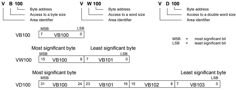
You can access data in most memory areas (V, I, Q, M, S, L, and SM) as bytes, words, or double words by using the byte-address format. To access a byte, word, or double word of data in the memory, you must specify the address in a way similar to specifying the address for a bit. This includes an area identifier, data size designation, and the starting byte address of the byte, word, or double-word value, as shown in Figure 4-5.
27
Data in other memory areas (such as T, C, HC, and the accumulators) are accessed by using an address format that includes an area identifier and a device number.
V B 100 Byte address Access to a byte size Area identifier
V W 100 Byte address Access to a word size Area identifier
V D 100 Byte address Access to a double word size Area identifier
VB100 MSB LSB 7 VB100 0
Most significant byte Least significant byte MSB LSB VW100 15 VB100 8 7 VB101 0
Most significant byte Least significant byte MSB LSB VD100 31 VB100 24 23 VB101 16 15 VB102 8 7 VB103 0
MSB = most significant bit LSB = least significant bit
Figure 4-5 Comparing Byte, Word, and Double-Word Access to the Same Address
Accessing Data in the Memory Areas
Process-Image Input Register: I The S7-200 samples the physical input points at the beginning of each scan cycle and writes these values to the process-image input register. You can access the process-image input register in bits, bytes, words, or double words:
Bit: I[byte address].[bit address] I0.1 Byte, Word, or Double Word: I[size][starting byte address] IB4
Process-Image Output Register: Q At the end of the scan cycle, the S7-200 copies the values stored in the process-image output register to the physical output points. You can access the process-image output register in bits, bytes, words, or double words:
Bit: Q[byte address].[bit address] Q1.1 Byte, Word, or Double Word: Q[size][starting byte address] QB5
Variable Memory Area: V You can use V memory to store intermediate results of operations being performed by the control logic in your program. You can also use V memory to store other data pertaining to your process or task. You can access the V memory area in bits, bytes, words, or double words:
Bit: V[byte address].[bit address] V10.2 Byte, Word, or Double Word: V[size][starting byte address] VW100
Bit Memory Area: M You can use the bit memory area (M memory) as control relays to store the intermediate status of an operation or other control information. You can access the bit memory area in bits, bytes, words, or double words:
Bit: M[byte address].[bit address] M26.7 Byte, Word, or Double Word: M[size][starting byte address] MD20
28
PLC Concepts Chapter 4
Timer Memory Area: T
The S7-200 provides timers that count increments of time in resolutions (time-base increments) of 1 ms, 10 ms, or 100 ms. Two variables are associated with a timer:
Current value: this 16-bit signed integer stores the amount of time counted by the timer. Timer bit: this bit is set or cleared as a result of comparing the current and the preset value. The preset value is entered as part of the timer instruction.
You access both of these variables by using the timer address (T + timer number). Access to either the timer bit or the current value is dependent on the instruction used: instructions with bit operands access the timer bit, while instructions with word operands access the current value. As shown in Figure 4-6, the Normally Open Contact instruction accesses the timer bit, while the Move Word instruction accesses the current value of the timer.
Format: T [timer number] T24
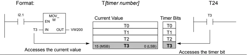
Figure 4-6 Accessing the Timer Bit or the Current Value of a Timer
Counter Memory Area: C
The S7-200 provides three types of counters that count each low-to-high transition event on the counter input(s): one type counts up only, one type counts down only, and one type counts both up and down. Two variables are associated with a counter:
Current value: this 16-bit signed integer stores the accumulated count. Counter bit: this bit is set or cleared as a result of comparing the current and the preset value. The preset value is entered as part of the counter instruction.
You access both of these variables by using the counter address (C + counter number). Access to either the counter bit or the current value is dependent on the instruction used: instructions with bit operands access the counter bit, while instructions with word operands access the current value. As shown in Figure 4-7, the Normally Open Contact instruction accesses the counter bit, while the Move Word instruction accesses the current value of the counter.
Format: C [counter number] C24
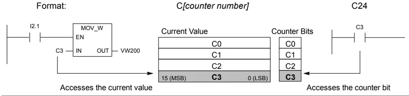
Figure 4-7 Accessing the Counter Bit or the Current Value of a Counter
29
S7-200 Programmable Controller System Manual
High-Speed Counters: HC
The high-speed counters count high-speed events independent of the CPU scan. High-speed counters have a signed, 32-bit integer counting value (or current value). To access the count value for the high-speed counter, you specify the address of the high-speed counter, using the memory type (HC) and the counter number (such as HC0). The current value of the high-speed counter is a read-only value and can be addressed only as a double word (32 bits).
Format: HC [high-speed counter number] HC 1
Accumulators: AC
The accumulators are read/write devices that can be used like memory. For example, you can use accumulators to pass parameters to and from subroutines and to store intermediate values used in a calculation. The S7-200 provides four 32-bit accumulators (AC0, AC1, AC2, and AC3). You can access the data in the accumulators as bytes, words, or double words.
The size of the data being accessed is determined by the instruction that is used to access the accumulator. As shown in Figure 4-8, you use the least significant 8 or 16 bits of the value that is stored in the accumulator to access the accumulator as bytes or words. To access the accumulator as a double word, you use all 32 bits.
For information about how to use the accumulators within interrupt subroutines, refer to the Interrupt Instructions in Chapter 6.
Format: AC[accumulator number] AC0
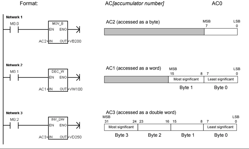
Figure 4-8 Accessing the Accumulators
30
PLC Concepts Chapter 4
Special Memory: SM
The SM bits provide a means for communicating information between the CPU and your program. You can use these bits to select and control some of the special functions of the S7-200 CPU, such as: a bit that turns on for the first scan cycle, a bit that toggles at a fixed rate, or a bit that shows the status of math or operational instructions. (For more information about the SM bits, see Appendix D.) You can access the SM bits as bits, bytes, words, or double words:
Bit: SM[byte address].[bit address] SM0.1 Byte, Word, or Double Word: SM[size][starting byte address] SMB86
Local Memory Area: L
The S7-200 provides 64 bytes of local memory of which 60 can be used as scratchpad memory or for passing formal parameters to subroutines.
Tip If you are programming in either LAD or FBD, STEP 7-Micro/WIN reserves the last four bytes of local memory for its own use.
Local memory is similar to V memory with one major exception. V memory has a global scope while L memory has a local scope. The term global scope means that the same memory location can be accessed from any program entity (main program, subroutines, or interrupt routines). The term local scope means that the memory allocation is associated with a particular program entity. The S7-200 allocates 64 bytes of L memory for the main program, 64 bytes for each subroutine nesting level, and 64 bytes for interrupt routines.
The allocation of L memory for the main program cannot be accessed from subroutines or from interrupt routines. A subroutine cannot access the L memory allocation of the main program, an interrupt routine, or another subroutine. Likewise, an interrupt routine cannot access the L memory allocation of the main program or of a subroutine.
The allocation of L memory is made by the S7-200 on an as-needed basis. This means that while the main portion of the program is being executed, the L memory allocations for subroutines and interrupt routines do not exist. At the time that an interrupt occurs or a subroutine is called, local memory is allocated as required. The new allocation of L memory might reuse the same L memory locations of a different subroutine or interrupt routine.
The L memory is not initialized by the S7-200 at the time of allocation and might contain any value. When you pass formal parameters in a subroutine call, the values of the parameters being passed are placed by the S7-200 in the appropriate L memory locations of the called subroutine. L memory locations, which do not receive a value as a result of the formal parameter passing step, will not be initialized and might contain any value at the time of allocation.
Bit: L[byte address].[bit address] L0.0 Byte, Word, or Double Word: L[size] [starting byte address] LB33
Analog Inputs: AI
The S7-200 converts an analog value (such as temperature or voltage) into a word-length (16-bit) digital value. You access these values by the area identifier (AI), size of the data (W), and the starting byte address. Since analog inputs are words and always start on even-number bytes (such as 0, 2, or 4), you access them with even-number byte addresses (such as AIW0, AIW2, or AIW4). Analog input values are read-only values.
Format: AIW[starting byte address] AIW4
Analog Outputs: AQ
The S7-200 converts a word-length (16-bit) digital value into a current or voltage, proportional to the digital value (such as for a current or voltage). You write these values by the area identifier (AQ), size of the data (W), and the starting byte address. Since analog outputs are words and always start on even-number bytes (such as 0, 2, or 4), you write them with even-number byte addresses (such as AQW0, AQW2, or AQW4). Analog output values are write-only values.
Format: AQW[starting byte address] AQW4
Sequence Control Relay (SCR) Memory Area: S
SCRs or S bits are used to organize machine operations or steps into equivalent program segments. SCRs allow logical segmentation of the control program. You can access the S bits as bits, bytes, words, or double words.
Bit: S [byte address].[bit address] S 3.1
Byte, Word, or Double Word: S [size][starting byte address] SB4
Format for Real Numbers
Real (or floating-point) numbers are represented as 32-bit, single-precision numbers, whose format is described in the ANSI/IEEE 754-1985 standard. See Figure 4-9. Real numbers are accessed in double-word lengths.
For the S7-200, floating point numbers are accurate up to 6 decimal places. Therefore, you can specify a maximum of 6 decimal places when entering a floating-point constant.

Figure 4-9 Format of a Real Number
Accuracy when Calculating Real Numbers
Calculations that involve a long series of values including very large and very small numbers can produce inaccurate results. This can occur if the numbers differ by 10 to the power of x, where x > 6.
For example: 100 000 000 + 1 = 100 000 000
Format for Strings
A string is a sequence of characters, with each character being stored as a byte. The first byte of the string defines the length of the string, which is the number of characters. Figure 4-10 shows the format for a string. A string can have a length of 0 to 254 characters, plus the length byte, so the maximum length for a string is 255 bytes. A string constant is limited to 126 bytes.
Figure 4-10 Format for Strings
Specifying a Constant Value for S7-200 Instructions
You can use a constant value in many of the S7-200 instructions. Constants can be bytes, words, or double words. The S7-200 stores all constants as binary numbers, which can then be represented in decimal, hexadecimal, ASCII, or real number (floating point) formats. See Table 4-2.
Table 4-2 Representation of Constant Values
| Representation | Format | Sample |
|---|---|---|
| Decimal | [decimal value] | 20047 |
| Hexadecimal | 16#[hexadecimal value] | 16#4E4F |
| Binary | 2#[binary number] | 2#1010_0101_1010_0101 |
| ASCII | '[ASCII text]' | 'ABCD' |
| Real | ANSI/IEEE 754-1985 | +1.175495E-38 (positive) -1.175495E-38 (negative) |
| String | "[stringtext]" | "ABCDE" |
Tip
The S7-200 CPU does not support “data typing” or data checking (such as specifying that the constant is stored as an integer, a signed integer, or a double integer). For example, an Add instruction can use the value in VW100 as a signed integer value, while an Exclusive Or instruction can use the same value in VW100 as an unsigned binary value.
Addressing the Local and Expansion I/O
The local I/O provided by the CPU provides a fixed set of I/O addresses. You can add I/O points to the S7-200 CPU by connecting expansion I/O modules to the right side of the CPU, forming an I/O chain. The addresses of the points of the module are determined by the type of I/O and the position of the module in the chain, with respect to the preceding input or output module of the same type. For example, an output module does not affect the addresses of the points on an input module, and vice versa. Likewise, analog modules do not affect the addressing of digital modules, and vice versa.
Tip
Process-image register space for digital I/O is always reserved in increments of eight bits (one byte). If a module does not provide a physical point for each bit of each reserved byte, these unused bits cannot be assigned to subsequent modules in the I/O chain. For input modules, the unused bits are set to zero with each input update cycle.
Analog I/O points are always allocated in increments of two points. If a module does not provide physical I/O for each of these points, these I/O points are lost and are not available for assignment to subsequent modules in the I/O chain.
Figure 4-11 provides an example of the I/O numbering for a particular hardware configuration. The gaps in the addressing (shown as gray italic text) cannot be used by your program.
| CPU 224XP | 4 In / 4 Out | 8 In | 4 Analog In 1 Analog Out | 8 Out | 4 Analog In 1 Analog Out |
|---|---|---|---|---|---|
| I0.0 Q0.0 | Module 0 | Module 1 | Module 2 | Module 3 | Module 4 |
| I0.1 Q0.1 | I2.0 Q2.0 | I3.0 | AIW4 AQW4 | Q3.0 | AIW12 AQW8 |
| I0.2 Q0.2 | I2.1 Q2.1 | I3.1 | AIW6 AQW6 | Q3.1 | AIW14 AQW10 |
| I0.3 Q0.3 | I2.2 Q2.2 | I3.2 | AIW8 | Q3.2 | AIW16 |
| I0.4 Q0.4 | I2.3 Q2.3 | I3.3 | AIW10 | Q3.3 | AIW18 |
| I0.5 Q0.5 | I2.4 Q2.4 | I3.4 | Q3.4 | ||
| I0.6 Q0.6 | I2.5 Q2.5 | I3.5 | Q3.5 | ||
| I0.7 Q0.7 | I2.6 Q2.6 | I3.6 | Q3.6 | ||
| I1.0 Q1.0 | I2.7 Q2.7 | I3.7 | Q3.7 | ||
| I1.1 Q1.1 | |||||
| I1.2 Q1.2 | |||||
| I1.3 Q1.3 | |||||
| I1.4 Q1.4 | |||||
| I1.5 Q1.5 | |||||
| I1.6 Q1.6 | |||||
| I1.7 Q1.7 | |||||
| AIW0 AQW0 | |||||
| AIW2 AQW2 | |||||
| Local I/O | Expansion I/O |
Figure 4-11 Sample I/O Addresses for Local and Expansion I/O (CPU 224XP)
Using Pointers for Indirect Addressing of the S7-200 Memory Areas
Indirect addressing uses a pointer to access the data in memory. Pointers are double word memory locations that contain the address of another memory location. You can only use V memory locations, L memory locations, or accumulator registers (AC1, AC2, AC3) as pointers. To create a pointer, you must use the Move Double Word instruction to move the address of the indirectly addressed memory location to the pointer location. Pointers can also be passed to a subroutine as a parameter.
The S7-200 allows pointers to access the following memory areas: I, Q, V, M, S, AI, AQ, SM, T (current value only), and C (current value only). You cannot use indirect addressing to access an individual bit or to access HC or L memory areas.
To indirectly access the data in a memory address, you create a pointer to that location by entering an ampersand (&) and the memory location to be addressed. The input operand of the instruction must be preceded with an ampersand (&) to signify that the address of a memory location, instead of its contents, is to be moved into the location identified in the output operand of the instruction (the pointer).
Entering an asterisk (*) in front of an operand for an instruction specifies that the operand is a pointer. As shown in Figure 4-12, entering *AC1 specifies that AC1 is a pointer to the word-length value being referenced by the Move Word (MOVW) instruction. In this example, the values stored in both VB200 and VB201 are moved to accumulator AC0.
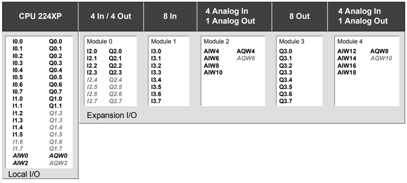
Figure 4-12 Creating and Using a Pointer
34

As shown in Figure 4-13, you can change the value of a pointer. Since pointers are 32-bit values, use double-word instructions to modify pointer values. Simple mathematical operations, such as adding or incrementing, can be used to modify pointer values.
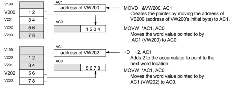
Figure 4-13 Modifying a Pointer
Tip
Remember to adjust for the size of the data that you are accessing: to access a byte, increment the pointer value by 1; to access a word or a current value for a timer or counter, add or increment the pointer value by 2; and to access a double word, add or increment the pointer value by 4.
Sample Program for Using an Offset to Access Data in V Memory
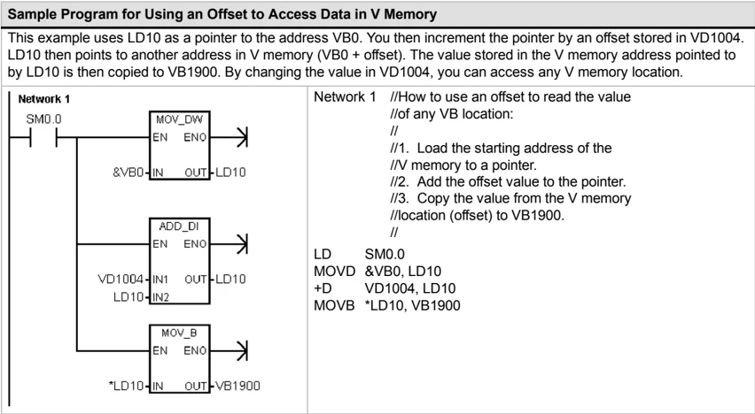
This example uses LD10 as a pointer to the address VB0. You then increment the pointer by an offset stored in VD1004. LD10 then points to another address in V memory (VB0 + offset). The value stored in the V memory address pointed to by LD10 is then copied to VB1900. By changing the value in VD1004, you can access any V memory location.
| Network 1 | Network 1 //How to use an offset to read the value //of any VB location: // //1. Load the starting address of the //V memory to a pointer. //2. Add the offset value to the pointer. //3. Copy the value from the V memory //location (offset) to VB1900. // LD SM0.0 MOVD &VB0, LD10 +D VD1004, LD10 MOVB *LD10, VB1900 |
|---|---|
Sample Program for Using a Pointer to Access Data in a Table
This example uses LD14 as a pointer to a recipe stored in a table of recipes that begins at VB100. In this example, VW1008 stores the index to a specific recipe in the table. If each recipe in the table is 50 bytes long, you multiply the index by 50 to obtain the offset for the starting address of a specific recipe. By adding the offset to the pointer, you can access the individual recipe from the table. In this example, the recipe is copied to the 50 bytes that start at VB1500.
| Network 1 | Network 1 //How to transfer a recipe from a table of recipes: |
|---|---|
| // - Each recipe is 50 bytes long. | |
| // - The index parameter (VW1008) identifies | |
| // the recipe to be loaded. | |
| // | |
| //1. Create a pointer to the starting address | |
| // of the recipe table. | |
| //2. Convert the index of the recipe to a | |
| // double-word value. | |
| //3. Multiply the offset to accommodate | |
| // the size of each recipe. | |
| //4. Add the adjusted offset to the pointer. | |
| //5. Transfer the selected recipe to | |
| // VB1500 through VB1549. | |
| LD SM0.0 | |
| MOVD &VB100, LD14 | |
| ITD VW1008, LD18 | |
| *D +50, LD18 | |
| +D LD18, LD14 | |
| BMB *LD14, VB1500, 50 |
Understanding How the S7-200 Saves and Restores Data
The S7-200 provides a variety of features to ensure that your user program and data are properly retained in the S7-200.
-
Retentive Data Memory – Areas of data memory the user selects to remain unchanged over a power cycle, as long as the super capacitor and the optional battery cartridge have not been discharged. V, M, Timer Currents, and Counter Currents are the only data memory areas that are configurable to be retentive.
-
Permanent Memory – Non-volatile memory used to store the program block, data block, system block, forced values, M memory configured to be saved on loss of power, and selected values written under user program control
-
Memory Cartridge – Removable non-volatile memory used to store the program block, data block, system block, recipes, data logs, and forced values
You can use the S7-200 Explorer to store documentation files (doc, text, pdf, etc.) into the cartridge. You can also use the S7-200 Explorer to perform general file maintenance on the memory cartridge (copy, delete, directory and launch).
To install a memory cartridge, remove the plastic slot cover from the S7-200 CPU and insert the memory cartridge in the slot. The memory cartridge is keyed for proper installation.
Caution
Electrostatic discharge can damage the memory cartridge or the receptacle on the S7-200 CPU. Make contact with a grounded conductive pad and/or wear a grounded wrist strap when you handle the cartridge. Store the cartridge in a conductive container.
36