As shown in Table 7-13, the S7-200 CPU or EM 277 provide a specific number of connections. Each port (Port 0 and Port 1) of an S7-200 CPU supports up to four separate connections. (This allows a maximum of eight connections for the S7-200 CPU.) This is in addition to the shared PPI connection. An EM 277 supports six connections. Each port reserves one connection for a programmer and one connection for an operator panel (OP or TP). The remaining connections are available for general use.
Table 7-13 Capabilities of the S7-200 CPU and EM 277 Modules
| Connection Point | Baud Rate | Connections | STEP 7-Micro/WIN Protocol Profile Selections |
|---|---|---|---|
| S7-200 CPU Port 0 | 9.6 kbaud, 19.2 kbaud, or 187.5 kbaud | 4 | PPI, PPI Advanced, MPI, and PROFIBUS¹ |
| Port 1 | 9.6 kbaud, 19.2 kbaud, or 187.5 kbaud | 4 | PPI, PPI Advanced, MPI, and PROFIBUS¹ |
| EM 277 Module | 9.6 kbaud to 12 Mbaud | 6 per module² | PPI Advanced, MPI, and PROFIBUS |
¹ If a CP card is used to connect STEP 7-Micro/WIN to the S7-200 CPU through Port 0 or Port 1, you can select either MPI or DP PROFIBUS profiles only when the S7-200 device is configured as a slave.
² In addition to the PROFIBUS connection.
Working with Complex Networks
For the S7-200, complex networks typically have multiple S7-200 masters that use the Network Read (NETR) and Network Write (NETW) instructions to communicate with other devices on a PPI network. Complex networks typically present special problems that can block a master from communicating with a slave.
If the network is running at a lower baud rate (such as 9.6 kbaud or 19.2 kbaud), then each master completes the transaction (read or write) before passing the token. At 187.5 kbaud, however, the master issues a request to a slave and then passes the token, which leaves an outstanding request at the slave.
Figure 7-33 shows a network with potential communications conflicts. In this network, Station 1, Station 2, and Station 3 are masters, using the Network Read or Network Write instructions to communicate with Station 4. The Network Read and Network Write instructions use PPI protocol so all of the S7-200s share the single PPI connection in Station 4.
In this example, Station 1 issues a request to Station 4. For baud rates above 19.2 kbaud, Station 1 then passes the token to Station 2. If Station 2 attempts to issue a request to Station 4, the request from Station 2 is rejected because the request from Station 1 is still present. All requests to Station 4 will be rejected until Station 4 completes the response to Station 1. Only after the response has been completed can another master issue a request to Station 4.
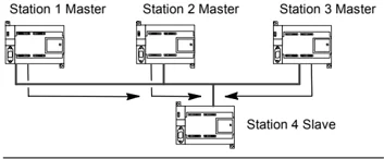
Figure 7-33 Communications Conflict
To avoid this conflict for the communications port on Station 4, consider making Station 4 the only master on the network, as shown in Figure 7-34. Station 4 then issues the read/write requests to the other S7-200s.
Not only does this configuration ensure that there is no conflict in communications, but it also reduces the overhead caused by having multiple masters and allows the network to operate more efficiently.
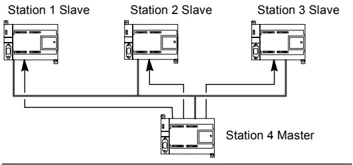
Figure 7-34 Avoiding Conflict
For some applications, however, reducing the number of masters on the network is not an option. When there are several masters, you must manage the token rotation time and ensure that the network does not exceed the target token rotation time. (The token rotation time is the amount of time that elapses from when a master passes the token until that master receives the token again.)
If the time required for the token to return to the master is greater than a target token rotation time, then the master is not allowed to issue a request. The master can issue a request only when the actual token rotation time is less than the target token rotation time.
The highest station address (HSA) and the baud rate settings for the S7-200 determine the target token rotation time. Table 7-14 lists target rotation times.
For the slower baud rates, such as 9.6 kbaud and 19.2 kbaud, the master waits for the response to its request before passing the token. Because processing the request/response cycle can take a relatively long time in terms of the scan time, there is a high probability that every master on the network can have a request ready to transmit every time it holds the token. The actual token rotation time would then increase, and some masters might not be able to process any requests. In some situations, a master might only rarely be allowed to process requests.
For example: Consider a network of 10 masters that transmit 1 byte at 9.6 kbaud that is configured with an HSA of 15. For this example, each of the masters always has a message ready to send. As shown in Table 7-14, the target rotation time for this network is 0.613 s. However, based on the performance data listed in Table 7-12, the actual token rotation time required for this network is 1.48 s. Because the actual token rotation time is greater than the target token rotation time, some of the masters will not be allowed to transmit a message until some later rotation of the token.
You have two basic options for improving a situation where the actual token rotation time is greater than the target token rotation time:
- You can reduce actual token rotation time by reducing the number of masters on your network. Depending on your application, this might not be a feasible solution.
- You can increase the target token rotation time by increasing the HSA for all of the master devices on the network.
Increasing the HSA can cause a different problem for your network by affecting the amount of time that it takes for a S7-200 to switch to master mode and enter the network. If you use a timer to ensure that the Network Read or Network Write instruction completes its execution within a specified time, the delay in initializing master mode and adding the S7-200 as a master on the network can cause the instruction to time out. You can minimize the delay in adding masters by reducing the Gap Update Factor (GUF) for all masters on the network.
Because of the manner in which requests are posted to and left at the slave for 187.5 kbaud, you should allow extra time when selecting the target token rotation time. For 187.5 kbaud, the actual token rotation time should be approximately half of the target token rotation time.
To determine the token rotation time, use the performance data in Table 7-12 to determine the time required for completing the Network Read and Network Write operations. To calculate the time required for HMI devices (such as the TD 200), use the performance data for transferring 16 bytes. Calculate the token rotation time by adding the time for each device on the network. Adding all of the times together describes a worst-case scenario where all devices want to process a request during the same token rotation. This defines the maximum token rotation time required for the network.
Table 7-14 HSA and Target Token Rotation Time
| HSA | 9.6 kbaud | 19.2 kbaud | 187.5 kbaud |
|---|---|---|---|
| HSA=15 | 0.613 s | 0.307 s | 31 ms |
| HSA=31 | 1.040 s | 0.520 s | 53 ms |
| HSA=63 | 1.890 s | 0.950 s | 97 ms |
| HSA=126 | 3.570 s | 1.790 s | 183 ms |
For example: Consider a network running at 9.6 kbaud with four TD 200s and four S7-200s, with each S7-200 writing 10 bytes of data to another S7-200 every second. Use Table 7-12 to calculate the specific transfer times for the network:
4 TD 200 devices transferring 16 bytes of data = 0.66 s 4 S7-200s transferring 10 bytes of data = 0.63 s Total token rotation time = 1.29 s
To allow enough time for this network to process all requests during one token rotation, set the HSA to 63. (See Table 7-14.) Selecting a target token rotation (1.89 s) that is greater than the maximum token rotation time (1.29 s) ensures that every device can transfer data on every rotation of the token.
To help improve the reliability of a multi-master network, you should also consider the following actions:
Change the update rate for the HMI devices to allow more time between updates. For example, change the update rate for a TD 200 from "As fast as possible" to "Once per second."
Reduce the number of requests (and the network overhead for processing the requests) by combining the operations of Network Read or Network Write operations. For example, instead of using two Network Read operations that read 4 bytes each, use one Network Read operation that reads 8 bytes. The time to process the two requests of 4 bytes is much greater than the time to process one request for 8 bytes.
Change the update rate of the S7-200 masters so that they do not attempt to update faster than the token rotation time.
238
Configuring the RS-232/PPI Multi-Master Cable for Remote Operation
HyperTerminal as a Configuration Tool
If STEP 7-Micro/WIN is not available for you to use to configure the RS-232/PPI Multi-Master cable for remote operation, you can use HyperTerminal or any other dumb terminal package. The RS-232/PPI Multi-Master cable provides built-in menus to guide you as you configure the cable for remote operation.
While configuring the RS-232/PPI Multi-Master cable with HyperTerminal, you must connect the RS-485 connector to an S7-200 CPU. This is the source of the 24V power required for the cable to operate. Be sure to supply power to the S7-200 CPU.
To invoke HyperTerminal on your PC, click on Start > Programs > Accessories > Communications > HyperTerminal.
HyperTerminal application launches and prompts for a Connection Description. You must supply a name for the connection (for example, Multi-Master). Click OK. You can select an icon or accept the default icon provided with the new connection. See Figure 7-35.
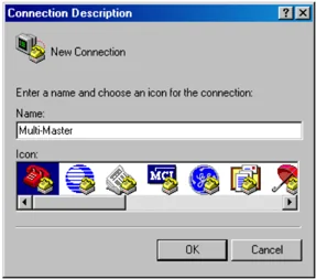
Figure 7-35 HyperTerminal Connection Description
The Connect To screen is displayed. Select the communications port that you will be using and click OK. The next screen displayed is COMx Properties. Accept the default and click OK. See Figure 7-36.
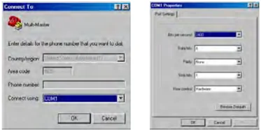
Figure 7-36 HyperTerminal Connect To Screen and COMx Properties Screen
After clicking OK, your cursor is placed in the edit window of the HyperTerminal screen as shown in Figure 7-37. Notice that the status bar at the bottom of the HyperTerminal window indicates that you are connected and a timer is running to indicate the duration of the connection.
From the menu, select Call > Disconnect. The status bar now indicates you are disconnected.
Select View > Font. Select Courier New and click OK.
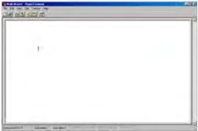
Figure 7-37 Multi-Master HyperTerminal Edit Window
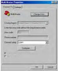
Select File > Properties. On the Connect To tab, click the Configure ... button to display the communication port properties. See Figure 7-38.
In the COMx Properties dialog, select the baud rate from the drop down menu for Bits per second. You must choose a baud rate from 9600 to115200 bits per second (typically, 9600). Select 8 data bits, no parity, one stop bit and no flow control by using the appropriate drop down menus.
Click OK to return to the Connect To tab.
 Figure 7-38 Multi-Master Properties and COMx Properties
Select the Settings tab. In the Emulation drop down menu, select ANSI and click OK. This will return you to the edit window of the HyperTerminal screen. The status bar at the bottom of the screen should indicate: "Disconnected ANSI 9600 8-N-1" as shown in Figure 7-39.
 Figure 7-39 HyperTerminal Edit - Disconnect ANSI
To initiate communication with the RS-232/PPI Multi-Master cable, type "hhh". The Rx LED on the cable should blink on for about a second as you type "hhh". The TX LED turns on briefly as the cable responds with a choice of languages.
Enter the number that corresponds to your choice of language (use the backspace key to eliminate the default selection) and depress the ENTER key. Figure 7-40 shows the language selection display and the RS232/PPI Cable Setup for Remote Operation selection display.
This display also shows the firmware revision of the cable.
 Figure 7-40 HyperTerminal Language Selection and RS-232/PPI Cable Setup
240
The RS232/PPI Cable Setup for Remote Operation display guides you through the steps required to configure the cable for the type of remote operation you desire.
If you have an earlier version of STEP 7-Micro/WIN, select option 2 "PPI single master network with a modem".
If you are using Freeport communication with a modem, select option 3.
For example, select option 1 for PPI multi-master network with a modem using STEP 7-Micro/WIN 3.2 Service Pack 4 or later.
The HyperTerminal display shown in Figure 7-41 indicates the switch settings you need to set on the cable. The switch settings allow STEP 7-Micro/WIN to participate in a remote network via modems with one or more masters and one or more S7-200 PLCs. Such a network is shown in Figure 7-41.
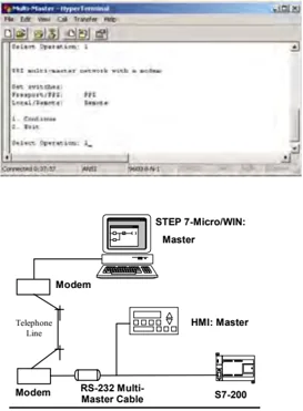
Figure 7-41 HyperTerminal - RS-232/PPI Cable Setup
After setting the switches as indicated, select continue. The resulting HyperTerminal display is shown in Figure 7-42.
The remote modem (the one connected to the RS-232/PPI Multi-Master cable) should be set to factory defaults. With the remote modem set to factory defaults, enter the AT strings required to program the modem for operation with the RS-232/PPI Multi-Master cable. Typically, the only string that needs to be sent is ATS0=1, which configures the modem to auto-answer incoming calls on the first ring.
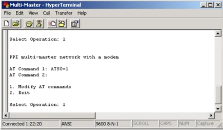
Figure 7-42 HyperTerminal - Remote Modem
If you are using a cell modem that requires a PIN, use the second AT command to supply the PIN (refer to your modem manual for the AT commands supported by your modem). If you need to modify the AT commands, make the selection and enter the commands required as you are prompted for them. The prompts include example AT command strings to help you with the formatting of the commands.
The RS-232/PPI Multi-Master cable will send these AT strings to the modem each time the cable powers up. Make sure that the modem is powered up before or very close to the same time the cable is powered up. Also, if you power cycle the modem, be sure to power cycle the cable. This allows the cable to properly configure the modem and operate at the highest available baud rate.
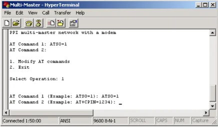
The HyperTerminal displays in Figure 7-43 show how to enter the AT commands. If you do not need to supply a second AT command at the prompt, press the ENTER key. This returns you to the selection for modifying the AT commands or exiting. If you finished entering the AT commands select Exit.
After exiting the HyperTerminal configuration of the RS-232/PPI Multi-Master cable, disconnect the cable from the PC and connect it to the modem. Power cycle both the modem and the cable. You are now ready to use the cable for remote operation in a PPI multi-master network.
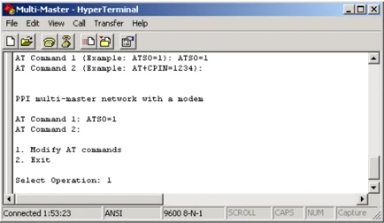
Figure 7-43 HyperTerminal - AT Commands
Freeport Operation with HyperTerminal
Configuring the RS-232/PPI Multi-Master cable for Freeport operation using HyperTerminal is very similar to the example configuration described above. Follow the prompts to configure the cable according to your needs.
242
Hardware Troubleshooting Guide and Software Debugging Tools
STEP 7-Micro/WIN provides software tools to help you debug and test your program. These features include viewing the status of the program as it is executed by the S7-200, selecting to run the S7-200 for a specified number of scans, and forcing values.
Use Table 8-1 as a guide for determining the cause and possible solution when troubleshooting problems with the S7-200 hardware.
I n This Chapter
- Features for Debugging Your Program . . . . . . . . . . . . . . . . . . . . . . . . . . . . . . . . . . . . . . . . . . . . . . . . . . . . . . . . . . . . . . . . . . . . . . . . . . . . . . . . . . . . . . . . . . . . . . . . . . . . . . . . . . . . . . . . . . . . . . . . ........ 244
- Displaying the Program Status . . . . . . . . . . . . . . . . . . . . . . . . . . . . . . . . . . . . . . . . . . . . . . . . . . . . . . . . . . . . . . . . . . . . . . . . . . . . . . . . . . . . . . . . . . . . . . ........ 246
- Using a Status Chart to Monitor and Modify the Data in the S7-200 . . . . . . . . . . . . . . . . . . . . . . . . . . . . . . . . . . . . . . . . . . . . . . . . . . . . . . . . . . . . . . . . . . . . . . . . . . . . . . . . . . . . . . . . . . . . . . . . . . . . . . . . . . . . . . . . . . . . . . . . . . . . . . . . . . . . . . . . . . . . . . . . . . . . . . . . . . . . . . . . . . . . . . . . . . . . . . . . . . . . . . . . . . . . . . . . . . . . . . . . . . . . . . . . . . . . . . . . . ........
Features for Debugging Your Program
STEP 7-Micro/WIN provides several features to help you debug your program: bookmarks, cross reference tables, and run mode edits.
Using Bookmarks for Easy Program Access
You can set bookmarks in your program to make it easy to move back and forth between designated (bookmarked) lines of a long program. You can move to the next or the previous bookmarked line of your program.
Using the Cross Reference Table to Check Your Program References
The cross reference table allows you to display the cross references and element usage information for your program.
Cross Reference
The cross reference table identifies all operands used in the program, and identifies the program block, network or line location, and instruction context of the operand each time it is used.
You can toggle between symbolic and absolute view to change the representation of all operands.
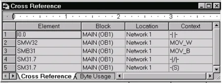
Figure 8-1 Cross Reference Table
Tip Double-clicking on an element in the cross reference table takes you to that part of your program or block.
Editing Your Program in RUN Mode
The S7-200 CPUs Rel. 2.0 (and higher) models support RUN mode edits. The RUN mode edit capability is intended to allow you to make small changes to a user program with minimal disturbance to the process being controlled by the program. However, implementing this capability also allows massive program changes that could be disruptive or even dangerous.
Warning When you download changes to an S7-200 in RUN mode, the changes immediately affect process operation. Changing the program in RUN mode can result in unexpected system operation, which could cause death or serious injury to personnel, and/or damage to equipment. Only authorized personnel who understand the effects of RUN mode edits on system operation should perform a RUN mode edit.
To perform a program edit in RUN mode, the online S7-200 CPU must support RUN mode edits and must be in RUN mode.
- Select the Debug > Program Edit in RUN menu command.
- If the project is different than the program in the S7-200, you are prompted to save it. The RUN mode edit can be performed only on the program in the S7-200.
- STEP 7-Micro/WIN alerts you about editing your program in RUN mode and prompts you to either continue or to cancel the operation. If you click Continue, STEP 7-Micro/WIN uploads the program from the S7-200. You can now edit your program in RUN mode. No restrictions on edits are enforced.
244
Hardware Troubleshooting Guide and Software Debugging Tools Chapter 8
Tip Positive (EU) and Negative (ED) transition instructions are shown with an operand. To view information about edge instructions, select the Cross Reference icon in the View. The Edge Usage tab lists numbers for the edge instructions in your program. Be careful not to assign duplicate edge numbers as you edit your program.
Downloading the Program in RUN Mode
RUN-mode editing allows you to download only your program block while the S7-200 is in RUN mode. Before downloading the program block in RUN mode, consider the effect of a RUN-mode modification on the operation of the S7-200 for the following situations:
If you deleted the control logic for an output, the S7-200 maintains the last state of the output until the next power cycle or transition to STOP mode.
If you deleted a high-speed counter or pulse output functions which were running, the high-speed counter or pulse output continues to run until the next power cycle or transition to STOP mode.
If you deleted an Attach Interrupt instruction but did not delete the interrupt routine, the S7-200 continues to execute the interrupt routine until a power cycle or a transition to STOP mode. Likewise, if you deleted a Detach Interrupt instruction, the interrupts are not shut down until the next power cycle or transition to STOP mode.
If you added an Attach Interrupt instruction that is conditional on the first scan bit, the event is not activated until the next power cycle or STOP-to-RUN mode transition.
If you deleted an Enable Interrupt instruction, the interrupts continue to operate until the next power cycle or transition from RUN to STOP mode.
If you modified the table address of a receive box and the receive box is active at the time that the S7-200 switches from the old program to the modified program, the S7-200 continues to write the data received to the old table address. Network Read and Network Write instructions function in the same manner.
Any logic that is conditional on the state of the first scan bit will not be executed until the next power cycle or transition from STOP to RUN mode. The first scan bit is set only by the transition to RUN mode and is not affected by a RUN-mode edit.
Tip Before you can download your program in RUN mode, the S7-200 must support RUN mode edits, the program must compile with no errors, and the communications between STEP 7-Micro/WIN and the S7-200 must be error-free.
You can download only the program block.
To download your program in RUN mode, click on the Download button or select the File > Download menu command. If the program compiles successfully, STEP 7-Micro/WIN downloads the program block to the S7-200.
Exiting RUN-Mode Edit
To exit RUN-mode editing, select the Debug > Program Edit in RUN menu command and deselect the checkmark. If you have changes that have not been saved, STEP 7-Micro/WIN prompts you either to continue editing, to download changes and exit RUN-mode editing, or to exit without downloading.
245
S7-200 Programmable Controller System Manual
Displaying the Program Status
STEP 7-Micro/WIN allows you to monitor the status of the user program as it is being executed. When you monitor the program status, the program editor displays the status of instruction operand values.
To display the status, click the Program Status button or select the Debug > Program Status menu command.
Displaying the Status of the Program in LAD and FBD
STEP 7-Micro/WIN provides two options for displaying the status of LAD and FBD programs:
End of scan status: STEP 7-Micro/WIN acquires the values for the status display across multiple scan cycles and then updates the status screen display. The status display does not reflect the actual status of each element at the time of execution. The end-of-scan status does not show status for L memory or for the accumulators.
For end of scan status, the status values are updated in all of the CPU operating modes.
Execution status: STEP 7-Micro/WIN displays the values of the networks as the elements are executed in the S7-200. For displaying the execution status, select the Debug > Use Execution Status menu command.
For execution status, the status values are updated only when the CPU is in RUN mode.
Tip STEP 7-Micro/WIN provides a simple method for changing the state of a variable. Simply select the variable and right-click to display a menu of options.
Configuring How the Status is Displayed in the LAD and FBD Program
STEP 7-Micro/WIN provides a variety of options for displaying the status in the program.
To configure the display option for the status screen, select the Tools > Options menu command, select Program Editor and click on the Program Editor tab, as shown in Figure 8-2.
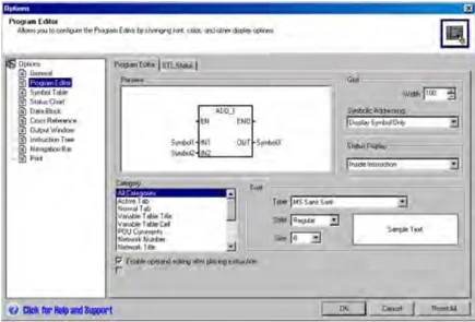
Figure 8-2 Options for the Status Display
246
Hardware Troubleshooting Guide and Software Debugging Tools Chapter 8
Displaying the Status of the Program in STL
You can monitor the execution status of your STL program on an instruction-by-instruction basis. For an STL program, STEP 7-Micro/WIN displays the status of the instructions that are displayed on the screen.
STEP 7-Micro/WIN gathers status information from the S7-200, beginning from the first STL statement at the top of the editor window. As you scroll down the editor window, new information is gathered from the S7-200.
STEP 7-Micro/WIN continuously updates values on the screen. To halt the screen updates, select the Triggered Pause button. The current data remains on the screen until you deselect the Triggered Pause button.
Configuring Which Parameters Are Displayed in the STL Program
STEP 7-Micro/WIN allows you to display the status of a variety of parameters for the STL instructions. Select the Tools > Options menu command, select Program Editor, and click on the STL Status tab. See Figure 8-3.
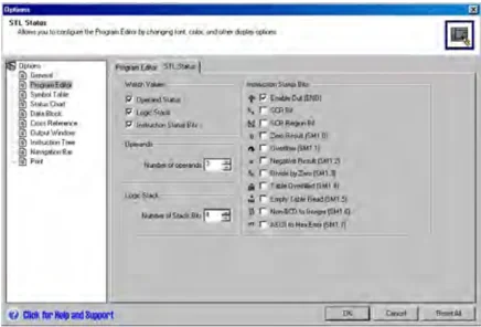
Figure 8-3 Options for Displaying STL Status
Using a Status Chart to Monitor and Modify the Data in the S7-200
The Status Chart allows you to read, write, force, and monitor variables while the S7-200 is executing your program. Select the View > Component > Status Chart menu command to create a status chart. Figure 8-4 shows a sample status chart.
You can create multiple status charts.
STEP 7-Micro/WIN provides toolbar icons for manipulating the status chart: Sort Ascending, Sort Descending, Single Read, Write All, Force, Unforce, Unforce All, and Read All Forced.
To select a format for a cell, select the cell and click the right mouse button to display the context menu.
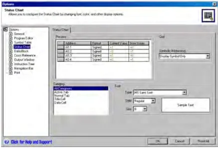
Figure 8-4 Status Chart
247
Forcing Specific Values
The S7-200 allows you to force any or all of the I/O points (I and Q bits). In addition, you can also force up to 16 memory values (V or M) or analog I/O values (AI or AQ). V memory or M memory values can be forced in bytes, words, or double words. Analog values are forced as words only, on even-numbered byte boundaries, such as AIW6 or AQW14. All forced values are stored in the permanent memory of the S7-200.
Because the forced data might be changed during the scan cycle (either by the program, by the I/O update cycle, or by the communications- processing cycle), the S7-200 reapplies the forced values at various times in the scan cycle.
Reading the inputs: The S7-200 applies the forced values to the inputs as they are read.
Executing the control logic in the program: The S7-200 applies the forced values to all immediate I/O accesses. Forced values are applied for up to 16 memory values after the program has been executed.
Processing any communications requests: The S7-200 applies the forced values to all read/write communications accesses.
Writing to the outputs: The S7-200 applies the forced values to the outputs as they are written.
 Writes to the outputs
Perform the CPU Diagnostics
Process any Communications Requests
Execute the Program
Scan Cycle
Reads the inputs
Figure 8-5 S7-200 Scan Cycle
You can use the Status Chart to force values. To force a new value, enter the value in the New Value column of the Status Chart, then press the Force button on the toolbar. To force an existing value, highlight the value in the Current Value column, then press the Force button.
Tip The Force function overrides a Read Immediate or Write Immediate instruction. The Force function also overrides the output table that was configured for transition to STOP mode. If the S7-200 goes to STOP mode, the output reflects the forced value and not the value that was configured in the output table.
Running Your Program for a Specified Number of Scans
To help you debug your program, STEP 7-Micro/WIN allows you to run the program for a specific number of scans.
You can have the S7-200 execute only the first scan. This allows you to monitor the data in the S7-200 after the first scan. Select the Debug > First Scan menu command to run the first scan.
You can have the S7-200 execute your program for a limited number of scans (from 1 scan to 65,535 scans). This allows you to monitor the program as it changes variables. Select the Debug > Multiple Scans menu command to specify the number of scans to be executed.
248
Hardware Troubleshooting Guide
Table 8-1 Troubleshooting Guide for the S7-200 Hardware
Open Loop Motion Control with the S7-200
The S7-200 provides three methods of open loop motion control:
☐ Pulse Width Modulation (PWM) – built into the S7-200 for speed, position or duty cycle control
☐ Pulse Train Output (PTO) – built into the S7-200 for speed and position control
☐ EM 253 Position Module – an add on module for speed and position control
To simplify the use of position control in your application, STEP 7-Micro/WIN provides a Position Control wizard that allows you to completely configure the PWM, PTO or Position module in minutes. The wizard generates position instructions that you can use to provide dynamic control of speed and position in your application. For the Position module STEP 7-Micro/WIN also provides a control panel that allows you to control, monitor and test your motion operations.
I n This Chapter
-
Overview . . . . . . . . . . . . . . . . . . . . . . . . . . . . . . . . . . . . . . . . . . . . . . . . . . . . . . . . . . . . . . . . . . . . . . . . . . . . . . . . . . . . . . . . . . . . . . . . . . . . . . . . . . . . . . . . . . . . . . . . . . . . . . . . . . . . . . . . . . . . . . . . . . . . . . . . . . . . . . . . . . . . . . . . . . . . . . . . . . . . . . . . . . . . . . . . . . . . . . . . ........ 252
-
Using the PWM (Pulse Width Modulation) Output . . . . . . . . . . . . . . . . . . . . . . . . . . . . . . . . . . . . . . . . . . . . . . . . . . . . . . . . . . . . . . . . . . . . . . . . . . . . . . . . . . . . . . . . . . . . . . . . ........ 253
-
Basic Information for Open Loop Position Control Using Steppers or Servos . . . . . . . . . . . . . . . . . . . . . . . . . . . . . . . . . . . . . . . . . . . . . . . . . . . . . . . . . . . . . . . . . . . . . . . . . . . . . . . . . . . . . . . . . . . . . . . . . . . . . . . . . . . . . . . . . . . . . . . . . . . . . . . . . . . . . . . . . . . . . . . . . . . . . . . . . . . . . . . . . . . . . . . . . . . . . . . . . . . . . . . . . . . . . . . . . . . . . . . . . . . . . . . . . . ........

Overview
The S7-200 provides three methods of open loop motion control:
☐ Pulse Width Modulation (PWM) – built into the S7-200 for speed, position or duty cycle control
☐ Pulse Train Output (PTO) – built into the S7-200 for speed and position control
☐ EM 253 Position Module – an add on module for speed and position control
 Position
Control
The S7-200 provides two digital outputs (Q0.0 and Q0.1) that can be configured using the Position Control Wizard for use as either PWM or a PTO outputs. The Position Control Wizard can also be used to configure the EM 253 Position Module.
When an output is configured for PWM operation, the cycle time of the output is fixed and the pulse width or duty cycle of the pulse is controlled by your program. The variations in pulse width can be used to control the speed or position in your application.
When an output is configured for PTO operation, a 50% duty cycle pulse train is generated for open loop control of the speed and position for either stepper motors or servo motors. The built in PTO function only provides the pulse train output. Direction and limit controls must be supplied by your application program using I/O built into the PLC or provided by expansion modules.
The EM 253 Position Module provides a single pulse train output with integrated direction control, disable and clear outputs. It also includes dedicated inputs which allow the module to be configured for several modes of operation including automatic reference point seek. The module provides a unified solution for open loop control of the speed and position for either stepper motors or servo motors.
To simplify the use of position control in your application, STEP 7-Micro/WIN provides a Position Control wizard that allows you to completely configure the PWM, PTO or Position module in minutes. The wizard generates position instructions that you can use to provide dynamic control of speed and position in your application. For the Position module STEP 7-Micro/WIN also provides a control panel that allows you to control, monitor and test your motion operations.
252
Using the PWM (Pulse Width Modulation) Output
PWM provides a fixed cycle time output with a variable duty cycle. The PWM output runs continuously after being started at the specified frequency (cycle time). The pulse width is varied as required to effect the desired control. Duty cycle can be expressed as a percentage of the cycle time or as a time value corresponding to pulse width. The pulse width can vary from 0% (no pulse, always off) to 100% (no pulse, always on). See Figure 9-1.
Since the PWM output can be varied from 0% to 100%, it provides a digital output that in many ways is analogous to an analog output. For example the PWM output can be used to control the speed of a motor from stop to full speed or it can be used to control position of a valve from closed to full open.
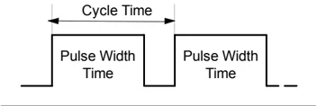
Figure 9-1 Pulse Width Modulation (PWM)
Configuring the PWM Output
To configure one of the built-in outputs for PWM control, use the Position Control wizard. To start the Position Control wizard, either click the Tools icon in the navigation bar and then double-click the Position Control Wizard icon, or select the Tools> Position Control Wizard menu command. See Figure 9-2
- Select the option to configure the onboard PTO/PWM operation for the S7-200 PLC.
- Choose the output Q0.0 or Q0.1 that you wish to configure as a PWM output.
- Next select Pulse Width Modulation (PWM) from the drop down dialog box, select the time base of microseconds or milliseconds and specify the cycle time.
- Select Finish to complete the wizard.
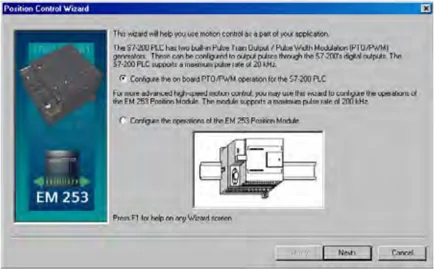
Figure 9-2 Configuring the PWM Output
The wizard will generate one instruction for you to use to control the duty cycle of the the PWM output.
PWMx_RUN Instruction
The PWMx_RUN instruction allows you to control the duty cycle of the output by varying the pulse width from 0 to the pulse width of the cycle time.
The Cycle input is a word value that defines the cycle time for the PWM output. The allowed range is from 2 to 65535 units of the time base (microseconds or milliseconds) that was specified within the wizard.
The Duty_Cycle input is a word value that defines the pulse width for the PWM output. The allowed range of values is from 0.0 to 65535 units of the time base (microseconds or milliseconds) that was specified within the wizard.
The Error is a byte value returned by the PWMx_RUN instruction that indicates the result of execution. See Table for a description of the possible error codes.
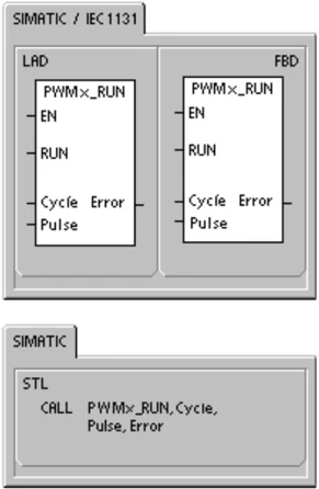
Table 9-1 Parameters for the PWMx_RUN Instruction \begin{tabular}{|l|l|l|} \hline Inputs/Outputs & Data Types & Operands \ \hline Cycle, Duty_Cycle & Word & IW, QW, VW, MW, SMW, SW, T, C, LW, AC, AIW, *VD, *AC, *LD, Constant \ \hline Error & Byte & IB, QB, VB, MBV, SMB, LB, AC, *VD, *AC, *LD, Constant \ \hline \end{tabular}
Table 9-2 PWMx_RUN Instruction Error Codes \begin{tabular}{|l|l|} \hline Error Code & Description \ \hline 0 & No error, normal completion \ \hline 1 & Immediate STOP issued during move. STOP command completed successfully \ \hline \end{tabular}
Open Loop Motion Control with the S7-200 Chapter 9
Basic Information for Open Loop Position Control Using Steppers or Servos
Both the PTO built-in to the S7-200 PLC and the EM 253 Position Module use a pulse train output to control both the speed and position of a stepper motor or a servo motor.
Using the PTO or the module for open loop position control requires expertise in the field of motion control. This chapter is not meant to educate the novice in this subject. However, it provides fundamental information that will help as you use the Position Control wizard to configure the PTO or module for your application.
Maximum and Start/Stop Speeds
The wizard will prompt you for the maximum speed (MAX_SPEED) and Start/Stop Speed (SS_SPEED) for your application. See Figure 9-3.
MAX_SPEED: Enter the value for the optimum operating speed of your application within the torque capability of your motor. The torque required to drive the load is determined by friction, inertia, and the acceleration/deceleration times.
The Position Control wizard calculates and displays the minimum speed that can be controlled by the Position module based on the MAX_SPEED you specify.
For the PTO output you must specify the desired start/stop speed. Since at least one cycle at the start/stop speed is generated each time a move is executed, use a start/stop speed whose period is less than the acceleration/deceleration time.
SS_SPEED: Enter a value within the capability of your motor to drive your load at low speeds. If the SS_SPEED value is too low, the motor and load could vibrate or move in short jumps at the beginning and end of travel. If the SS_SPEED value is too high, the motor could lose pulses on start up, and the load could overdrive the motor when attempting to stop.
 Speed
MAX_SPEED
SS_SPEED
Distance
Figure 9-3 Maximum Speed and Start/Stop Speed
255
Motor data sheets have different ways of specifying the start/stop (or pull-in/pull-out) speed for a motor and given load. Typically, a useful SS_SPEED value is 5% to 15% of the MAX_SPEED value. To help you select the correct speeds for your application, refer to the data sheet for your motor. Figure 9-4 shows a typical motor torque/speed curve.
 Figure 9-4 Typical Torque-Speed Curve for a Motor
Entering the Acceleration and Deceleration Times
As part of the configuration, you set the acceleration and deceleration times. The default setting for both the acceleration time and the deceleration time is 1 second. Typically, motors can work with less than 1 second. See Figure 9-5. You specify the following times in milliseconds:
ACCEL_TIME: Time required for the motor to accelerate from SS_SPEED to MAX_SPEED. Default = 1000 ms
DECEL_TIME: Time required for the motor to decelerate from MAX_SPEED to SS_SPEED. Default = 1000 ms
 Figure 9-5 Acceleration and Deceleration Times
Tip Motor acceleration and deceleration times are determined by trial and error. You should start by entering a large value. Optimize these settings for the application by gradually reducing the times until the motor starts to stall.
256
Open Loop Motion Control with the S7-200 Chapter 9
Configuring the Motion Profiles
A profile is a pre-defined motion description consisting of one or more speeds of movement that effect a change in position from a starting point to an ending point. You do not have to define a profile in order to use the PTO or the module. The Position Control wizard provides instructions for you to use to control moves without running a profile.
A profile is programmed in steps consisting of an acceleration/deceleration to a target speed followed by a fixed number of pulses at the target speed. In the case of single step moves or the last step in a move there is also a deceleration from the target speed (last target speed) to stop.
The PTO and module support a maximum of 25 profiles.
Defining the Motion Profile
The Position Control wizard guides you through a Motion Profile Definition where you define each motion profile for your application. For each profile, you select the operating mode and define the specifics of each individual step for the profile. The Position Control wizard also allows you to define a symbolic name for each profile by simply entering the symbol name as you define the profile.
Selecting the Mode of Operation for the Profile
You configure the profile according the the mode of operation desired. The PTO supports relative position and single speed continuous rotation. The Position module supports absolute position, relative position, single-speed continuous rotation, and two-speed continuous rotation. Figure 9-6 shows the different modes of operation.
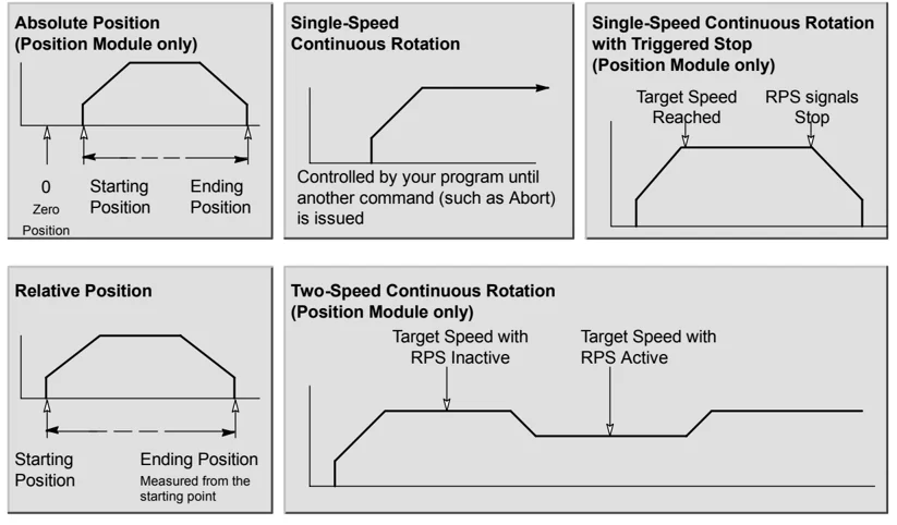
Figure 9-6 Mode Selections for the Position Module
257
Creating the Steps for the Profile
A step is a fixed distance that a tool moves, including the distance covered during acceleration and deceleration times. In the case of the PTO a maximum of 29 steps are allowed in each profile. The module supports a maximum of 4 steps in each profile.
You specify the target speed and ending position or number of pulses for each step. Additional steps are entered one at a time. Figure 9-7 illustrates a one-step, two-step, three-step and a four-step profile.
Notice that a one-step profile has one constant speed segment, a two-step profile has two constant speed segments, and so on. The number of steps in the profile matches the number of constant speed segments of the profile.
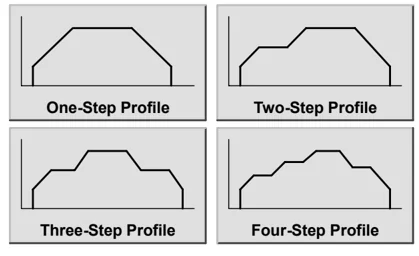
Figure 9-7 Sample Motion Profiles
Using the PTO Output
PTO provides a square wave output (50% duty cycle) for a specified number of pulses. The frequency or cycle time of each pulse changes linearly with frequency during acceleration and deceleration and remains fixed during the constant frequency portions of a movement. Once the specified number of pulses have been generated, the PTO output turns off and no further pulses are generated until a new specification is loaded. See Figure 9-8.
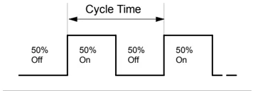
Figure 9-8 Pulse Train Output (PTO)
258
Configuring the PTO Output
To configure one of the built in outputs for PTO operation use the Position Control wizard. To start the Position Control wizard, either click the Tools icon in the navigation bar and then double-click the Position Control Wizard icon, or select the Tools> Position Control Wizard menu command.
- Select the option to configure the onboard PTO/PWM operation for the S7-200 PLC.
- Choose the output Q0.0 or Q0.1 that you wish to configure as a PTO output.
- Select Linear Pulse Train Output (PTO) from the drop down dialog box.
- If you wish to monitor the number of pulses generated by the PTO, select the use High Speed Counter by clicking the check box.
- Enter the MAX_SPEED and the SS_SPEED in the designated edit boxes.
- Enter the acceleration and deceleration times in the designated edit boxes.
- In the motion profile definition screen, click the new profile button to enable defining the profile. Choose the desired mode of operation.
For a relative position profile: Fill in the target speed and the number of pulses. You may then click the plot step button to see a graphical representation of the move. If more than one step is needed, click the new step button and fill in the step information as required.
For a single speed, continuous rotation: Enter the single speed value in the edit box. If you wish to terminate the single speed, continuous rotation move, click the Program a Subroutine check box and and enter the number of pulses to move after the Stop event.
- Define as many profiles and steps as you need to perform the desired movement
- Then select Finish to complete the wizard.
Instructions Created by the Position Control Wizard
The Position Control wizard makes controlling your built-in PTO easier by creating five unique instruction subroutines. Each position instruction is prefixed with a "PTOx_" where x is the channel number (x=0 for Q0.0, x=1 for Q0.1).
PTOx_CTRL Subroutine
The PTOx_CTRL subroutine (Control) enables and initializes the PTO output for use with a stepper or servo motor. Use this subroutine only once in your program and ensure that it is executed every scan. Always use SM0.0 as the input for the EN input.
The I_STOP (Immediate STOP) input is a Boolean input. When this input is low, the PTO function operates normally. When this input goes high, the PTO terminates the issuance of pulses immediately.
The D_STOP (Decelerated STOP) input is a Boolean input. When this input is low, the PTO function operates normally. When this input goes high, the PTO generates a pulse train that decelerates the motor to a stop.
The Done output is a Boolean output. When the Done bit is set high, it indicates the subroutine has been executed by the CPU.
 When the Done bit is high, the Error byte reports normal completion with no error or with an error code. See Table 9-7 for definitions of the error codes.
The C_Pos parameter contains the current position of the module as the number of pulses if the HSC was enabled in the wizard. Otherwise the current position is always 0.
Table 9-3 Parameters for the PTOx_CTRL Instruction