Sample Programs for the Position Module
The first sample program shows a simple relative move that uses the POSx_CTRL and POSx_GOTO instructions to perform a cut-to-length operation. This program does not require an RP seek mode or a motion profile, and the length can be measured in either pulses or engineering units. Enter the length (VD500) and target speed (VD504). When I0.0 (Start) turns on, the machine starts. When I0.1 (Stop) turns on, the machine finishes the current operation and stops. When I0.2 (E_Stop) turns on, the machine aborts any motion and immediately stops.
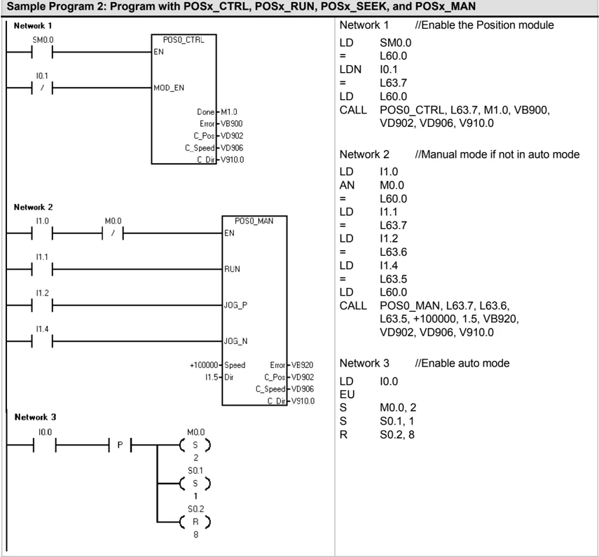
The second sample program provides an example of the POSx_CTRL, POSx_RUN, POSx_RSEEK, and POSx_MAN instructions. You must configure the RP seek mode and a motion profile.
Sample Program 1: Simple Relative Move (Cut to Length application)
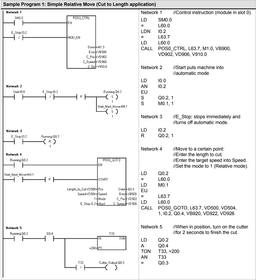
Sample Program 1: Simple Relative Move (Cut to Length application) , continued
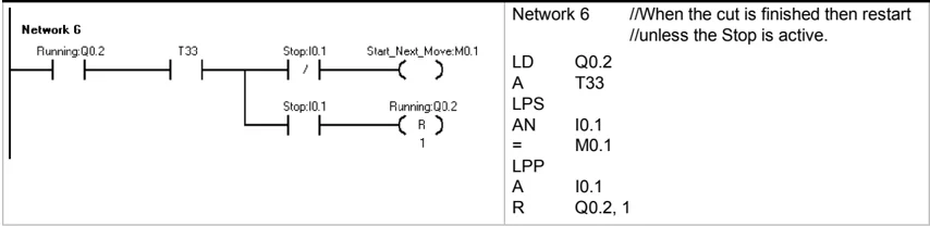
\begin{tabular}{p{0.45\textwidth} p{0.45\textwidth}} \textbf{Network 6} & \textbf{Network 6} //When the cut is finished then restart \ & //unless the Stop is active. \ Running:Q0.2 \quad T33 \quad Stop:I0.1 \quad Start_Next_Move:M0.1 & LD \quad Q0.2 \ & A \quad T33 \ & LPS \ & AN \quad I0.1 \ & = \quad M0.1 \ & LPP \ & A \quad I0.1 \ & R \quad Q0.2, 1 \ \end{tabular}
Sample Program 2: Program with POSx_CTRL, POSx_RUN, POSx_SEEK, and POSx_MAN
286
Open Loop Motion Control with the S7-200 Chapter 9
Sample Program 2: Program with POSx_CTRL, POSx_RUN, POSx_SEEK, and POSx_MAN, continued
| Network 4 | Network 4 //Emergency Stop //Disable the module and auto mode |
|---|---|
| I0.1 | LD I0.1 |
| M0.0 | R M0.0, 1 |
| R | R S0.1, 9 |
| 1 | R Q0.3, 3 |
| S0.1 | |
| R | |
| 9 | |
| Q0.3 | |
| R | |
| 3 | |
| Network 5 | Network 5 //When in auto mode: //Turn on the Running light |
| M0.0 | LD M0.0 |
| Q0.1 | = Q0.1 |
| Network 6 | Network 6 LSCR S0.1 |
| S0.1 | |
| SCR | |
| Network 7 | Network 7 //Find the reference point (RP) |
| S0.1 | LD S0.1 |
| = L60.0 | |
| LD S0.1 | |
| = L63.7 | |
| LD L60.0 | |
| CALL POS0_RSEEK, L63.7, M1.1, VB930 | |
| S0.1 | |
| POS0_RSEEK | |
| EN | |
| START | |
| Done M1.1 | |
| Error VB930 | |
| Network 8 | Network 8 //When at reference point (RP): //Clamp the material and //Go to the next step. |
| M1.1 | LD M1.1 |
| VB930 | LPS |
| ==B | AB= VB930, 0 |
| 0 | S Q0.3, 1 |
| Q0.3 | SCRT S0.2 |
| S | LPP |
| 1 | AB<> VB930, 0 |
| S0.2 | SCRT S1.0 |
| (SCRT) | |
| VB930 | |
| <>B | |
| 0 | |
| S1.0 | |
| (SCRT) | |
| Network 9 | Network 9 SCRE |
| (SCRE) | |
| Network 10 | Network 10 LSCR S0.2 |
| S0.2 | |
| SCR |
287
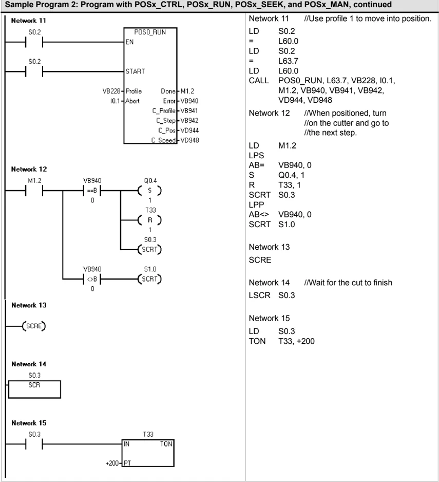
Sample Program 2: Program with POSx_CTRL, POSx_RUN, POSx_SEEK, and POSx_MAN, continued
| Network 11 | Network 11 //Use profile 1 to move into position. |
|---|---|
| LD S 0.2= L60.0LD S 0.2= L63.7LD L60.0CALL POS0_RUN, L63.7, VB228, I0.1,M1.2, VB940, VB941, VB942,VD944, VD948 | |
| Network 12 | Network 12 //When positioned, turn//on the cutter and go to//the next step. |
| LD M1.2LPSAB= VB940, 0S Q0.4, 1R T33, 1SCRT S 0.3LPPAB<> VB940, 0SCRT S 1.0 | |
| Network 13 | Network 13SCRE |
| Network 14 | Network 14 //Wait for the cut to finishLSCR S 0.3 |
| Network 15 | Network 15LD S 0.3TON T33, +200 |
288
Open Loop Motion Control with the S7-200 Chapter 9
Sample Program 2: Program with POSx_CTRL, POSx_RUN, POSx_SEEK, and POSx_MAN, continued
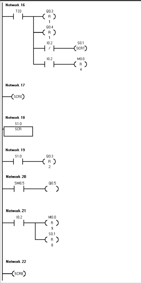
Network 16 //Unless STOP is on, restart //when the cut is finished. LD T33 LPS R Q0.3, 1 R Q0.4, 1 AN I0.2 SCRT S0.1 LPP A I0.2 R M0.0, 4
Network 17 SCRE
Network 18 LSCR S1.0
Network 19 //Reset the outputs. LD S1.0 R Q0.3, 2
Network 20 //Flash the error light. LD SM0.5 = Q0.5
Network 21 //Exit the error routine if STOP is on. LD I0.2 R M0.0, 9 R S0.1, 8
Network 22 SCRE
289
Monitoring the Position Module with the EM 253 Control Panel
To aid you in the development of your Position Control solution, STEP 7-Micro/WIN provides the EM 253 Control Panel. The Operation, Configuration and Diagnostics tabs make it easy for you to monitor and control the operation of the Position module during the startup and test phases of your development process.
Use the EM 253 Control Panel to verify that the Position module is wired correctly, to adjust the configuration data, and to test each movement profile.
Displaying and Controlling the Operation of the Position Module
The Operation tab of the control panel allows you to interact with the operations of the Position Module. The control panel displays the current speed, the current position and the current direction of the Position module. You can also see the status of the input and output LEDs (excluding the Pulse LEDs).
The control panel allows you to interact with the Position module by changing the speed and direction, by stopping and starting the motion, and by jogging the tool (if the motion is stopped).
You can also generate the following motion commands:
Enable Manual Operation. This command allows you to use the manual controls for positioning the tool.
Run a Motion Profile. This command allows you to select a profile to be executed. The control panel displays the status of the profile which is being executed by the Position module.
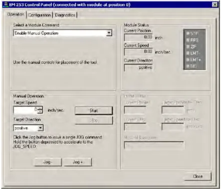
Figure 9-17 Operation Tab of the EM 253 Control Panel
Seek to a Reference Point. This command finds the reference point by using the configured search mode.
Load Reference Point Offset. After you use the manual controls to jog the tool to the new zero position, you then load the Reference Point Offset.
Reload Current Position. This command updates the current position value and establishes a new zero position.
Activate the DIS output and Deactivate the DIS output. These commands turn the DIS output of the Position module on and off.
Pulse the CLR output. This command generates a 50 ms pulse on the CLR output of the Position module.
Teach a Motion Profile. This command allows you to save the target position and speed for a motion profile and step as you manually position the tool. The control panel displays the status of the profile which is being executed by the Position module.
Load Module Configuration. This command loads a new configuration by commanding the Position module to read the configuration block from the V memory of the S7-200.
Open Loop Motion Control with the S7-200 Chapter 9
Move to an Absolute Position. This command allows you to move to a specified position at a target speed. Before using this command, you must have already established the zero position.
Move by a Relative Amount. This command allows you to move a specified distance from the current position at a target speed. You can enter a positive or negative distance.
Reset the Command Interface. This command clears the command byte for the Position module and sets the Done bit. Use this command if the Position module appears to not be responding to commands.
Displaying and Modifying the Configuration of the Position Module
The Configuration tab of the control panel allows you to view and modify the configuration settings for the Position module that are stored in the data block of the S7-200.
After you modify the configuration settings, you simple click a button to update the settings in both the STEP 7-Micro/Win project and the data block of the S7-200.
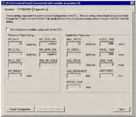
Figure 9-18 Configuration Tab of the EM 253 Control Panel
Displaying the Diagnostics Information for the Position Module
The Diagnostics tab of the control panel allows you to view the diagnostic information about the Position module.
You can view specific information about the Position module, such as the position of the module in the I/O chain, the module type and firmware version number, and the output byte used as the command byte for the module.
The control panel displays any error condition that resulted from a commanded operation. Refer to Table 9-20 for the instruction error conditions.
You can also view any error condition reported by the Position module. Refer to Table 9-21 for the module error conditions.
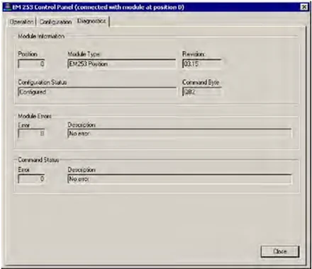
Figure 9-19 Diagnostics Tab of the EM 253 Control Panel
291
Error Codes for the Position Module and the Position Instructions
Table 9-20 Instruction Error Codes
Open Loop Motion Control with the S7-200 Chapter 9
Table 9-21 Module Error Codes
| Error Code | Description |
|---|---|
| 0 | No error |
| 1 | No user power |
| 2 | Configuration block not present |
| 3 | Configuration block pointer error |
| 4 | Size of configuration block exceeds available V memory |
| 5 | Illegal configuration block format |
| 6 | Too many profiles specified |
| 7 | Illegal STP_RSP specification |
| 8 | Illegal LMT-_RPS specification |
| 9 | Illegal LMT+_RPS specification |
| 10 | Illegal FILTER_TIME specification |
| 11 | Illegal MEAS_SYS specification |
| 12 | Illegal RP_CFG specification |
| 13 | Illegal PLS/REV value |
| 14 | Illegal UNITS/REV value |
| 15 | Illegal RP_ZP_CNT value |
| 16 | Illegal JOG_INCREMENT value |
| 17 | Illegal MAX_SPEED value |
| 18 | Illegal SS_SPD value |
| 19 | Illegal RP_FAST value |
| 20 | Illegal RP_SLOW value |
| 21 | Illegal JOG_SPEED value |
| 22 | Illegal ACCEL_TIME value |
| 23 | Illegal DECEL_TIME value |
| 24 | Illegal JERK_TIME value |
| 25 | Illegal BKLSH_COMP value |
293
Advanced Topics
Understanding the Configuration/Profile Table
The Position Control wizard has been developed to make motion applications easy by automatically generating the configuration and profile information based upon the answers you give about your position control system. Configuration/profile table information is provided for advanced users who want to create their own position control routines.
The configuration/profile table is located in the V memory area of the S7-200. As shown in Table 9-22, the configuration settings are stored in the following types of information:
☐ The configuration block contains information used to set up the module in preparation for executing motion commands.
☐ The interactive block supports direct setup of motion parameters by the user program.
☐ Each profile block describes a predefined move operation to be performed by the Position module. You can configure up 25 profile blocks.
Tip To create more than 25 motion profiles, you can exchange configuration/profile tables by changing the value stored in the configuration/profile table pointer.
Table 9-22 Configuration/Profile Table
Table 9-22 Configuration/Profile Table, continued
| Offset | Name | Function Description | Type |
|---|---|---|---|
| 14 | STP_RSP | Specifies the response of the drive to the STP input (1 byte)0 No action. Ignore the input condition.1 Decelerate to a stop and indicate that the STP input is active.2 Terminate the pulses and indicate STP input3 to 255 Reserved (error if specified) | -- |
| 15 | LMT-_RSP | Specifies the response of the drive to the negative limit input (1 byte)0 No action. Ignore the input condition.1 Decelerate to a stop and indicate that the limit has been reached.2 Terminate the pulses and indicate that the limit has been reached.3 to 255 Reserved (error if specified) | -- |
| 16 | LMT+_RSP | Specifies the response of the drive to the positive limit input (1 byte)0 No action. Ignore the input condition.1 Decelerate to a stop and indicate that the limit has been reached.2 Terminate pulses and indicate that the limit has been reached.3 to 255 Reserved (error if specified) | -- |
| 17 | FILTER_TIME | Specifies the filter time for the STP, LMT-, LMT+, and RPS inputs (1 byte)MSB 7 6 5 4 3 2 1 0 LSB'0000' 200 \musec '0101' 3200 \musec'0001' 400 \musec '0110' 6400 \musec'0010' 800 \musec '0111' 12800 \musec'0011' 1600 \musec '1000' No filter'0100' 1600 \musec '1001' to '1111' Reserved (error if specified) | -- |
| 18 | MEAS_SYS | Specifies the measurement system (1 byte)0 Pulses (speed is measured in pulses/second, and the position values are measured in pulses). Values are stored as DINT.1 Engineering units (speed is measured in units/second, and the position values are measured in units). Values are stored as single-precision REAL.2 to 255 Reserved (error if specified) | -- |
| 19 | -- | Reserved (Set to 0) | -- |
| 20 | PLS/REV | Specifies the number of pulses per revolution of the motor (4 bytes)Only applicable when MEAS_SYS is set to 1. | DINT |
| 24 | UNITS/REV | Specifies the engineering units per revolution of the motor (4 bytes)Only applicable when MEAS_SYS is set to 1. | REAL |
| 28 | UNITS | Reserved for STEP 7-Micro/WIN to store a custom units string (4 bytes) | -- |
| 32 | RP_CFG | Specifies the reference point search configuration (1 byte)MSB 7 6 5 4 3 2 1 0 LSBRP_ADDR_DIRRP_SEEK_DIRRP_SEEK_DIR This bit specifies the starting direction for a reference point search.(0 - positive direction, 1 - negative direction)RP_APPR_DIR This bit specifies the approach direction for terminating the reference point search.(0 - positive direction, 1 - negative direction)MODE Specifies the reference point search method.'0000' Reference point search disabled.'0001' The reference point is where the RPS input goes active.'0010' The reference point is centered within the active region of the RPS input.'0011' The reference point is outside the active region of the RPS input.'0100' The reference point is within the active region of the RPS input.'0101' to '1111' Reserved (error if selected) | -- |
| 33 | -- | Reserved (Set to 0) | -- |
| 34 | RP_Z_CNT | Number of pulses of the ZP input used to define the reference point (4 bytes) | DINT |
| 38 | RP_FAST | Fast speed for the RP seek operation: MAX_SPD or less (4 bytes) | DINT REAL |
Table 9-22 Configuration/Profile Table, continued
Open Loop Motion Control with the S7-200 Chapter 9
Table 9-22 Configuration/Profile Table, continued
Special Memory Locations for the Position Module
The S7-200 allocates 50 bytes of special memory (SM) to each intelligent module, based on the physical position of the module in the I/O system. See Table 9-23. When the module detects an error condition or a change in status of the data, the module updates these SM locations. The first module updates SMB200 through SMB249 as required to report the error condition, the second module updates SMB250 through SMB299, and so on.
Table 9-23 Special Memory Bytes SMB200 to SMB549
| SM Bytes for an intelligent module in: | Slot 0 | Slot 1 | Slot 2 | Slot 3 | Slot 4 | Slot 5 | Slot 6 |
|---|---|---|---|---|---|---|---|
| SMB200 to SMB249 | SMB250 to SMB299 | SMB300 to SMB349 | SMB350 to SMB399 | SMB400 to SMB449 | SMB450 to SMB499 | SMB500 to SMB549 |
Table 9-24 shows the structure of the SM data area allocated for an intelligent module. The definition is given as if this were the intelligent module is located in slot 0 of the I/O system.
Table 9-24 Special Memory Area Definition for the EM 253 Position Module
| SM Address | Description |
|---|---|
| SMB200 to SMB215 | Module name (16 ASCII characters). SMB200 is the first character: “EM253 Position” |
| SMB216 to SMB219 | Software revision number (4 ASCII characters). SMB216 is the first character. |
| SMW220 | Error code for the module. See Table 9-21 for a description of the error codes. |
| SMB222 | Input/output status. Reflects the status of the inputs and outputs of the module.DIS Disable outputsSTP Stop inputLMT- Negative travel limit inputLMT+ Positive travel limit inputRPS Reference point switch inputZP Zero pulse inputMSB LSB7 6 5 4 3 2 1 0DIS 0 0 STP LMT- LMT+ RPS ZP0 = No current flow 1 = Current flow0 = No current flow 1 = Current flow0 = No current flow 1 = Current flow0 = No current flow 1 = Current flow0 = No current flow 1 = Current flow0 = No current flow 1 = Current flow |
| SMB223 | Instantaneous module status. Reflects the status of the module configuration and rotation direction status.OR Target speed out of rangeR Direction of rotationCFG Module configuredMSB LSB7 6 5 4 3 2 1 00 0 0 0 0 OR R CFG0 = In range 1 = Out of range0 = Positive rotation 1 = Negative rotation0 = Not configured 1 = Configured |
| SMB224 | CUR_PF is a byte that indicates the profile currently being executed. |
| SMB225 | CUR_STP is a byte that indicates the step currently being executed in the profile. |
| SMD226 | CUR_POS is a double-word value that indicates the current position of the module. |
| SMD230 | CUR_SPD is a double-word value that indicates the current speed of the module. |
| SMB234 | Result of the instruction. See Table 9-20 for descriptions of the error codes. Error conditions above 127 are generated by the instruction subroutines created by the wizard.D Done bit 0= Operation in progress1= Operation complete (set by the module during initialization)MSB LSB7 6 0D ERROR |
| SMB235 to SMB244 | Reserved |
| SMB245 | Offset to the first Q byte used as the command interface to this module. The offset is supplied by the S7-200 automatically for the convenience of the user and is not needed by the module. |
| SMD246 | Pointer to the V memory location of the configuration/profile table. A pointer value to an area other than V memory is not valid. The Position module monitors this location until it receives a non-zero pointer value. |
Understanding the Command Byte for the Position Module
The Position module provides one byte of discrete outputs which is used as the command byte. Figure 9-20 shows the command byte definition. Table 9-20 shows the Command_code definitions.
A write to the command byte where the R bit changes from 0 to 1 is interpreted by the module as a new command.
If the module detects a transition to idle (R bit changes state to 0) while a command is active, then the operation in progress is aborted and, if a motion is in progress, then a decelerated stop is performed.
After an operation has completed, the module must see a transition to idle before a new command is accepted. If an operation is aborted, then the module must complete any deceleration before a new command is accepted. Any change in the Command_code value while a command is active is ignored.
The response of the Position module to a change in the operating mode of the S7-200 or to a fault condition is governed by the effect that the S7-200 exerts over the discrete outputs according to the existing definition of the S7-200 function:
- If the S7-200 changes from STOP to RUN: The program in the S7-200 controls the operation of the Position module.
- If the S7-200 changes from RUN to STOP: You can select the state that the discrete outputs are to go to on a transition to STOP or that the outputs are to retain their last state.
- If the R bit is turned off when going to STOP: The Position module decelerates any motion in progress to a stop
- If the R bit is turned on when going to STOP: The Position module completes any command that is in progress. If no command is in progress, the Position module executes the command which is specified by the Command_code bits.
- If the R bit is held in its last state: The Position module completes any motion in progress.
- If the S7-200 detects a fatal error and turns off all discrete outputs: The Position module decelerates any motion in progress to a stop.
The Position module implements a watchdog timer that turns the outputs off if communications with the S7-200 are lost. If the output watchdog timer expires, the Position module decelerates any motion in progress to a stop.
If a fatal error in the hardware or firmware of the module is detected, the Position module sets the P0, P1, DIS and CLR outputs to the inactive state.
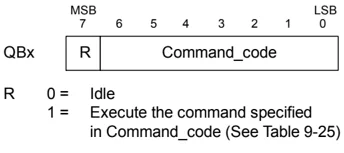
Figure 9-20 Definition of the Command Byte
Table 9-25 Command_code Definitions
| Command_code | Command | Command |
|---|---|---|
| 000 0000 to 000 1111 | 0 to 24 | Execute motion specified in Profile Blocks 0 to 24 |
| 100 0000 to 111 0101 | 25 to 117 | Reserved (Error if specified) |
| 111 0110 | 118 | Activate the DIS output |
| 111 0111 | 119 | Deactivate the DIS output |
| 111 1000 | 120 | Pulse the CLR output |
| 111 1001 | 121 | Reload current position |
| 111 1010 | 122 | Execute motion specified in the Interactive Block |
| 111 1011 | 123 | Capture reference point offset |
| 111 1100 | 124 | Jog positive rotation |
| 111 1101 | 125 | Jog negative rotation |
| 111 1110 | 126 | Seek to reference point position |
| 111 1111 | 127 | Reload configuration |
Table 9-26 Motion Commands
| Command | Description |
|---|---|
| Commands 0 to 24:Executes the motion specified in profile blocks 0 to 24 | When this command is executed, the Position module performs the motion operation specified in the MODE field of the profile block indicated by the Command_code portion of the command.- In Mode 0 (absolute position), the motion profile block defines from one to four steps with each step containing both the position (POS) and speed (SPEED) that describes the move segment. The POS specification represents an absolute location, which is based on the location designated as reference point. The direction of movement is determined by the relationship between the current position and the position of the first step in the profile. In a multi-step move a reversal of direction of travel is prohibited and results in an error condition being reported.- In Mode 1 (relative position), the motion profile block defines from one to four steps with each step containing both the position (POS) and the speed (SPEED) that describes the move segment. The sign of the position value (POS) determines the direction of the movement. In a multi-step move, a reversal of direction of travel is prohibited and results in the reporting of an error condition.- In Modes 2 and 3 (single-speed, continuous operation modes), the position (POS) specification is ignored and the module accelerates to the speed specified in the SPEED field of the first step. Mode 2 is used for positive rotation, and Mode 3 is used for negative rotation. Movement stops when the command byte transitions to Idle.- In Modes 6 and 7 (single-speed, continuous operation modes with triggered stop), the module accelerates to the speed specified in the SPEED field of the first step. If and when the RPS input becomes active, movement stops after completing the distance specified in the POS field of the first step. (The distance specified in the POS field must include the deceleration distance.) If the POS field is zero when the RPS input becomes active, the Position module decelerates to a stop. Mode 6 is used for positive rotation, and Mode 7 is used for negative rotation.- In Modes 8 and 9, the binary value of the RPS input selects one of two speed values as specified by the first two steps in the profile block. - If the RPS is inactive: Step 0 controls the speed of the drive. - If the RPS is active: Step 1 controls the speed of the drive.Mode 8 is used for positive rotation, and Mode 9 is used for negative rotation. The SPEED value controls the speed of movement. The POS values are ignored in this mode. |
| Command 118Activates the DIS output | When this command is executed, the Position module activates the DIS output. |
| Command 119Deactivates the DIS output | When this command is executed, the Position module deactivates the DIS output. |
| Command 120Pulses the CLR output | When this command is executed, the Position module generates a 50-millisecond pulse on the CLR output. |
| Command 121Reloads the Current Position | When this command is executed, the Position module sets the current position to the value found in the TARGET_POS field of the interactive block. |
300
Open Loop Motion Control with the S7-200 Chapter 9
Table 9-26 Motion Commands, continued
| Command | Description |
|---|---|
| Command 122Execute the motion specified inthe interactive block | When this command is executed, the Position module performs the motionoperation specified in the MOVE_CMD field of the interactive block.• In Modes 0 and 1 (absolute and relative motion modes), a single step motion isperformed based upon the target speed and position information provided in theTARGET_SPEED and TARGET_POS fields of the interactive block.• In Modes 2 and 3 (single-speed, continuous operation modes), the positionspecification is ignored, and the Position module accelerates to the speedspecified in the TARGET_SPEED field of the interactive block. Movement stopswhen the command byte transitions to Idle.• In Modes 4 and 5 (manual speed control modes), the position specification isignored and your program loads the value of speed changes into theTARGET_SPEED field of the interactive block. The Position modulecontinuously monitors this location and responds appropriately when the speedvalue changes. |
| Command 123Capture the Reference Pointoffset | When this command is executed, the Position module establishes a zero positionthat is at a different location from the reference point position.Before issuing this command, you must have determined the position of thereference point and must also have jogged the machine to the work startingposition. After receiving this command, the Position module computes the offsetbetween the work starting position (the current position) and the reference pointposition and writes the computed offset to the RP_OFFSET field of the InteractiveBlock. The current position is then set to 0 to establish the work starting position asthe zero position.In the event that the stepper motor loses track of its position (for example, if poweris lost or the stepper motor is repositioned manually) the Seek to Reference PointPosition command can be issued to re-establish the zero position automatically. |
| Command 124Jog positive rotation | This command allows you to manually issue pulses for moving the stepper motor inthe positive direction.If the command remains active for less than 0.5 seconds, the Position moduleissues pulses to travel the distance specified in JOG_INCREMENT.If the command remains active for 0.5 seconds or longer, the motion module beginsto accelerate to the specified JOG_SPEED.When a transition to idle is detected, the Position module decelerates to a stop. |
| Command 125Jog negative rotation | This command allows you to manually issue pulses for moving the stepper motor inthe negative direction.If the command remains active for less than 0.5 seconds, the Position moduleissues pulses to travel the distance specified in JOG_INCREMENT.If the command remains active for 0.5 seconds or longer, the Position modulebegins to accelerate to the specified JOG_SPEED.When a transition to idle is detected, the Position module decelerates to a stop. |
| Command 126Seek to Reference Point position | When this command is executed, the Position module initiates a reference pointseek operation using the specified search method. When the reference point hasbeen located and motion has stopped, the Position module loads the value readfrom the RP_OFFSET field of the interactive block into the current position andpulses the CLR output on for 50 milliseconds. |
| Command 127Reload the configuration | When this command is executed, the Position module reads the configuration/profiletable pointer from the appropriate location in SM memory and then reads theconfiguration block from the location specified by the configuration/profile tablepointer. The Position module compares the configuration data just obtained againstthe existing module configuration and performs any required setup changes orrecalculations. Any cached profiles are discarded. |
301
Understanding the Profile Cache of the Position Module
The Position module stores the execution data for up to 4 profiles in cache memory. When the Position module receives a command to execute a profile, it checks to see if the requested profile is stored in the cache memory. If the execution data for the profile is resident in the cache, the Position module immediately executes the profile. If the the execution data for the profile is not resident in the cache, the Position module reads the profile block information from the configuration/profile table in the S7-200 and calculates the execution data for the profile before executing the profile.
Command 122 (Execute the motion specified in the interactive block ) does not use cache memory to store the execution data, but always reads the interactive block from the configuration/profile table in the S7-200 and calculates the execution data for the motion.
Reconfiguring the Position module deletes all of the execution data stored in the cache memory.
Creating Your Own Position Control Instructions
The Position Control wizard creates the position instructions for controlling the operation of the Position module; however, you can also create your own instructions. The following STL code segment provides an example of how you might create your own control instructions for the Position module.
This example uses an S7-200 CPU 224 with a Position module located in slot 0. The Position module is configured on power-up. CMD_STAT is a symbol for SMB234, CMD is a symbol for QB2, and NEW_CMD is a symbol for the profile.
Sample Program: Controlling the Position Module Network 1 //New move command state LSCR State_0
Network 2 //CMD_STAT is a symbol for SMB234 //CMD is a symbol for QB2 //NEW_CMD is a symbol for the profile. // //1. Clear the Done bit of the Position module. //2. Clear the command byte of the Position module. //3. Issue the new command. //4. Wait for the command to be executed. LD SM0.0 MOVB 0, CMD_STAT BIW 0, CMD BIW NEW_CMD, CMD SCRT State_1
Network 3 SCRE
Network 4 //Wait for the command to be completed. LSCR State_1
Network 5 //If the command is complete without error, go to the idle state. LDB= CMD_STAT, 16#80 SCRT Idle_State
Network 6 //If the command is complete with an error, go to the error handling state. LDB> CMD_STAT, 16#80 SCRT Error_State
Network 7 SCRE
302
Understanding the RP Seek Modes Supported by the Position Module
The following figures provide diagrams of the different options for each RP seek mode.
☐ Figure 9-21 shows two of the options for RP seek mode 1. This mode locates the RP where the RPS input goes active on the approach from the work zone side.
☐ Figure 9-22 shows two of the options for RP seek mode 2. This mode locates the RP in the center within the active region of the RPS input.
☐ Figure 9-23 shows two of the options for RP seek mode 3. This mode locates the RP a specified number of zero pulses (ZP) outside the active region of the RPS input.
☐ Figure 9-24 shows two of the options for RP seek mode 4. This mode locates the RP a specified number of zero pulses (ZP) within the active region of the RPS input.
For each mode, there are four combinations of RP Seek direction and RP Approach direction. (Only two of the combinations are shown.) These combinations determine the pattern for the RP seek operation. For each of the combinations, there are also four different starting points:
The work zones for each diagram have been located so that moving from the reference point to the work zone requires movement in the same direction as the RP Approach Direction. By selecting the location of the work zone in this way, all the backlash of the mechanical gearing system is removed for the first move to the work zone after a reference point seek.
 Figure 9-21 RP Seek Mode 1
Default configuration : RP Seek Direction: Negative RP Approach Direction: Positive
LMT- Active
RPS Active RP
Work Zone
Positive motion Negative motion
 RP Seek Direction: Positive
RP Approach Direction: Positive
RPS Active RP
Work Zone
LMT+ Active
Positive motion Negative motion
Figure 9-22 RP Seek: Mode 2
Default configuration : RP Seek Direction: Negative RP Approach Direction: Positive
LMT- Active
RPS Active RP
Work Zone Number of ZP pulses
Positive motion Negative motion
 RP Seek Direction: Positive
RP Approach Direction: Positive
RPS Active RP
Work Zone Number of ZP pulses
LMT+ Active
Positive motion Negative motion
Figure 9-23 RP Seek: Mode 3
304
Open Loop Motion Control with the S7-200 Chapter 9
 Default configuration :
RP Seek Direction: Negative
RP Approach Direction: Positive
LMT - Active RPS Active RP Work Zone Number of ZP pulses Positive motion Negative motion
RP Seek Direction: Positive RP Approach Direction: Positive
RPS Active RP Work Zone Number of ZP pulses LMT+ Active Positive motion Negative motion
Figure 9-24 RP Seek: Mode 4
305
Selecting the Location of the Work Zone to Eliminate Backlash
Figure 9-25 shows the work zone in relationship to the reference point (RP), the RPS Active zone, and the limit switches (LMT+ and LMT-) for an approach direction that eliminates the backlash. The second part of the illustration places the work zone so that the backlash is not eliminated. Figure 9-25 shows RP seek mode 3. A similar placement of the work zone is possible, although not recommended, for each of the search sequences for each of the other RP seek modes.
 Figure 9-25 Placement of the Work Zone with and without the Elimination of Backlash
306
Creating a Program for the Modem Module
The EM 241 Modem module allows you to connect your S7-200 directly to an analog telephone line, and supports communications between your S7-200 and STEP 7-Micro/WIN. The Modem module also supports the Modbus slave RTU protocol. Communications between the Modem module and the S7-200 are made over the Expansion I/O bus.
STEP 7-Micro/WIN provides a Modem Expansion wizard to help set up a remote modem or a Modem module for connecting a local S7-200 to a remote device.
I n This Chapter
- Features of the Modem Module . . . . . . . . . . . . . . . . . . . . . . . . . . . . . . . . . . . . . . . . . . . . . . . . . . . . . . . . . . . . . . . . . . . . . . . . . . . . . . . . . . . . . . . . . . . . . . . . . . ........ 308
- Using the Modem Expansion Wizard to Configure the Modem Module . . . . . . . . . . . . . . . . . . . . . . . . . . . . . . . . . . . . . . . . . . . . . . . . . . . . . . . . . . . . . . . . . . . . . . . . . . . . . . . . . . . . . . . . . . . . . . . . . . . . . . . . . . . . . . . . . . . . . . . . . . . . . . . . . . . . . . . . . . . . . . . . . . . . . . . . . . . . . . . . . . . . . . . . . . . . . . . . . . . . . . . . . . . . . . . . . . . . . . . . . . . . . . . . . . . . . . . . . . . ........ 314
- Overview of Modem Instructions and Restrictions . . . . . . . . . . . . . . . . . . . . . . . . . . . . . . . . . . . . . . . . . . . . . . . . . . . . . . . . . . . . . . . . . . . . . . . . . . . . . . . . . . . . . . . . . . . . . . . . ........

Features of the Modem Module
The Modem module allows you to connect your S7-200 directly to an analog telephone line and provides the following features:
Provides international telephone line interface
Provides a modem interface to STEP 7-Micro/WIN for programming and troubleshooting (teleservice)
Supports the Modbus RTU protocol
Supports numeric and text paging
Supports SMS messaging
Allows CPU-to-CPU or CPU-to Modbus data transfers
Provides password protection
Provides security callback
The Modem module configuration is stored in the CPU
 Figure 10-1 EM 241 Modem Module
You can use the STEP 7-Micro/WIN Modem Expansion wizard to configure the Modem module. Refer to Appendix A for the specifications of the Modem module.
International Telephone Line Interface
The Modem module is a standard V.34 (33.6 kBaud), 10-bit modem, and is compatible with most internal and external PC modems. The Modem module does not communicate with 11-bit modems.
You connect the Modem module to the telephone line with the six-position four-wire RJ 11 connector mounted on the front of the module. See Figure 10-2.
An adapter may be required to convert the RJ 11 connector for connection to the standard telephone line termination in the various countries. Refer to the documentation for your adapter connector for more information.
The modem and telephone line interface is powered from an external 24 VDC supply. This can be connected to the CPU sensor supply or to an external source. Connect the ground terminal on the Modem module to the system earth ground.
The Modem module automatically configures the telephone interface for country-specific operation when power is applied to the module. The two rotary switches on the front of the module select the country code. You must set the switches to the desired country selection before the Modem module is powered up. Refer to Table 10-1 for switch settings for the countries supported.
Figure 10-2 View of RJ 11 Jack
Table 10-1 Countries Supported by the EM 241
\begin{tabular}{ll} \hline Switch Setting & Country \ \hline 00 & Australia \ 01 & Austria \ 02 & Belgium \ 05 & Canada \ 06 & China \ 08 & Denmark \ 09 & Finland \ 10 & France \ 11 & Germany \ 12 & Greece \ 16 & Ireland \ 18 & Italy \ 22 & Luxembourg \ 25 & Netherlands \ 26 & New Zealand \ 27 & Norway \ 30 & Portugal \ 34 & Spain \ 35 & Sweden \ 36 & Switzerland \ 38 & U.K. \ 39 & U.S.A. \ \hline \end{tabular}

Creating a Program for the Modem Module Chapter 10
STEP 7-Micro/WIN Interface
The Modem module allows you to communicate with STEP 7-Micro/WIN over a telephone line (teleservice). You do not need to configure or program the S7-200 CPU to use the Modem module as the remote modem when used with STEP 7-Micro/WIN.
Follow these steps to use the Modem module with STEP 7-Micro/WIN:
- Remove the power from the S7-200 CPU and attach the Modem module to the I/O expansion bus. Do not attach any I/O modules while the S7-200 CPU is powered up.
- Connect the telephone line to the Modem module. Use an adapter if necessary.
- Connect 24 volts DC to the Modem module terminal blocks.
- Connect the Modem module terminal block ground connection to the system ground.
- Set the country code switches.
- Power up the S7-200 CPU and the Modem module.
- Configure STEP 7-Micro/WIN to communicate to a 10-bit modem.
Modbus RTU Protocol
You can configure the Modem module to respond as a Modbus RTU slave. The Modem module receives Modbus requests over the modem interface, interprets those requests and transfers data to or from the CPU. The Modem module then generates a Modbus response and transmits it out over the modem interface.
Tip
If the Modem module is configured to respond as a Modbus RTU slave, STEP 7-Micro/WIN is not able to communicate to the Modem module over the telephone line.
The Modem module supports the Modbus functions shown in Table 10-2.
Modbus functions 4 and 16 allow reading or writing a maximum of 125 holding registers (250 bytes of V memory) in one request. Functions 5 and 15 write to the output image register of the CPU. These values can be overwritten by user program.
Modbus addresses are normally written as 5 or 6 character values containing the data type and the offset. The first one or two characters determine the data type, and the last four characters select the proper value within the data type. The Modbus master device maps the addresses to the correct Modbus functions.
Table 10-2 Modbus Functions Supported by Modem Module
| Function | Description |
|---|---|
| Function 01 | Read coil (output) status |
| Function 02 | Read input status |
| Function 03 | Read holding registers |
| Function 04 | Read input (analog input) registers |
| Function 05 | Write single coil (output) |
| Function 06 | Preset single register |
| Function 15 | Write multiple coils (outputs) |
| Function 16 | Preset multiple registers |
309