Table 12-11 Modbus Master MBUS_MSG Execution Error Codes, continued
Program Example
This example program shows how to use the Modbus Master instructions to write and then read 4 holding registers to and from a Modbus slave each time input I0.0 is turned on.
The S7-200 CPU will write 4 words starting at VW100 to the Modbus slave. The data will be written to 4 holding registers in the slave starting at address 40001.
The S7-200 CPU will then read 4 holding registers from the Modbus slave. The data will come from holding registers 40010 - 40013 and be placed into the V-memory of the S7-200 CPU starting at VW200.
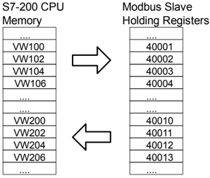
Figure 12-3 Example Program Data Transfers
Example of Programming the Modbus Master Protocol
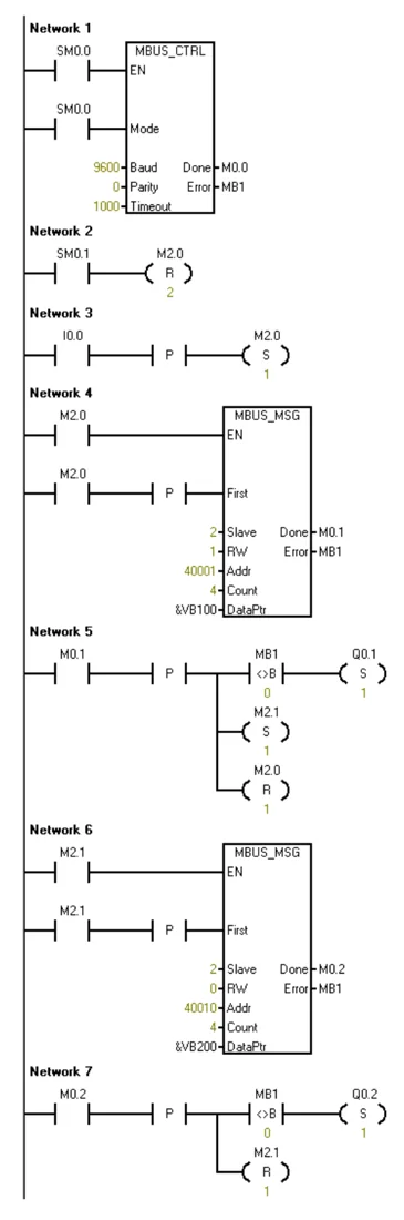
The program will turn on outputs Q0.1 and Q0.2 if there is an error returned from the MBUS_MSG instruction.
Network 1
// Initialize and monitor the Modbus // Master by calling MBUS_CTRL on // every scan. // The Modbus Master is set for 9600 baud // and no parity. The slave is allowed 1000 // milliseconds (1 second) to respond.
Network 2
// On the first scan, reset the enable flags // (M2.0 and M2.1) used for the two // MBUS_MSG instructions.
Network 3
// When I0.0 changes from OFF to ON, set // the enable flag for the first MBUS_MSG // instruction (M2.0).
Network 4
// Call the MBUS_MSG instruction when the // first enable flag (M2.0) is ON. The First // parameter must be set for only the first // scan that the instruction is enabled. // This instruction writes (RW = 1) 4 holding // registers to slave 2. The write data is taken // from VB100 VB107 (4 words) in the CPU // and written to address 40001 - 40004 in // the Modbus slave.
Network 5
// When the first MBUS_MSG instruction is // complete (Done goes from 0 to 1), clear // the enable for the first MBUS_MSG and set // the enable for the second MBUS_MSG // instruction. // If Error (MB1) is not zero then set Q0.1 to // show the error.
Network 6
// Call the second MBUS_MSG instruction // when the second enable flag (M2.1) is ON. // The First parameter must be set for only // the first scan that the instruction is // enabled. // This instruction reads (RW = 0) 4 holding // registers from slave 2. The data is read // from address 40010 - 40013 in the Modbus // slave and copied to VB200 - VB207 // (4 words) in the CPU.
Network 7
// When the second MBUS_MSG instruction // is complete (Done goes from 0 to 1), clear // the enable for the second MBUS_MSG // instruction. // If Error (MB1) is not zero then set Q0.2 to // show the error.
Advanced Topics
This topic contains information for advanced users of the Modbus Master Protocol Library. Most users of the Modbus Master Protocol Library should not need this information and should not modify the default operation of the Modbus Master Protocol Library.
Retries
The Modbus Master instructions will automatically resend the request to the slave device if one of the following errors is detected:
☐ There is no response within the response timeout time (parameter Timeout on the MBUS_CTRL) instruction (Error code 3).
☐ The time between characters of the response exceeded the allowed value (Error code 3).
☐ There is a parity error in the response from the slave (Error code 1).
☐ There is a CRC error in the response from the slave (Error code 8).
☐ The returned function did not match the request (Error code 7).
The Modbus Master will resend the request two additional times before setting the Done and Error output parameters.
The number of retries can be changed by finding the symbol mModbusRetries in the Modbus Master symbol table and changing this value after MBUS_CTRL has been executed. The mModbusRetries value is a BYTE with a range of 0 to 255 retries.
I nter-character timeout
The Modbus Master will abort a response from a slave device if the time between characters in the response exceeds a specified time limit. The default time is set to 100 milliseconds which should allow the Modbus Master Protocol to work with most slave devices over wire or telephone modems. If this error is detected, the MBUS CTRL Error parameter will be set to error code 3.
There may be cases where a longer time between characters is required, either because of the transmission medium (i.e. telephone modem) or because the slave device itself requires more time. This timeout can be lengthened by finding the symbol mModbusCharTimeout in the Modbus Master symbol table and changing this value after MBUS_CTRL has been executed. The mModbusCharTimeout value is an INT with a range of 1 to 30000 milliseconds.
Single vs. Multiple Bit/Word Write Functions
Some Modbus slave devices do not support the Modbus functions to write a single discrete output bit (Modbus function 5) or to write a single holding register (Modbus function 6). These devices only support the multiple bit write (Modbus function 15) or multiple register write (Modbus function 16) instead. The MBUS_MSG instruction will return an error code 101 if the slave device does not support the single bit/word Modbus functions.
The Modbus Master Protocol allows you to force the MBUS_MSG instruction to use the multiple bit/word Modbus functions instead of the single bit/word Modbus functions. You can force the multiple bit/word instructions by finding the symbol mModbusForceMulti in the Modbus Master symbol table and changing this value after MBUS_CTRL has been executed. The mModbusForceMulti value is a data type BOOL value and should be set to a 1 to force the use of the multiple bit/word functions when a single bit/register is written.
Using the Modbus Protocol Library Chapter 12
Accumulator Usage
The accumulators (AC0, AC1, AC2, AC3) are utilized by the Modbus Master instructions and appear in the Cross Reference listing. The values in the accumulators are saved and restored by the Modbus Master instructions. All user data in the accumulators is preserved while executing the Modbus Master instructions.
Holding Registers Addresses Greater Than 9999
Modbus holding addresses are generally within the range of 40001 through 49999. This range is adequate for most applications but there are some Modbus slave devices with data mapped into holding registers with addresses greater than 9999. These devices do not fit the normal Modbus addressing scheme.
The Modbus Master instructions support addressing holding registers greater than 9999 via an alternate addressing method. The MBUS_MSG instruction allows an additional range for the parameter Addr to support an extended range of holding register addresses.
400001 to 465536 for holding registers
For example: to access holding register 16768, the Addr parameter of MBUS_MSG should be set to 416768.
The extended addressing allows access to the full range of 65536 possible addresses supported by the Modbus protocol. This extended addressing is only supported for holding registers.
Using Recipes
13
STEP 7-Micro/Win provides the Recipe Wizard to help you organize recipes and recipe definitions. Recipes are stored in the memory cartridge instead of the PLC.
I n This Chapter
- Overview . . . . . . . . . . . . . . . . . . . . . . . . . . . . . . . . . . . . . . . . . . . . . . . . . . . . . . . . . . . . . . . . . . . . . . . . . . . . . . . . . . . . . . . . . . . . . . . . . . . . . . . . . . . . . . . . . . . . . . . . . . . . . . . . . . . . . . . . ........ 366
- Recipe Definition and Terminology . . . . . . . . . . . . . . . . . . . . . . . . . . . . . . . . . . . . . . . . . . . . . . . . . . . . . . . . . . . . . . . . . . . . . . . . . . . . . . . . . . . . . . . . . . . . . . . . . . . . . . ........ 367
- Using the Recipe Wizard . . . . . . . . . . . . . . . . . . . . . . . . . . . . . . . . . . . . . . . . . . . . . . . . . . . . . . . . . . . . . . . . . . . . . . . . . . . . . . . . . . . . . . . . . . . . . . . . . . . . . . . . . . . . . . . . . . ........

Overview
Support for recipes has been incorporated into STEP 7-Micro/WIN and the S7-200 PLC. STEP 7-Micro/Win provides the Recipe Wizard to help you organize recipes and recipe definitions.
Recipe
All recipes are stored in the memory cartridge. Therefore, to use the recipe feature, an optional 64kB or 256kB memory cartridge must be installed in the PLC. See Appendix A for more information about the memory cartridges.
All recipes are stored in the memory cartridge. However, a single recipe is read into PLC memory when the user program is processing this individual recipe. For example, if you are making cookies, there may be recipes for chocolate chip, sugar, and oatmeal cookies. Only one type of cookie can be made at a time, so the proper recipe must be selected and read into PLC memory.
Figure 13-1 illustrates a process for making multiple types of cookies using recipes. The recipe for each type of cookie is stored in the memory cartridge. Using a TD 200C text display, the operator selects the type of cookie to be made, and the user program loads that recipe into memory.
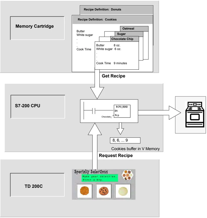
Figure 13-1 Example of Recipe Application
Recipe Definition and Terminology
To help you understand the Recipe Wizard, the following definitions and terms are explained.
A recipe configuration is the set of project components generated by the Recipe Wizard. These components include instruction subroutines, data block tabs, and symbol tables.
A recipe definition is a collection of recipes that have the same set of parameters. However, the values for the parameters can vary depending upon the recipe.
A recipe is the set of parameters and parameter values that provides the information needed to produce a product or control a process.
For example, different recipe definitions can be created, such as donuts and cookies. The cookie recipe definition may contain many different recipes, such as chocolate chip and sugar cookies. Example fields and values are shown in Table 13-1.
Table 13-1 Example of Recipe Definition – Cookies
Using the Recipe Wizard
Use the Recipe Wizard to create recipes and recipe definitions. Recipes are stored in the memory cartridge. Recipes and recipe definitions can be entered directly in the Recipe Wizard. Later changes to individual recipes can be made by running the Recipe Wizard again or by programming with the RCPx_WRITE instruction subroutine.
The Recipe Wizard creates a recipe configuration that includes the following:
A symbol table for each recipe definition. Each table includes symbol names that are the same as the recipe field names. These symbols define the V memory addresses needed to access the recipe values currently loaded in memory. Each table also includes a symbolic constant to reference each recipe.
A data block tab for each recipe definition. This tab defines the initial values for each V memory address represented within the symbol table.
A RCPx_READ instruction subroutine. This instruction is used to read the specified recipe from the memory cartridge to V memory.
A RCPx_WRITE instruction subroutine. This instruction is used to write recipe values from V memory to the memory cartridge.
Defining Recipes
To create a recipe using the Recipe Wizard, select the Tools > Recipe Wizard menu command. The first screen is an introductory screen defining the basic operations of the recipe wizard. Click on the Next button to begin configuring your recipes.
To create a recipe definition, follow the steps below. See Figure 13-2.
- Specify the field names for the recipe definition. Each name will become a symbol in your project as previously defined.
- Select a data type from the drop down list.
- Enter a default value and comment for each name. All new recipes specified within this definition will begin with these default values.
- Click Next to create and edit recipes for this recipe definition
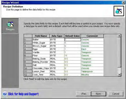
Figure 13-2 Defining Recipes
Use as many rows as necessary to define all data fields in the recipe. You can have up to four different recipe definitions. The number of recipes for each definition is limited only by the available space within the memory cartridge.
Creating and Editing Recipes
The Create and Edit Recipes screen allows you to create individual recipes and specify values for these recipes. Each editable column represents a unique recipe.
Recipes can be created by pressing the New button. Each recipe is initialized with the default values specified during the creation of the recipe definition.
Recipes can also be created from the right mouse context menu by copying and pasting existing recipes. New columns will be inserted to the left of the current cursor position including the comment field.
Each new recipe will be given a default name that includes a reference to the recipe definition and recipe number. This name will be in the form of DEFx_RCPy.
To create and edit recipes, follow the steps below. See Figure 13-3.
- Click on the Next button to get to the Create and Edit Recipe window.
- Select the New button to insert a new recipe as needed.
- Rename the recipe name to an appropriate non-default name.
- Change the values in each recipe data set as needed.
- Click OK.
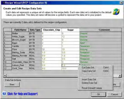
Figure 13-3 Creating and Editing Recipes
Allocating Memory
The Allocate Memory screen specifies the starting address of the V memory area that will store the recipe loaded from the memory cartridge. You can either select the V memory address or let the Recipe wizard to suggest the address of an unused V memory block of the correct size.
To allocate memory, follow the steps below. See Figure 13-4.
- To select the V memory address where you want the recipe to be stored, click in the window and enter the address.
- To let the Recipe Wizard select an unused V memory block of the correct size, click the Suggest Address button.
- Click the Next button.
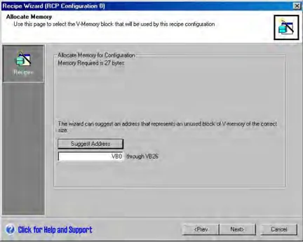
Figure 13-4 Allocating Memory
Project Components
The project components screen lists the different components that will be added to your project. See Figure 13-5.
Click Finish to complete the Recipe Wizard and add these components.
Each recipe configuration can be given a unique name. This name will be shown in the project tree with each wizard configuration. The recipe definition (RCPx) will be appended to the end of this name.
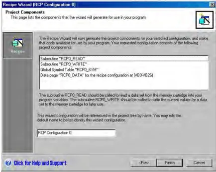
Figure 13-5 Project Components
Using the Symbol Table
A symbol table is created for each recipe definition. Each table defines constant values that represent each recipe. These symbols can be used as parameters for the RCPx_READ and RCPx_WRITE instructions to indicate the desired recipe See Figure 13-6.
Each table also creates symbol names for each field of the recipe. You can use these symbols to access the values of the recipe in V memory.
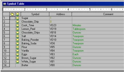
Figure 13-6 Symbol Table
Downloading the Project with a Recipe Configuration
To download a project that contains a recipe configuration, follow the steps below. See Figure 13-7.
- Select File > Download.
- In the dialog, under Options, ensure that the Program Block, Data Block, and Recipes boxes are checked.
- Click the Download button.
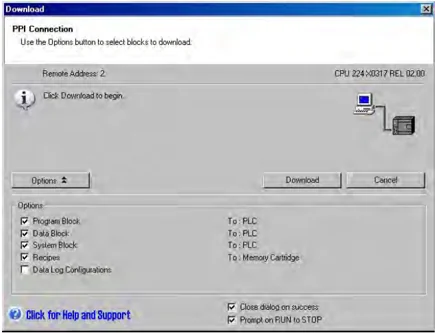
Figure 13-7 Downloading a Project with Recipe Configuration
Edit Existing Recipe Configurations
To edit existing recipe configurations follow the steps below. See Figure 13-8.
- Click on the configuration drop down list and select an existing recipe configuration.
- To delete an existing recipe configuration, click on the Delete Configuration button.
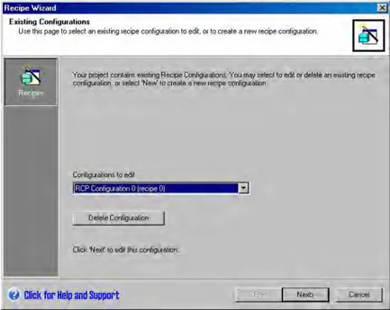
Figure 13-8 Editing Existing Recipe Configurations
Instructions Created by the Recipe Wizard
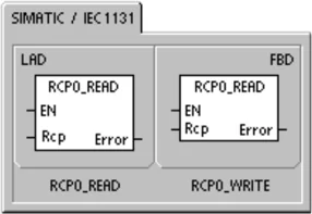
RCPx_Read Subroutine
The Subroutine RCPx_READ is created by the Recipe Wizard and is used to read an individual recipe from the memory cartridge to the specified area in V memory.
The x in the RCPx_READ instruction corresponds to the recipe definition that contains the recipe that you wish to read.
The EN input enables the execution of the instruction when this input is high.
The Rcp input identifies the recipe that will be loaded from the memory cartridge
The Error output returns the result of the execution of this instruction. See Table 13-3 for definitions of the error codes.
RCPx_Write Subroutine
The Subroutine RCPx_WRITE is created by the Recipe Wizard and is used to replace a recipe in the memory cartridge with the contents of the recipe contained in V memory.
The x in the RCPx_WRITE instruction corresponds to the recipe definition that contains the recipe that you wish to replace.
The EN input enables the execution of the instruction when this input is high.
The Rcp input identifies the recipe that will be replaced in the memory cartridge.
The Error output returns the result of the execution of this instruction. See Table 13-3 for definitions of the error codes.
Table 13-2 Valid Operands for the Recipe Subroutine \begin{tabular}{|l|l|l|} \hline Inputs/Outputs & Data Type & Operands \ \hline Rcp & Word & VW, IW, QW, MW, SW, SMW, LW, AC, *VD, *AC, *LD, Constant \ \hline Error & Byte & VB, IB, QB, MB, SB, SMB, LB, AC, *VD, *AC, *LD \ \hline \end{tabular}
Table 13-3 Error Codes for the Recipe Instructions \begin{tabular}{|l|l|} \hline Error Code & Description \ \hline 0 & No error \ \hline 132 & Access to the memory cartridge failed \ \hline \end{tabular}
Tip The EEPROM used in the memory cartridge will support a limited number of write operations. Typically, this is one million write cycles. Once this limit has been reached, the EEPROM will not operate properly.
Make sure that you do not enable the RCPx_WRITE instruction on every scan. Enabling this instruction on every scan will wear out the memory cartridge in a relatively short period of time.
Using Data Logs
STEP 7-Micro/Win provides the Data Log Wizard to store process measurement data in the memory cartridge. Moving process data to the memory cartridge frees V memory addresses that would otherwise be required to store this data.
I n This C hapter
- Overview . . . . . . . . . . . . . . . . . . . . . . . . . . . . . . . . . . . . . . . . . . . . . . . . . . . . . . . . . . . . . . . . . . . . . . . . . . . . . . . . . . . . ........ 374
- Using the Data Log Wizard . . . . . . . . . . . . . . . . . . . . . . . . . . . . . . . . . . . . . . . . . . . . . . . . . . . . . . . . . . . . . . . . . . . . . . . . . . . . . . . . . . . . . . . . . . . . . . . . . . . . . . . . . . ........ 375
- Instruction Created by the Data Log Wizard . . . . . . . . . . . . . . . . . . . . . . . . . . . . . . . . . . . . . . . . . . . . . . . . . . . . . . . . . . . . . . . . . . . . . . . . . . . . . . . . . . . . . . . . . . . . . . . . . . . . . . . . ........

Overview
Support for data logs have been incorporated into STEP 7-Micro/WIN and the S7-200 PLC. With this feature, you can permanently store records containing process data under program control. These records can optionally contain a time and date stamp. You can configure up to four independent data logs. The data log record format is defined using the new Data Log Wizard
All data logs are stored in the memory cartridge. To use the data log feature, you must have installed an optional 64K or 256K memory cartridge in your PLC. See Appendix A for information about the memory cartridges.
You must use the S7-200 Explorer to upload the contents of your data logs to your computer.
An example of a Data Log application is shown in Figure 14-1.
 Figure 14-1 Example of Data Log Application
Data Log Definition and Terminology
To help you understand the Data Log Wizard, the following definitions and terms are explained.
A data log is a set of records usually ordered by date and time. Each record represents some process event that records a set of process data. The organization of this data is defined with the data log wizard.
A data log record is a single row of data written to the data log.
374
Using the Data Log Wizard
Use the Data Log Wizard to configure up to four data logs. The Data Log Wizard is used to:
Define the format of the data log record
Select data log options such as time stamp, date stamp, and clear data log on upload
Specify the maximum number of records that can be stored in the data log
Create project code used to store records in the data log.
The Data Log Wizard creates a data log configuration that includes the following:
A symbol table for each data log configuration. Each table includes symbol names that are the same as the data log field names. Each symbol defines the V memory addresses needed to store the current data log. Each table also includes a symbolic constant to reference each data log.
A data block tab for each data log record that assigns V memory addresses for each data log field. Your program uses these V memory addresses to accumulate the current log data set.
A DATx_WRITE subroutine. This instruction copies the specified data log record from V memory to the memory cartridge. Each execution of DATx_WRITE adds a new data record to the log data stored in the memory cartridge.
Data Log Options
You can configure the following optional behaviors for the data log. See Figure 14-2.
Time Stamp You can include a Time Stamp with each data log record. When selected, the CPU automatically includes a time stamp with each record when the user program commands a data log write.
Date Stamp You can add a Date Stamp to each data log record. When selected, the CPU automatically includes a date stamp with each record when the user program commands a data log write.
Clear Data Log Clear Data Log - You can clear all records from the data log whenever it is uploaded. If you set the Clear Data Log option, the data log will be cleared each time it is uploaded.
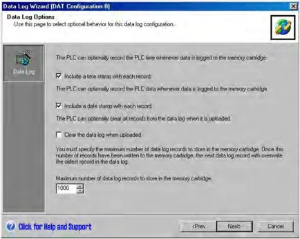
Figure 14-2 Data Log Options
Data logs are implemented as a circular queue (when the log is full, a new record replaces the oldest record). You must specify the maximum number of records to store in the data log. The maximum number of records allowed in a data log is 65,535. The default value for the number of records is 1000.
Defining the Data Log
You specify the fields for the data log and each field becomes a symbol in your project. You must specify a data type for each field. A data log record can contain between 4 and 203 bytes of data. To define the data fields in the data log, follow the steps below. See Figure 14-3.
- Click on the Field Name cell to enter the name. The name becomes the symbol referenced by the user program.
- Click on the Data Type cell and select a data type from the drop down list.
- To enter a comment, click on the Comment cell.
- Use as many rows as necessary to define a record.
- Click OK.
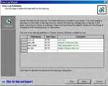
Figure 14-3 Defining the Data Log Record
Edit Existing Data Log Configuration
To edit an existing data log configuration, follow the steps below:
- Click on the configuration dropdown list and select an existing data log configuration as shown in Figure 14-4.
- To delete an existing data log configuration, click on the Delete Configuration button.
You can have up to four different data logs.
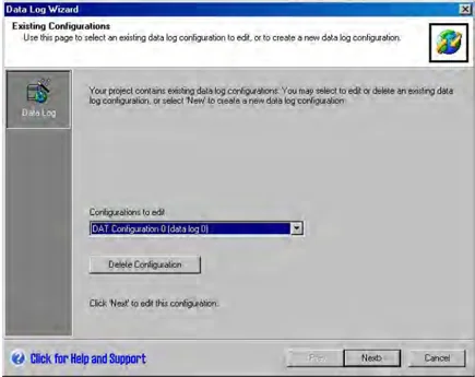
Figure 14-4 Edit Existing Data Log Configurations
376
Allocating Memory
The Data Log Wizard creates a block in the V memory area of the PLC. This block is the memory address where a data log record will be constructed before it is written to the memory cartridge. You specify a starting V memory address where you want the configuration to be placed. You can either select the V memory address or let the Data Log wizard suggest the address of an unused V memory block of the correct size. The size of the block varies based on the specific choices you have made in the Data Log wizard. See Figure 14-5.
To allocate memory, follow the steps below:
- To select the V memory address where the data log record will be constructed, click in the Suggested Address area and enter the address.
- To let the Data Log Wizard select an unused V memory block of the correct size, click the Suggest Address button.
- Click the Next button.
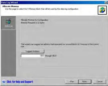
Figure 14-5 Allocating Memory
Project Components
The project components screen lists the different components that will be added to your project. See Figure 14-6.
Click Finish to complete the Data Log Wizard and add these components.
Each data log configuration can be given a unique name. This name will be shown in the project tree with each wizard configuration. The data log definition (DATx) will be appended to the end of this name.
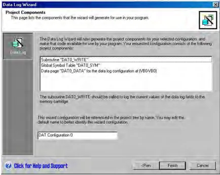
Figure 14-6 Project Components
Using the Symbol Table
A symbol table is created for each data log configuration. Each table defines constant values that represent each data log. These symbols can be used as parameters for the DATx_WRITE instructions.
Each table also creates symbol names for each field of the data log. You can use these symbols to access the values of the data log in V memory.
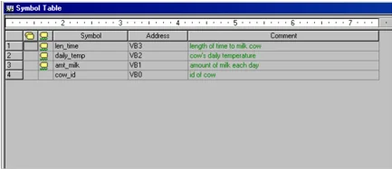
Figure 14-7 Symbol Table
S7-200 Programmable Controller System Manual
Downloading a Project that contains a Data Log Configuration
You must download a project that contains a data log configuration to an S7-200 CPU before the data log can be used. If a project has a data log configuration, then the download window has the Data Log Configurations option checked by default.
Tip When you download a project that contains data log configurations, any data log records currently stored on the memory cartridge will be lost.
To download a project that contains data log configurations, follow the steps below. See Figure 14-8.
- Select File > Download.
- In the dialog, under Options, ensure that the Data Log Configuration box is checked.
- Click the Download button.
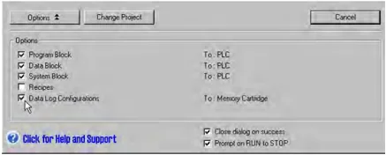
Figure 14-8 Downloading a Project with a Data Log Configuration
Using the S7-200 Explorer
The S7-200 Explorer is the application used to read a data log from the memory cartridge, and then store the data log in a Comma separated Values (CSV) file.
Each time a data log is read, a new file is created. This file is saved in the Data Log directory. The file name is formatted as follows: PLC Address, data log name, date, and time.
You can choose whether the application associated with the CSV extension is automatically launched when the data log has successfully been read. This selection is available from the right mouse menu of the data log file.
The Data Log directory will be below the directory specified during installation. The default installation directory is c:\program files\siemens\Microsystems (if STEP 7 is not installed). The default installation is c:\siemens\Microsystems (if STEP 7 is installed).
To read a data log, follow the steps below:
- Open Windows Explorer. The My S7-200 Network folder should automatically become visible.
- Select the My S7-200 Network folder.
- Select the correct S7-200 PLC folder.
- Select the memory cartridge folder
- Find the correct data log configuration file. These files will be named DAT Configuration x (DATx).
- Select the right mouse context menu, and then select Upload.
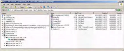
Figure 14-9 Using the S7-200 Explorer
378
Instruction Created by the Data Log Wizard
The Data Log Wizard adds one instruction subroutine to your project.
DATx_WRITE Subroutine
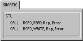
The Subroutine DATx_WRITE is used to log the current values of the data log fields to the memory cartridge. DATxWRITE adds one record to the logged data in the memory cartridge. A call to this subroutine appears as follows.
Error 132 is returned when this instruction fails to correctly access the memory cartridge.
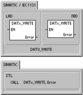
Table 14-1 Parameters for the DATAx_WRITE Subroutine \begin{tabular}{|l|l|l|} \hline Inputs/Outputs & Data Type & Operands \ \hline Error & Byte & VB, IB, QB, MB, SB, SMB, LB, AC, *VD, *AC, *LD \ \hline \end{tabular}
Tip The EEPROM used in the memory cartridge will support a limited number of write operations. Typically, this is one million write cycles. Once this limit has been reached, the EEPROM will not operate properly.
Make sure that you do not enable the DATx_WRITE instruction on every scan. Enabling this instruction on every scan will wear out the memory cartridge in a relatively short period of time.
PID Auto-Tune and the PID Tuning Control Panel
PID Auto-Tune capability has been incorporated into the S7-200 PLCs and STEP 7-Micro/WIN has added a PID Tuning Control Panel. Together, these two features greatly enhance the utility and ease of use of the PID function provided in the S7-200 Micro PLC line.
Auto-tune can be initiated by the user program from an operator panel or by the PID Tuning Control Panel. PID loops can be auto-tuned one at a time or all eight loops can be auto-tuned at the same time if necessary. The PID Auto-Tune computes suggested (near optimum) values for the gain, integral time (reset) and derivative time (rate) tuning values. It also allows you to select tuning for fast, medium, slow or very slow response of your loop.
With the PID Tuning Control Panel you can initiate the auto-tuning process, abort the auto-tuning process and monitor the results in a graphical form. The control panel displays any error conditions or warnings that might be generated. It also allows you to apply the gain, reset and rate values computed by auto-tune.
I n This Chapter
- Understanding the PID Auto-Tune . . . . . . . . . . . . . . . . . . . . . . . . . . . . . . . . . . . . . . . . . . . . . . . . . . . . . . . . . . . . . . . . . . . . . . . . . . . . . . . . . . . . . . . . . . . . . . . . . . . . . . . . . . . . . . . . . . . . . . . . . . . . . . . . . . . . . . . . . . . . . . . . . . . . . . . . . . . . . . . . . . . . . . . . . . . . . . . . . . . . . . . . . . . . . . . . . . ........ 382
- Expanded Loop Table . . . . . . . . . . . . . . . . . . . . . . . . . . . . . . . . . . . . . . . . . . . . . . . . . . . . . . . . . . . . . . . . . . . . . . . . . . . . . . . . . . . . . . . . . . . . . . . . . . . . . . . . . . . . ........ 382
- Prerequisites . . . . . . . . . . . . . . . . . . . . . . . . . . . . . . . . . . . . . . . . . . . . . . . . . . . . . . . . . . . . . . . . . . . . . . . . . . . . . . . . . . . . . . . . . . . . . . . . . . . . . ........
Understanding the PID Auto-Tune
I ntroduction
The auto-tuning algorithm used in the S7-200 is based upon a technique called relay feedback suggested by K. J. Åström and T. Hägglund in 1984. Over the past twenty years relay feedback has been used across a wide variety of industries.
The concept of relay feedback is to produce a small, but sustained oscillation in an otherwise stable process. Based upon the period of the oscillations and the amplitude changes observed in the process variable, the ultimate frequency and the ultimate gain of the process are determined. Then, using the ultimate gain and ultimate frequency values, the PID Auto-tuner suggests a value for the gain, reset and rate tuning values.
The values suggested depend upon your selection for speed of response of the loop for your process. You can select fast, medium, slow or very slow response. Depending upon your process a fast response may have overshoot and would correspond to an underdamped tuning condition. A medium speed response may be on the verge of having overshoot and would correspond to a critically damped tuning condition. A slow response may not have any overshoot and would correspond to an overdamped tuning condition. A very slow response may not have overshoot and would correspond to a heavily overdamped tuning condition.
In addition to suggesting tuning values the PID Auto-tuner can automatically determine the values for hysteresis and peak PV deviation. These parameters are used to reduce the effect of the process noise while limiting the amplitude of the sustained oscillations set up by the PID Auto-Tuner.
The PID Auto-Tuner is capable of determining suggested tuning values for both direct-acting and reverse-acting P, PI, PD, and PID loops.
The purpose of the PID Auto-Tuner is to determine a set of tuning parameters that provide a reasonable approximation to the optimum values for your loop. Starting with the suggested tuning values will allow you to make fine tuning adjustments and truly optimize your process.
E xpanded Loop Table
The PID instruction for the S7-200 references a loop table that contains the loop parameters. This table was originally 36 bytes long. With the addition of PID Auto-Tuning the loop table has been expanded and is now 80 bytes long. The expanded loop table is shown in Table 15-1 and Table 15-2.
If you use the PID Tuning Control Panel, all interaction with the PID loop table is handled for you by the control panel. If you need to provide auto-tuning capability from an operator panel, your program must provide the interaction between the operator and the PID loop table to initiate, and monitor the auto-tuning process, and then apply the suggested tuning values.
382
PID Auto-Tune and the PID Tuning Control Panel Chapter 15
Table 15-1 Loop Table
| Offset | Field | Format | Type | Description |
|---|---|---|---|---|
| 0 | Process variable (PVₙ) | REAL | In | Contains the process variable, which must be scaled between 0.0 and 1.0. |
| 4 | Setpoint (SPₙ) | REAL | In | Contains the setpoint, which must be scaled between 0.0 and 1.0. |
| 8 | Output (Mₙ) | REAL | In/Out | Contains the calculated output, scaled between 0.0 and 1.0. |
| 12 | Gain (Kc) | REAL | In | Contains the gain, which is a proportional constant. Can be a positive or negative number. |
| 16 | Sample time (Tₛ) | REAL | In | Contains the sample time, in seconds. Must be a positive number. |
| 20 | Integral time or reset (Tᵢ) | REAL | In | Contains the integral time or reset, in minutes. |
| 24 | Derivative time or rate (Tᴅ) | REAL | In | Contains the derivative time or rate, in minutes. |
| 28 | Bias (MX) | REAL | In/Out | Contains the bias or integral sum value between 0.0 and 1.0. |
| 32 | Previous process variable (PVₙ₋₁) | REAL | In/Out | Contains the value of the process variable stored from the last execution of the PID instruction. |
| 36 | PID Extended Table ID | ASCII | Constant | 'PID A' (PID Extended Table, Version A): ASCII constant |
| 40 | AT Control (ACNTL) | BYTE | In | See Table 15-2 |
| 41 | AT Status (ASTAT) | BYTE | Out | See Table 15-2 |
| 42 | AT Result (ARES) | BYTE | In/Out | See Table 15-2 |
| 43 | AT Config (ACNFG) | BYTE | In | See Table 15-2 |
| 44 | Deviation (DEV) | REAL | In | Normalized value of the maximum PV oscillation amplitude (range: 0.025 to 0.25). |
| 48 | Hysteresis (HYS) | REAL | In | Normalized value of the PV hysteresis used to determine zero crossings (range: 0.005 to 0.1). If the ratio of DEV to HYS is less than 4, a warning will be indicated during auto-tune. |
| 52 | Initial Output Step (STEP) | REAL | In | Normalized size of the step change in the output value used to induce oscillations in the PV (range: 0.05 to 0.4) |
| 56 | Watchdog Time (WDOG) | REAL | In | Maximum time allowed between zero crossings in seconds (range: 60 to 7200) |
| 60 | Suggested Gain (AT_Kc) | REAL | Out | Suggested loop gain as determined by the auto-tune process. |
| 64 | Suggested Integral Time (AT_Tᵢ) | REAL | Out | Suggested integral time as determined by the auto-tune process. |
| 68 | Suggested Derivative Time (AT_Tᴅ) | REAL | Out | Suggested derivative time as determined by the auto-tune process. |
| 72 | Actual Step size (ASTEP) | REAL | Out | Normalized output step size value as determined by the auto-tune process. |
| 76 | Actual Hysteresis (AHYS) | REAL | Out | Normalized PV hysteresis value as determined by the auto-tune process. |
383
Table 15-2 Expanded Description of Control and Status Fields
| Field | Description |
|---|---|
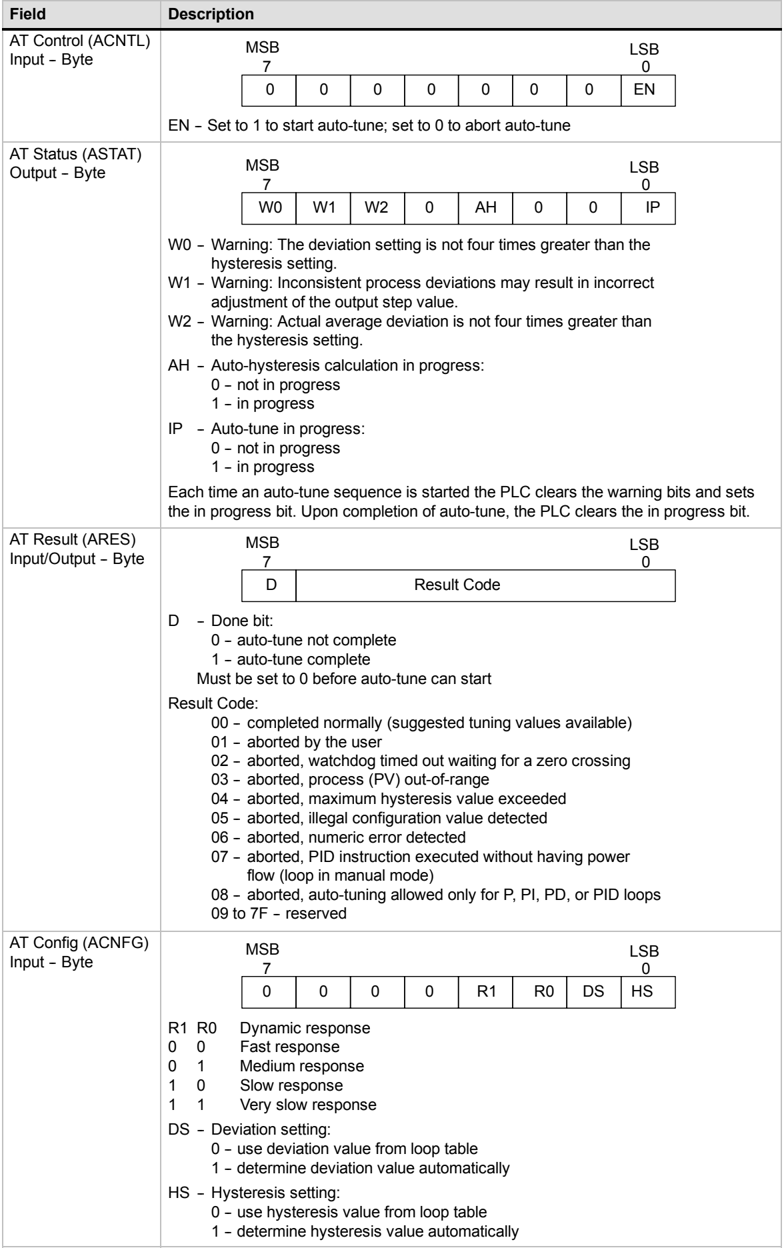
| AT Control (ACNTL) Input - Byte | MSB LSB7 00 0 0 0 0 0 0 ENEN - Set to 1 to start auto-tune; set to 0 to abort auto-tune |
| AT Status (ASTAT) Output - Byte | MSB LSB7 0W0 W1 W2 0 AH 0 0 IPW0 - Warning: The deviation setting is not four times greater than the hysteresis setting.W1 - Warning: Inconsistent process deviations may result in incorrect adjustment of the output step value.W2 - Warning: Actual average deviation is not four times greater than the hysteresis setting.AH - Auto-hysteresis calculation in progress:0 - not in progress1 - in progressIP - Auto-tune in progress:0 - not in progress1 - in progressEach time an auto-tune sequence is started the PLC clears the warning bits and sets the in progress bit. Upon completion of auto-tune, the PLC clears the in progress bit. |
| AT Result (ARES) Input/Output - Byte | MSB LSB7 0D Result CodeD - Done bit:0 - auto-tune not complete1 - auto-tune completeMust be set to 0 before auto-tune can startResult Code:00 - completed normally (suggested tuning values available)01 - aborted by the user02 - aborted, watchdog timed out waiting for a zero crossing03 - aborted, process (PV) out-of-range04 - aborted, maximum hysteresis value exceeded05 - aborted, illegal configuration value detected06 - aborted, numeric error detected07 - aborted, PID instruction executed without having power flow (loop in manual mode)08 - aborted, auto-tuning allowed only for P, PI, PD, or PID loops09 to 7F - reserved |
| AT Config (ACNFG) Input - Byte | MSB LSB7 00 0 0 0 R1 R0 DS HSR1 R0 Dynamic response0 0 Fast response0 1 Medium response1 0 Slow response1 1 Very slow responseDS - Deviation setting:0 - use deviation value from loop table1 - determine deviation value automaticallyHS - Hysteresis setting:0 - use hysteresis value from loop table1 - determine hysteresis value automatically |
384