Using Master and Slave Devices on a PROFIBUS Network
The S7-200 supports a master-slave network and can function as either a master or a slave in a PROFIBUS network, while STEP 7-Micro/WIN is always a master.
Masters
A device that is a master on a network can initiate a request to another device on the network. A master can also respond to requests from other masters on the network. Typical master devices include STEP 7-Micro/WIN, human-machine interface devices such as a TD 200, and S7-300 or S7-400 PLCs. The S7-200 functions as a master when it is requesting information from another S7-200 (peer-to-peer communications).
Slaves
A device that is configured as a slave can only respond to requests from a master device; a slave never initiates a request. For most networks, the S7-200 functions as a slave. As a slave device, the S7-200 responds to requests from a network master device, such as an operator panel or STEP 7-Micro/WIN.
Setting the Baud Rate and Network Address
The speed that data is transmitted across the network is the baud rate, which is typically measured in units of kilobaud (kbaud) or megabaud (Mbaud). The baud rate measures how much data can be transmitted within a given amount of time. For example, a baud rate of 19.2 kbaud describes a transmission rate of 19,200 bits per second.
Every device that communicates over a given network must be configured to transmit data at the same baud rate. Therefore, the fastest baud rate for the network is determined by the slowest device connected to the network.
Table 7-1 lists the baud rates supported by the S7-200.
Table 7-1 Baud Rates Supported by the S7-200
| Network | Baud Rate |
|---|---|
| Standard Network | 9.6 kbaud to 187.5 kbaud |
| Using an EM 277 | 9.6 kbaud to 12 Mbaud |
| Freeport Mode | 1200 baud to 115.2 kbaud |
The network address is a unique number that you assign to each device on the network. The unique network address ensures that the data is transferred to or retrieved from the correct device. The S7-200 supports network addresses from 0 to 126. For an S7-200 with two ports, each port has a network address. Table 7-2 lists the default (factory) settings for the S7-200 devices.
Table 7-2 Default Addresses for S7-200 Devices
| S7-200 Device | Default Address |
|---|---|
| STEP 7-Micro/WIN | 0 |
| HMI (TD 200, TP, or OP) | 1 |
| S7-200 CPU | 2 |
Setting the Baud Rate and Network Address for STEP 7-Micro/WIN
You must configure the baud rate and network address for STEP 7-Micro/WIN. The baud rate must be the same as the other devices on the network, and the network address must be unique.
Typically, you do not change the network address (0) for STEP 7-Micro/WIN. If your network includes another programming package, you might need to change the network address for STEP 7-Micro/WIN.
As shown in Figure 7-3, configuring the baud rate and network address for STEP 7-Micro/WIN is simple. After you click the Communications icon in the Navigation bar, you perform the following steps:
- Double-click the icon in the Communications Setup window.
- Click the Properties button on the Set PG/PC Interface dialog box.
- Select the network address for STEP 7-Micro/WIN.
- Select the baud rate for STEP 7-Micro/WIN.
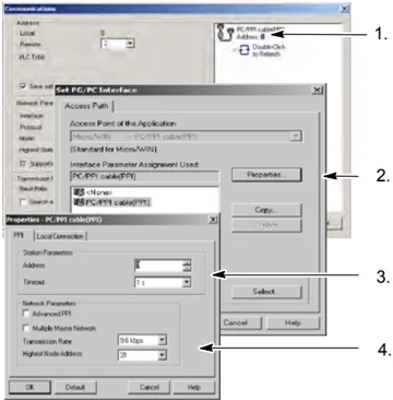
Figure 7-3 Configuring STEP 7-Micro/WIN
Setting the Baud Rate and Network Address for the S7-200
You must also configure the baud rate and network address for the S7-200. The system block of the S7-200 stores the baud rate and network address. After you select the parameters for the S7-200, you must download the system block to the S7-200.
The default baud rate for each S7-200 port is 9.6 kbaud, and the default network address is 2.
As shown in Figure 7-4, use STEP 7-Micro/WIN to set the baud rate and network address for the S7-200. After you select the System Block icon in the Navigation bar or select the View > Component > System Block menu command, you perform the following steps:
- Select the network address for the S7-200.
- Select the baud rate for the S7-200.
- Download the system block to the S7-200.
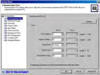
Figure 7-4 Configuring the S7-200 CPU
Tip
Selection of all baud rate options is permitted. STEP 7-Micro/WIN validates this selection during the download of the System Block. Baud rate selections that would prevent STEP 7-Micro/WIN from communicating with the S7-200 are prevented from being downloaded.
Communicating over a Network Chapter 7
Setting the Remote Address
Before you can download the updated settings to the S7-200, you must set both the communications (COM) port of STEP 7-Micro/WIN (local) and the address of the S7-200 (remote) to match the current setting of the remote S7-200. See Figure 7-5.
After you download the updated settings, you may need to reconfigure the PG/PC Interface baud rate setting (if different from the setting used when downloading to the remote S7-200). Refer to Figure 7-3 to configure the baud rate.
 Figure 7-5 Configuring STEP 7-Micro/WIN
Searching for the S7-200 CPUs on a Network
You can search for and identify the S7-200 CPUs that are attached to your network. You can also search the network at a specific baud rate or at all baud rates when looking for S7-200s.
Only PPI Multi-Master cables permit searching of all baud rates. This feature is not available if communicating through a CP card. The search starts at the baud rate that is currently selected.
- Open the Communications dialog box and double-click the Refresh icon to start the search.
- To search all baud rates, select the Search All Baud Rates check box.
 Figure 7-6 Searching for CPUs on a Network
213
S7-200 Programmable Controller System Manual
Selecting the Communications Protocol for Your Network
The following information is an overview of the protocols supported by the S7-200 CPUs.
Point-to-Point Interface (PPI)
Multi-Point Interface (MPI)
PROFIBUS
Based on the Open System Interconnection (OSI) seven-layer model of communications architecture, these protocols are implemented on a token ring network which conforms to the PROFIBUS standard as defined in the European Standard EN 50170. These protocols are asynchronous, character-based protocols with one start bit, eight data bits, even parity, and one stop bit. Communications frames depend upon special start and stop characters, source and destination station addresses, frame length, and a checksum for data integrity. The protocols can run on a network simultaneously without interfering with each other, as long as the baud rate is the same for each protocol.
Ethernet is also available for the S7-200 CPU with expansion modules CP243-1 and CP243-1 IT.
PPI Protocol
PPI is a master-slave protocol: the master devices send requests to the slave devices, and the slave devices respond. See Figure 7-7. Slave devices do not initiate messages, but wait until a master sends them a request or polls them for a response.
Masters communicate to slaves by means of a shared connection which is managed by the PPI protocol. PPI does not limit the number of masters that can communicate with any one slave; however, you cannot install more than 32 masters on the network.
 Figure 7-7 PPI Network
S7-200 CPUs can act as master devices while they are in RUN mode, if you enable PPI master mode in the user program. (See the description of SMB30 in Appendix D.) After enabling PPI master mode, you can use the Network Read or the Network Write instructions to read from or write to other S7-200s. While the S7-200 is acting as a PPI master, it still responds as a slave to requests from other masters.
PPI Advanced allows network devices to establish a logical connection between the devices. With PPI Advanced, there are a limited number of connections supplied by each device. See Table 7-3 for the number of connections supported by the S7-200.
All S7-200 CPUs support both PPI and PPI Advanced protocols, while PPI Advanced is the only PPI protocol supported by the EM 277 module.
Table 7-3 Number of Connections for the S7-200 CPU and EM 277 Modules
MPI Protocol
MPI allows both master-master and master-slave communications. See Figure 7-8. To communicate with an S7-200 CPU, STEP 7-Micro/WIN establishes a master-slave connection. MPI protocol does not communicate with an S7-200 CPU operating as a master.
Network devices communicate by means of separate connections (managed by the MPI protocol) between any two devices. Communication between devices is limited to the number of connections supported by the S7-200 CPU or EM 277 modules. See Table 7-3 for the number of connections supported by the S7-200.
For MPI protocol, the S7-300 and S7-400 PLCs use the XGET and XPUT instructions to read and write data to the S7-200 CPU. For information about these instructions, refer to your S7-300 or S7-400 programming manual.
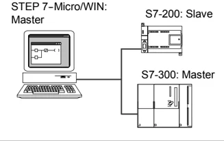
Figure 7-8 MPI Network
PROFIBUS Protocol
The PROFIBUS protocol is designed for high-speed communications with distributed I/O devices (remote I/O). There are many PROFIBUS devices available from a variety of manufacturers. These devices range from simple input or output modules to motor controllers and PLCs.
PROFIBUS networks typically have one master and several slave I/O devices. See Figure 7-9. The master device is configured to know what types of I/O slaves are connected and at what addresses. The master initializes the network and verifies that the slave devices on the network match the configuration. The master continuously writes output data to the slaves and reads input data from them.
When a DP master configures a slave device successfully, it then owns that slave device. If there is a second master device on the network, it has very limited access to the slaves owned by the first master.
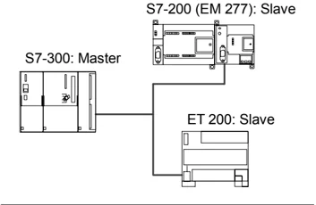
Figure 7-9 PROFIBUS Network
TCP/IP Protocol
The S7-200 can support TCP/IP Ethernet communication through the use of an Ethernet (CP 243-1) or Internet (CP 243-1 IT) expansion module. Table 7-4 shows the baud rate and number of connections supported by these modules.
Table 7-4 Number of Connections for the Ethernet (CP 243-1) and the Internet (CP 243-1 IT) Modules
| Module | Baud Rate | Connections |
|---|---|---|
| Ethernet (CP 243-1) Module | 10 to 100 Mbaud | 8 general purpose connections |
| Internet (CP 243-1 IT) Module | 1 STEP 7-Micro/WIN connection |
Refer to the SIMATIC NET CP 243-1 Communications Processor for Industrial Ethernet Manual or the SIMATIC NET CP 243-1 IT Communications Processor for Industrial Ethernet and Information Technology Manual for additional information.
Sample Network Configurations Using Only S7-200 Devices
Single-Master PPI Networks
For a simple single-master network, the programming station and the S7-200 CPU are connected by either a PPI Multi-Master cable or by a communications processor (CP) card installed in the programming station.
In the sample network at the top of Figure 7-10, the programming station (STEP 7-Micro/WIN) is the network master. In the sample network at the bottom of Figure 7-10, a human-machine interface (HMI) device (such as a TD 200, TP, or OP) is the network master.
In both sample networks, the S7-200 CPU is a slave that responds to requests from the master.
For a single-master PPI network, configure STEP 7-Micro/WIN to use PPI protocol. Uncheck the Multiple Master Network and the PPI Advanced check boxes, if available.
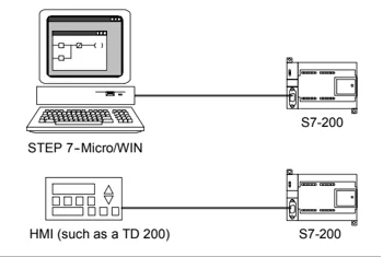
Figure 7-10 Single-Master PPI Network
Multi-Master PPI Networks
Figure 7-11 shows a sample network of multiple masters with one slave. The programming station (STEP 7-Micro/WIN) uses either a CP card or a PPI Multi-Master cable. STEP 7-Micro/WIN and the HMI device share the network.
Both STEP 7-Micro/WIN and the HMI device are masters and must have separate network addresses. When the PPI Multi-Master cable is being used, the cable is a master and uses the network address supplied by STEP 7-Micro/WIN. The S7-200 CPU is a slave.
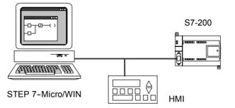
Figure 7-11 Multiple Masters with One Slave
Figure 7-12 shows a PPI network with multiple masters communicating with multiple slaves. In this example, both STEP 7-Micro/WIN and the HMI can request data from any S7-200 CPU slave. STEP 7-Micro/WIN and the HMI device share the network.
All devices (masters and slaves) have different network addresses. When the PPI Multi-Master cable is being used, the cable is a master and uses the network address supplied by STEP 7-Micro/WIN. The S7-200 CPUs are slaves.
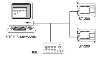
Figure 7-12 Multiple Masters and Slaves
For a network with multiple masters and one or more slaves, configure STEP 7-Micro/WIN to use PPI protocol and check the Multiple Master Network and the PPI Advanced check boxes if they are available. If you are using a PPI Multi-Master cable, the Multiple Master Network and PPI Advanced check boxes are ignored.
Complex PPI Networks
Figure 7-13 shows a sample network that uses multiple masters with peer-to-peer communications.
STEP 7-Micro/WIN and the HMI device read and write over the network to the S7-200 CPUs, and the S7-200 CPUs use the Network Read and Network Write instructions to read and write to each other (peer-to-peer communications).
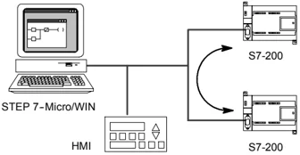
Figure 7-13 Peer-to-Peer Communications
Figure 7-14 shows another, example of a complex PPI network that uses multiple masters with peer-to-peer communications. In this example, each HMI monitors one S7-200 CPU.
The S7-200 CPUs use the NETR and NETW instructions to read and write to each other (peer-to-peer communications).
For complex PPI networks configure STEP 7-Micro/WIN to use PPI protocol and check the Multiple Master Network and the PPI Advanced check boxes if available. If you are using a PPI Multi-Master cable, the Multiple Master Network and PPI Advanced check boxes are ignored.
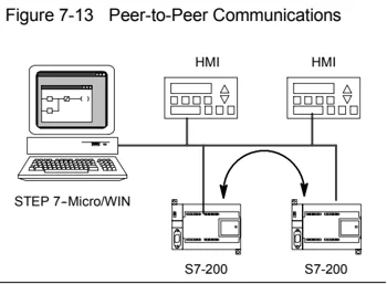
Figure 7-14 HMI Devices and Peer-to-Peer
Sample Network Configurations Using S7-200, S7-300, and S7-400 Devices
Networks with Baud Rates Up to 187.5 kbaud
In the sample network shown in Figure 7-15, the S7-300 uses the XPUT and XGET instructions to communicate with an S7-200 CPU. The S7-300 cannot communicate with an S7-200 CPU in master mode.
To communicate with the S7 CPUs, configure STEP 7-Micro/WIN to use PPI protocol and check the Multiple Master Network and the PPI Advanced check boxes if available. If you are using a PPI Multi-Master cable, the Multiple Master Network and PPI Advanced check boxes are ignored.
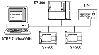
Figure 7-15 Baud Rates Up to 187.5 Kbaud
Networks with Baud Rates Above 187.5 kbaud
For baud rates above 187.5 kbaud, the S7-200 CPU must use an EM 277 module for connecting to the network. See Figure 7-16. STEP 7-Micro/WIN must be connected by a communications processor (CP) card.
In this configuration, the S7-300 can communicate with the S7-200s, using the XPUT and XGET instructions, and the HMI can monitor either the S7-200s or the S7-300.
The EM 277 is always a slave device.
STEP 7-Micro/WIN can program or monitor either S7-200 CPU through the attached EM 277. To communicate with an EM 277 above 187.5 kbaud, configure STEP 7-Micro/WIN to use MPI protocol with a CP card. The maximum baud rate for the PPI Multi-Master cables is 187.5 kbaud.
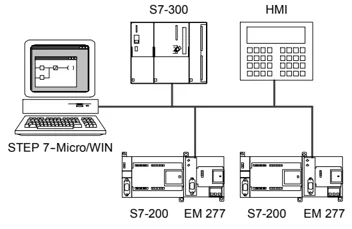
Figure 7-16 Baud Rates Above 187.5 Kbaud
Sample PROFIBUS-DP Network Configurations
Networks with S7-315-2 DP as PROFIBUS Master and EM 277 as PROFIBUS Slave
Figure 7-17 shows a sample PROFIBUS network that uses an S7-315-2 DP as the PROFIBUS master. An EM 277 module is a PROFIBUS slave.
The S7-315-2 DP can read data from or write data to the EM 277, from 1 byte up to 128 bytes. The S7-315-2 DP reads or writes V memory locations in the S7-200.
This network supports baud rates from 9600 baud to 12 Mbaud.
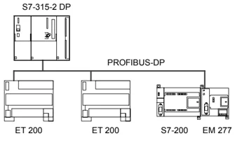
Figure 7-17 Network with S7-315-2 DP
Networks with STEP 7-Micro/WIN and HMI
Figure 7-18 shows a sample network with an S7-315-2 DP as the PROFIBUS master and EM 277 as a PROFIBUS slave. In this configuration, the HMI monitors the S7-200 through the EM 277. STEP 7-Micro/WIN programs the S7-200 through the EM 277.
This network supports baud rates from 9600 baud to 12 Mbaud. STEP 7-Micro/WIN requires a CP card for baud rates above 187.5 kbaud.
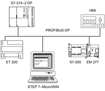
Figure 7-18 PROFIBUS Network
Configure STEP 7-Micro/WIN to use PROFIBUS protocol for a CP card. Select the DP or Standard profile if there are only DP devices present on the network. Select the Universal (DP/FMS) profile for all master devices if there are any non-DP devices on the network, such as TD 200s. All masters on the network must be set up to use the same PROFIBUS profile (DP, Standard or Universal) for the network to operate.
The PPI Multi-master cables will function on networks up to 187.5 kbaud only if all master devices are using the Universal (DP/FMS) profile.
Sample Network Configurations Using Ethernet and/or Internet Devices
In the configuration shown in Figure 7-19, an Ethernet connection is used to allow STEP 7-Micro/WIN to communicate with either of the S7-200 CPUs which are using an Ethernet (CP 243-1) module or an Internet (CP 243-1 IT) module. The S7-200 CPUs can exchange data through the Ethernet connection. A standard browser program running on the PC with STEP 7-Micro/WIN can be used to access the home page of the Internet (CP 243-1 IT) module.
For Ethernet networks, you configure STEP 7-Micro/WIN to use TCP/IP protocol.
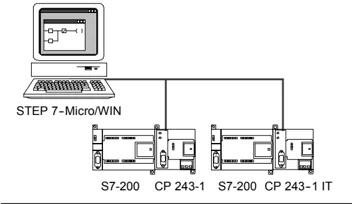
Figure 7-19 10/100 Mbaud Ethernet Network
Tip In the Set PG/PC Interface dialog, there are at least two TCP/IP choices. The selection TCP/IP -> NdisWanlp is not supported by the S7-200.
☐ In the Set PG/PC Interface dialog box, the option(s) depend upon the type of Ethernet interface provided in your PC. Choose the one that connects your computer to the Ethernet network where the CP 243-1 or CP 243-1 IT module is connected.
☐ On the Communications dialog, you must enter the Remote IP address(es) of each of the Ethernet/Internet modules with which you wish to communicate.
Installing and Removing Communications Interfaces
From the Set PG/PC Interface dialog box, you use the Installing/Uninstalling Interfaces dialog box to install or remove communications interfaces for your computer
- In the Set PG/PC Interface dialog box, click Select to access the Installing/Uninstalling Interfaces dialog box.
The Selection box lists the interfaces that are available, and the Installed box displays the interfaces that have already been installed on your computer.
-
To add a communications interface: Select the communications hardware installed on your computer and click Install. When you close the Installing/Uninstalling Interfaces dialog box, the Set PG/PC Interface dialog box displays the interface in the Interface Parameter Assignment Used box.
-
To remove a communications interface: Select the interface to be removed and click Uninstall. When you close the Installing/Uninstalling Interfaces dialog box, the Set PG/PC Interface dialog box removes the interface from the Interface Parameter Assignment Used box.
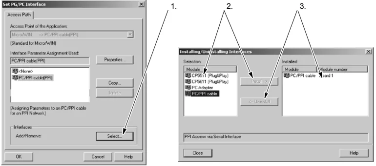
Figure 7-20 Set PG/PC Interface and Installing/Uninstalling Interfaces Dialog Boxes
Adjusting the Port Settings of Your Computer for PPI Multi-Master
If you are using the USB/PPI Multi-Master cable or the RS-232/PPI Multi-Master cable in PPI mode, adjustment of your computer's port settings is not necessary and operation in multi-master networks is possible with the Windows NT operating system.
If you are using the RS-232/PPI Multi-Master cable in PPI/Freeport mode for communication between an S7-200 CPU and STEP 7-Micro/WIN on an operating system that supports the PPI Multi-Master configuration (Windows NT does not support the PPI Multi-Master), you might need to adjust the port settings on your computer:
- Right-click the My Computer icon on the desktop and select the Properties menu command.
- Select the Device Manager tab. For Windows 2000, select first the Hardware tab and then Device Manager button.
- Double-click the Ports (COM & LPT).
- Select the communications port that you are currently using (for example, COM1).
- On the Port Settings tab, click the Advanced button.
- Set the Receive Buffer and the Transmit Buffer controls to the lowest value (1).
- Click OK to apply the change, close all the windows, and reboot the computer to make the new settings active.
Building Your Network
General Guidelines
Always install appropriate surge suppression devices for any wiring that could be subject to lightning surges.
Avoid placing low-voltage signal wires and communications cables in the same wire tray with AC wires and high-energy, rapidly switched DC wires. Always route wires in pairs, with the neutral or common wire paired with the hot or signal-carrying wire.
The communications port of the S7-200 CPU is not isolated. Consider using an RS-485 repeater or an EM 277 module to provide isolation for your network.
Caution Interconnecting equipment with different reference potentials can cause unwanted currents to flow through the interconnecting cable.
These unwanted currents can cause communications errors or can damage equipment.
Be sure all equipment that you are about to connect with a communications cable either shares a common circuit reference or is isolated to prevent unwanted current flows. See the information about grounding and circuit reference points for using isolated circuits in Chapter 3.
Determining the Distances, Transmission Rate, and Cable for Your Network
As shown in Table 7-5, the maximum length of a network segment is determined by two factors: isolation (using an RS-485 repeater) and baud rate.
Isolation is required when you connect devices at different ground potentials. Different ground potentials can exist when grounds are physically separated by a long distance. Even over short distances, load currents of heavy machinery can cause a difference in ground potential.
Table 7-5 Maximum Length for a Network Cable
\begin{tabular}{|l|r|r|} \hline Baud Rate & Non-Isolated CPU Port$^{1}$ & CPU Port with Repeater or EM 277 \ \hline 9.6 kbaud to 187.5 kbaud & 50 m & 1,000 m \ \hline 500 kbaud & Not supported & 400 m \ \hline 1 Mbaud to 1.5 Mbaud & Not supported & 200 m \ \hline 3 Mbaud to 12 Mbaud & Not supported & 100 m \ \hline \end{tabular}
$^{1}$ The maximum distance allowed without using an isolator or repeater is 50 m. You measure this distance from the first node to the last node in the segment.
Using Repeaters on the Network
An RS-485 repeater provides bias and termination for the network segment. You can use a repeater for the following purposes:
-
To increase the length of a network: Adding a repeater to your network allows you to extend the network another 50 m. If you connect two repeaters with no other nodes in between (as shown in Figure 7-21), you can extend the network to the maximum cable length for the baud rate. You can use up to 9 repeaters in series on a network, but the total length of the network must not exceed 9600 m.
-
To add devices to a network: Each segment can have a maximum of 32 devices connected up to 50 m at 9600 baud. Using a repeater allows you to add another segment (32 devices) to the network.
-
To electrically isolate different network segments: Isolating the network improves the quality of the transmission by separating the network segments which might be at different ground potentials.
A repeater on your network counts as one of the nodes on a segment, even though it is not assigned a network address.
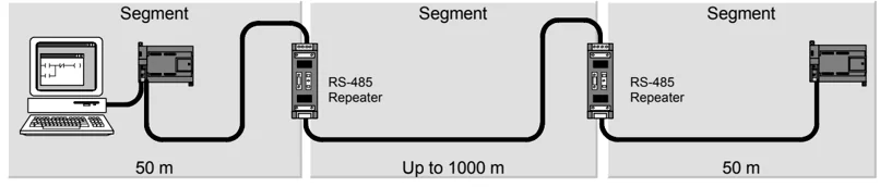
Figure 7-21 Sample Network with Repeaters
Selecting the Network Cable
S7-200 networks use the RS-485 standard on twisted pair cables. Table 7-6 lists the specifications for the network cable. You can connect up to 32 devices on a network segment.
Table 7-6 General Specifications for Network Cable
| Specifications | Description |
|---|---|
| Cable type | Shielded, twisted pair |
| Loop resistance | ≤115 Ω/km |
| Effective capacitance | 30 pF/m |
| Nominal impedance | Approximately 135 Ω to 160 Ω (frequency = 3 MHz to 20 MHz) |
| Attenuation | 0.9 dB/100 m (frequency=200 kHz) |
| Cross-sectional core area | 0.3 mm² to 0.5 mm² |
| Cable diameter | 8 mm ±0.5 mm |
Connector Pin Assignments
The communications ports on the S7-200 CPU are RS-485 compatible on a nine-pin subminiature D connector in accordance with the PROFIBUS standard as defined in the European Standard EN 50170. Table 7-7 shows the connector that provides the physical connection for the communications port and describes the communications port pin assignments.
Table 7-7 Pin Assignments for the S7-200 Communications Port
Biasing and Terminating the Network Cable
Siemens provides two types of network connectors that you can use to easily connect multiple devices to a network: a standard network connector (see Table 7-7 for the pin assignments), and a connector that includes a programming port, which allows you to connect a programming station or an HMI device to the network without disturbing any existing network connections. The programming port connector passes all signals (including the power pins) from the S7-200 through to the programming port, which is especially useful for connecting devices that draw power from the S7-200 (such as a TD 200).
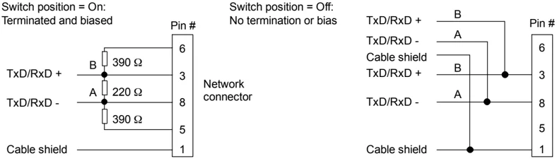
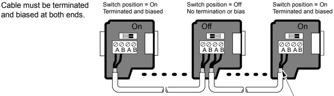
Both connectors have two sets of terminal screws to allow you to attach the incoming and outgoing network cables. Both connectors also have switches to bias and terminate the network selectively. Figure 7-22 shows typical biasing and termination for the cable connectors.
Cable must be terminated and biased at both ends.
Switch position = On Terminated and biased
Bare shielding: approximately 12 mm (1/2 in.) must contact the metal guides of all locations.
Switch position = On: Terminated and biased
Pin #
6
TxID/RxD +
B
390 \Omega
3
Network connector
TxID/RxD -
A
220 \Omega
8
390 \Omega
5
Cable shield
1
Switch position = Off: No termination or bias
TxID/RxD +
B
Pin #
6
TxID/RxD -
A
Cable shield
B
TxID/RxD +
3
TxID/RxD -
A
8
5
Cable shield
1
Figure 7-22 Bias and Termination of the Network Cable
Choosing a PPI Multi-Master Cable or a CP Card for Your Network
As shown in Table 7-8, STEP 7-Micro/WIN supports the RS-232/PPI Multi-Master cable and the USB/PPI Multi-Master cable as well as several CP cards that allow the programming station (your computer or SIMATIC programming device) to act as a network master.
For baud rates up to 187.5 kbaud the PPI Multi-Master cables provide the simplest and most cost-effective connection between STEP 7-Micro/WIN and one S7-200 CPU or an S7-200 network. Two types of PPI Multi-Master cables are available and both can be used for local connection between STEP 7-Micro/WIN and an S7-200 network.
The USB/PPI Multi-Master cable is a plug and play device that can be used with PCs that support the USB Version 1.1. It provides isolation between your PC and the S7-200 network while supporting PPI communication at baud rates up to 187.5 kbaud. There are no switches to set; just connect the cable, choose the PC/PPI cable as the interface, select PPI protocol, and set the port to USB in the PC Connection tab. Only one USB/PPI Multi-Master cable can be connected to the PC at a time for use by STEP 7-Micro/WIN.
The RS-232/PPI Multi-Master cable has eight DIP switches: two of these switches are used to configure the cable for operation with STEP 7-Micro/WIN.
- If you are connecting the cable to the PC, select PPI mode (switch 5 = 1) and Local operation (switch 6 = 0).
- If you are connecting the cable to a modem, select PPI mode (switch 5 = 1) and Remote operation (switch 6 = 1).
The cable provides isolation between your PC and the S7-200 network. Choose the PC/PPI cable as the interface and select the RS-232 port that you want to use under the PC Connection tab. Under the PPI tab, select the station address and the network baud rate. You do not need to make any other selections because protocol selection is automatic with the RS-232/PPI Multi-Master cable.
Both the USB/PPI and the RS-232/PPI Multi-Master cables have LEDs that provide an indication of the communication activity with the PC as well as network communication activity.
- The Tx LED indicates that the cable is transmitting information to the PC.
- The Rx LED indicates that the cable is receiving information from the PC.
- The PPI LED indicates that the cable is transmitting data on the network. Since the Multi-Master cables are token holders, the PPI LED is on continuously once communication has been initialized by STEP 7-Micro/WIN. The PPI LED is turned off when the connection with STEP 7-Micro/WIN is closed. The PPI LED will also flash at 1 Hz rate while waiting to join the network.
The CP cards contain dedicated hardware to assist the programming station in managing a multi-master network and can support different protocols at several baud rates.
Each CP card provides a single RS-485 port for connection to the network. The CP 5511 PCMCIA card has an adapter that provides the 9-pin D port. You connect one end of the cable to the RS-485 port of the card and connect the other end to a programming port connector on your network.
If you are using a CP card with PPI communications, STEP 7-Micro/WIN will not support two different applications running on the same CP card at the same time. You must close the other application before connecting STEP 7-Micro/WIN to the network through the CP card. If you are using MPI or PROFIBUS communication, multiple STEP 7-Micro/WIN applications are permitted to communicate over the network at the same time.
Caution
Using a non-isolated RS-485-to-RS-232 converter can damage the RS-232 port of your computer.
The Siemens RS-232/PPI and USB/PPI Multi-Master cables (order number 6ES7 901-3CB30-0XA0 or 6ES7 901-3DB30-0XA0, respectively) provide electrical isolation between the RS-485 port on the S7-200 CPU and the RS-232 or USB port that connects to your computer. If you do not use the Siemens Multi-Master cable, you must provide isolation for the RS-232 port of your computer.
Communicating over a Network Chapter 7
Table 7-8 CP Cards and Protocols Supported by STEP 7-Micro/WIN
| Configuration | Baud Rate | Protocol |
|---|---|---|
| RS-232/PPI Multi-Master or USB/PPI Multi-Master cable¹Connected to a port on the programming station | 9.6 kbaud to 187.5 kbaud | PPI |
| PC Adapter USB, V1.1 or later | 9.6 kbaud to 187.5 baud | PPI, MPI, and PROFIBUS |
| CP 5512Type II, PCMCIA card (for a notebook computer) | 9.6 kbaud to 12 Mbaud | PPI, MPI, and PROFIBUS |
| CP 5611 (version 3 or greater)PCI card | 9.6 kbaud to 12 Mbaud | PPI, MPI, and PROFIBUS |
| CP 1613, S7-1613PCI card | 10 Mbaud or 100 Mbaud | TCP/IP |
| CP 1612, SoftNet-S7PCI card | 10 Mbaud or 100 Mbaud | TCP/IP |
| CP 1512, SoftNet-S7PCMCIA card (for a notebook computer) | 10 Mbaud or 100 Mbaud | TCP/IP |
¹ The Multi-Master cables provide electrical isolation between the RS-485 port (on the S7-200 CPU) and the port that connects to your computer. Using a non-isolated RS-485-to-RS-232 converter could damage the RS-232 port of your computer.
Using HMI Devices on Your Network
The S7-200 CPU supports many types of HMI devices from Siemens and also from other manufacturers. While some of these HMI devices (such as the TD 200) do not allow you to select the communications protocol used by the device, other devices (such as the OP and TP product lines) allow you to select the communications protocol for that device.
If your HMI device allows you to select the communications protocol, consider the following guidelines:
-
For an HMI device connected to the communications port of the S7-200 CPU, with no other devices on the network, select either the PPI or the MPI protocol for the HMI device.
-
For an HMI device connected to an EM 277 PROFIBUS module, select either the MPI or the PROFIBUS protocol.
-
If the network with the HMI device includes S7-300 or S7-400 PLCs, select the MPI protocol for the HMI device.
-
If the network with the HMI device is a PROFIBUS network, select the PROFIBUS protocol for the HMI device and select a profile consistent with the other masters on the PROFIBUS network.
-
-
For an HMI device connected to the communications port of the S7-200 CPU which has been configured as a master, select the PPI protocol for the HMI device. Advanced PPI is optimal. The MPI and PROFIBUS protocols do not support the S7-200 CPU as a master.
For more information about how to configure the HMI device, refer to the specific manual for your device (see Table 7-9). These manuals are included in the STEP 7-Micro/WIN documentation CD.
Table 7-9 HMI Devices Supported by the S7-200 CPU
| HMI | Configuration Software | Configuration Cable | Communications Cable |
|---|---|---|---|
| TD 100C | Text Display WizardKeypad Designer(part of STEP 7-Micro/WIN) | no | 6ES7 901-3EB10-0XA0 |
| TD 200 | Part of TD 200 | ||
| TD 200C | Part of TD 200C | ||
| TD400C | Part of TD400C | ||
| TP177micro | WinCC flexible microWinCC flexible CompactWinCC flexible StandardWinCC flexible Advanced | S7-200 RS-232 PC-PPI cable,(6ES7 901-3CB30-0XA0) | See SIMATIC HMI catalog ST80(http://www.siemens.com search on ST80) |
| OP73micro |
225
Creating User-Defined Protocols with Freeport Mode
Freeport mode allows your program to control the communications port of the S7-200 CPU. You can use Freeport mode to implement user-defined communications protocols to communicate with many types of intelligent devices. Freeport mode supports both ASCII and binary protocols.
To enable Freeport mode, you use special memory bytes SMB30 (for Port 0) and SMB130 (for Port 1). Your program uses the following to control the operation of the communications port:
-
Transmit instruction (XMT) and the transmit interrupt: The Transmit instruction allows the S7-200 to transmit up to 255 characters from the COM port. The transmit interrupt notifies your program in the S7-200 when the transmission has been completed.
-
Receive character interrupt: The receive character interrupt notifies the user program that a character has been received on the COM port. Your program can then act on that character, based on the protocol being implemented.
-
Receive instruction (RCV): The Receive instruction receives the entire message from the COM port and then generates an interrupt for your program when the message has been completely received. You use the SM memory of the S7-200 to configure the Receive instruction for starting and stopping the receiving of messages, based on defined conditions. The Receive instruction allows your program to start or stop a message based on specific characters or time intervals. Most protocols can be implemented with the Receive instruction.
Freeport mode is active only when the S7-200 is in RUN mode. Setting the S7-200 to STOP mode halts all Freeport communications, and the communications port then reverts to the PPI protocol with the settings which were configured in the system block of the S7-200.
Table 7-10 Using Freeport Mode
| Network Configuration | Description |
|---|---|
| Using Freeport over an RS-232 connection | Example: Using an S7-200 with an electronic scale that has an RS-232 port. - RS-232/PPI Multi-Master cable connects the RS-232 port on the scale to the RS-485 port on the S7-200 CPU. (Set the cable to PPI/Freeport mode, switch 5=0.) - S7-200 CPU uses Freeport to communicate with the scale. - Baud rate can be from 1200 baud to 115.2 kbaud. - User program defines the protocol. |
| Using USS protocol | Example: Using an S7-200 with SIMODRIVE MicroMaster drives. - STEP 7-Micro/WIN provides a USS library. - S7-200 CPU is a master, and the drives are slaves. - Refer to the Programming Tips on the documentation CD for a sample USS program. See Tip 28. |
| Creating a user program that emulates a slave device on another network | Example: Connecting S7-200 CPUs to a Modbus network. - User program in the S7-200 emulates a Modbus slave. - STEP 7-Micro/WIN provides a Modbus library. - Refer to the Programming Tips on the documentation CD for a sample Modbus program. See Tip 41. |
Using the RS-232/PPI Multi-Master Cable and Freeport Mode with RS-232 Devices
You can use the RS-232/PPI Multi-Master cable and the Freeport communications functions to connect the S7-200 CPUs to many devices that are compatible with the RS-232 standard. The cable must be set to PPI/Freeport mode (switch 5 = 0) for Freeport operation. Switch 6 selects either Local mode (DCE) (switch 6 = 0), or Remote mode (DTE) (switch 6 = 1).
The RS-232/PPI Multi-Master cable is in Transmit mode when data is transmitted from the RS-232 port to the RS-485 port. The cable is in Receive mode when it is idle or is transmitting data from the RS-485 port to the RS-232 port. The cable changes from Receive to Transmit mode immediately when it detects characters on the RS-232 transmit line.
The RS-232/PPI Multi-Master cable supports baud rates between 1200 baud and 115.2 kbaud. Use the DIP switches on the housing of the RS-232/PPI Multi-Master cable to configure the cable for the correct baud rate. Table 7-11 shows the baud rates and switch positions.
The cable switches back to Receive mode when the RS-232 transmit line is in the idle state for a period of time defined as the turnaround time of the cable. The baud rate selection of the cable determines the turnaround time, as shown in Table 7-11.
If you are using the RS-232/PPI Multi-Master cable in a system where Freeport communications is used, the program in the S7-200 must comprehend the turnaround time for the following situations:
-
The S7-200 responds to messages transmitted by the RS-232 device. After the S7-200 receives a request message from the RS-232 device, the S7-200 must delay the transmission of a response message for a period of time greater than or equal to the turnaround time of the cable.
-
The RS-232 device responds to messages transmitted from the S7-200. After the S7-200 receives a response message from the RS-232 device, the S7-200 must delay the transmission of the next request message for a period of time greater than or equal to the turnaround time of the cable.
In both situations, the delay allows the RS-232/PPI Multi-Master cable sufficient time to switch from Transmit mode to Receive mode so that data can be transmitted from the RS-485 port to the RS-232 port.
Table 7-11 Turnaround Time and Settings
| Baud Rate | Turnaround Time | Settings (1 = Up) |
|---|---|---|
| 115200 | 0.15 ms | 110 |
| 57600 | 0.3 ms | 111 |
| 38400 | 0.5 ms | 000 |
| 19200 | 1.0 ms | 001 |
| 9600 | 2.0 ms | 010 |
| 4800 | 4.0 ms | 011 |
| 2400 | 7.0 ms | 100 |
| 1200 | 14.0 ms | 101 |
Using Modems and STEP 7-Micro/WIN with Your Network
STEP 7-Micro/WIN version 3.2 or later uses the standard Windows Phone and Modem Options for selecting and configuring telephone modems. The Phone and Modem Options are under the Windows Control Panel. Using the Windows setup options for modems allows you to:
Use most internal and external modems supported by Windows.
Use the standard configurations for most modems supported by Windows.
Use the standard Windows dialing rules for selection of locations, country and area code support, pulse or tone dialing, and calling card support.
Use higher baud rates when communicating to the EM 241 Modem module.
 Figure 7-23 Configuring the Local Modem
Use the Windows control panel to display the Modem Properties dialog box. This dialog box allows you to configure the local modem. You select your modem from the list of modems supported by Windows. If your modem type is not listed in the Windows modem dialog box, select a type that is the closest match for your modem, or contact your modem vendor to acquire the modem configuration files for Windows.
STEP 7-Micro/WIN also lets you use radio and cellular modems. These modem types do not appear in the Windows Modem Properties dialog box, but are available when configuring a connection for STEP 7-Micro/WIN.
Configuring a Modem Connection
A connection associates an identifying name with the physical properties of the connection. For a telephone modem these properties include the type of modem, 10 or 11 bit protocol selections, and timeouts. For cellular modems the connection allows setting of a PIN and other parameters. Radio modem properties include selections for baud rate, parity, flow control and other parameters.
228
Communicating over a Network Chapter 7
 Connection Wizard
Adding a Connection
Use the Connection wizard to add a new connection, remove, or edit a connection as shown in Figure 7-24.
- Double-click the icon in the Communications Setup window.
- Double-click the PC/PPI cable to open the PG/PC interface. Select the PPI cable and click the Properties button. On the Local Connection tab, check the Modem Connection box.
- Double-click the modem Connect icon in the Communications dialog.
- Click the Settings button to display the Modem Connections Settings dialog box.
- Click the Add button to start the Add Modem Connection wizard.
- Configure the connection as prompted by the wizard.
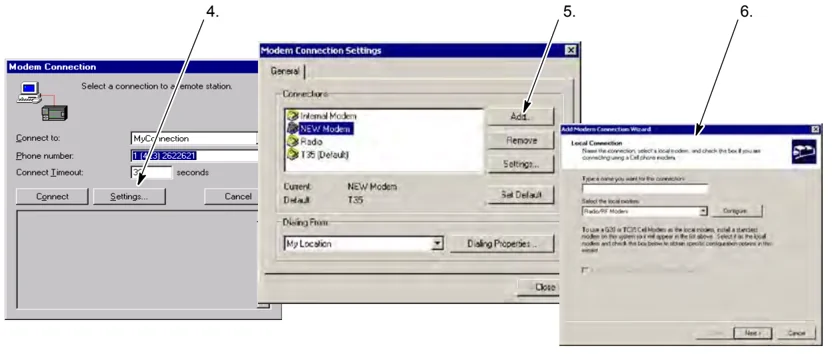
Figure 7-24 Adding a Modem Connection
Connecting to the S7-200 with a Modem
After you have added a modem connection, you can connect to an S7-200 CPU.
- Open the Communications dialog box and double-click on the Connect icon to display the Modem Connection dialog box.
- In the Modem Connection dialog box, click Connect to dial the modem.
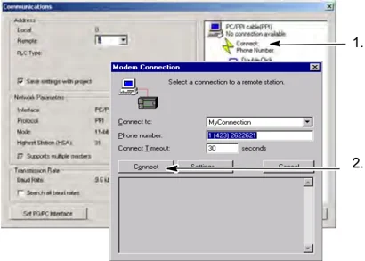
Figure 7-25 Connecting to the S7-200
229
Configuring a Remote Modem
The remote modem is the modem that is connected to the S7-200. If the remote modem is an EM 241 Modem module, no configuration is required. If you are connecting to a stand-alone modem or cell modem, you must configure the connection.
Modem Expansion Wizard
The Modem Expansion wizard configures the remote modem which is connected to the S7-200 CPU. Special modem configurations are required in order to properly communicate with the RS-485 half duplex port of the S7-200 CPU. Simply select the type of modem, and enter the information as prompted by the wizard. For more information, refer to the online help.
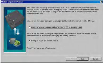
Figure 7-26 Modem Expansion Wizard
Configuring a PPI Multi-Master Cable to Work with a Remote Modem
The RS-232 PPI Multi-Master cable provides the ability to send modem AT command strings upon power-up of the cable. Please note that this configuration is only required if the default modem settings must be changed. See Figure 7-27.
Modem commands can be specified in the General commands. The auto answer command will be the only default setting.
Cell phone authorization commands and PIN numbers can be specified in the Cell Phone Authorization field, for example +CPIN=1234.
Each command string will be sent separately to the modem. Each string will be preceded with the AT modem attention command.
These commands will be initialized within the cable by selecting the Program/Test button.
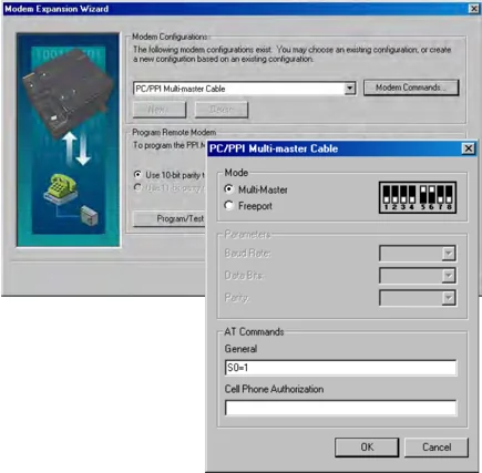
Figure 7-27 Modem Expansion Wizard - Sending Modem Commands
Please note that the bitmap will depict the recommended switch settings depending upon the selected parameters.
While configuring the RS-232/PPI Multi-Master cable with STEP 7-Micro/WIN, you must connect the RS-485 connector to an S7-200 CPU. This is the source of the 24V power required for the cable to operate. Be sure to supply power to the S7-200 CPU.
After exiting the STEP 7-Micro/WIN configuration of the RS-232/PPI Multi-Master cable, disconnect the cable from the PC and connect it to the modem. Power cycle both the modem and the cable. You are now ready to use the cable for remote operation in a PPI multi-master network.
Tip Your modem must be at the factory default settings for use with a PPI Multi-Master cable.
Configuring a PPI Multi-Master Cable to Work with Freeport
The RS-232 PPI Multi-Master cable provides the same ability to send modem AT command strings with the cable configured for Freeport mode. Please note that this configuration is only required if the default modem settings must be changed. However, the cable must also be configured to match the S7-200 port’s baud rate, parity, and number of data bits. This is required since the S7-200 application program will control configuration of these parameters.
Baud rates can be selected between 1.2 kbaud and 115.2 kbaud.
Seven or eight data bits can be selected.
Even, odd, or no parity can be selected.
Please note that the bitmap will depict the recommended switch settings depending upon the selected parameters.
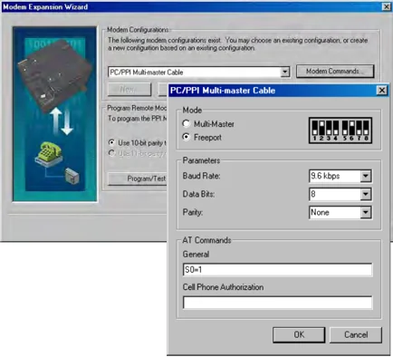
Figure 7-28 Modem Expansion Wizard - Sending Modem Command in Freeport Mode
While configuring the RS-232/PPI Multi-Master cable with STEP 7-Micro/WIN, you must connect the RS-485 connector to an S7-200 CPU. This is the source of the 24V power required for the cable to operate. Be sure to supply power to the S7-200 CPU.
After exiting the STEP 7-Micro/WIN configuration of the RS-232/PPI Multi-Master cable, disconnect the cable from the PC and connect it to the modem. Power cycle both the modem and the cable. You are now ready to use the cable for remote operation in a PPI multi-master network.
Tip
Your modem must be at the factory default settings for use with a PPI Multi-Master cable.
Using a Telephone Modem with the RS-232/PPI Multi-Master Cable
You can use an RS-232/PPI Multi-Master cable to connect the RS-232 communications port of a modem to an S7-200 CPU. See Figure 7-29.
- Switches 1, 2, and 3 set the baud rate.
- Switch 5 selects PPI or PPI/Freeport mode.
- Switch 6 select either Local (equivalent to the Data Communications Equipment - DCE) or remote (equivalent to Data Terminal Equipment - DTE) mode.
- Switch 7 selects either 10-bit or 11-bit PPI protocol.
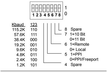
Figure 7-29 Settings for the RS-232/PPI Multi-Master Cable
Switch 5 selects operation in PPI mode or in PPI/Freeport mode. If you are using STEP 7-Micro/WIN to communicate with the S7-200 through modems, select PPI mode (switch 5 = 1). Otherwise, select PPI/Freeport mode (switch 5 = 0).
Switch 7 of the RS-232/PPI Multi-Master cable selects either a 10-bit or 11-bit mode for PPI/Freeport mode. Use switch 7 only when the S7-200 is connected to STEP 7-Micro/WIN with a modem in PPI/Freeport mode. Otherwise, set switch 7 for 11-bit mode to ensure proper operation with other devices.
Switch 6 of the RS-232/PPI Multi-Master cable allows you to set the RS-232 port of the cable to either Local (DCE) or Remote (DTE) mode.
- If you are using the RS-232/PPI Multi-Master cable with STEP 7-Micro/WIN or if the RS-232/PPI Multi-Master cable is connected to a computer, set the RS-232/PPI Multi-Master cable to Local (DCE) mode.
- If you are using the RS-232/PPI Multi-Master cable with a modem (which is a DCE device), set the RS-232/PPI Multi-Master cable to Remote (DTE) mode.
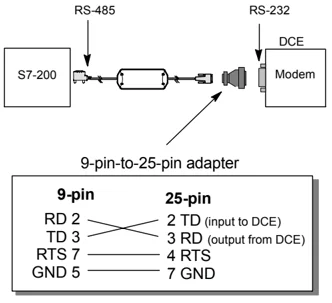
Figure 7-30 Pin Assignments for Adapters
This eliminates the need to install a null modem adapter between the RS-232/PPI Multi-Master cable and the modem. Depending on the connector on the modem, you might still need to use a 9-pin-to-25-pin adapter.
Figure 7-30 shows the pin assignment for a common modem adapter.
See Appendix A for more information about the RS-232/PPI Multi-Master cable. The pin numbers and functions for the RS-485 and RS-232 ports of the RS-232/PPI Multi-Master cable in Local (DCE) mode are shown in Table A-69. Table A-70 shows the pin numbers and functions for the RS-485 and RS-232 ports of the RS-232/PPI Multi-Master cable in Remote (DTE) mode. The RS-232/PPI Multi-Master cable supplies RTS only when it is in Remote (DTE) mode.
Using a Radio Modem with the RS-232/PPI Multi-Master Cable
You can use an RS-232/PPI Multi-Master cable to connect the RS-232 communications port of a radio modem to an S7-200 CPU. However, operation with radio modems is not the same as it is with telephone modems.
PPI Mode
With the RS-232/PPI Multi-Master cable set for PPI mode (switch 5 = 1), you would normally select remote mode (switch 6 = 1) for operation with a modem. However, selecting the remote mode causes the cable to send the character string 'AT' and wait for the modem to reply with 'OK' on each power up. While telephone modems use this sequence to establish the baud rate, radio modems do not generally accept AT commands.
Therefore, for operation with radio modems you must select local mode (switch 6 = 0) and use a null modem adapter between the RS-232 connector of the cable and the RS-232 port on your radio modem. Null modem adapters are available in either 9-pin-to-9 pin or 9-pin-to-25 pin configurations.
Configure the radio modem to operate at 9.6, 19.2, 38.4, 57.6 or 115.2 kbaud. The RS-232/PPI Multi-Master cable will automatically adjust to any one of these baud rates on the first character transmitted by the radio modem.
PPI/Freeport Mode
With the RS-232/PPI Multi-Master cable set for PPI/Freeport mode (switch 5 = 0), select remote mode (switch 6 = 1) for operation with a radio modem. Configure the cable so that it will not send any AT commands to setup the modem.
Switches 1, 2, and 3 on the RS-232/PPI Multi-Master cable set the baud rate. See Figure 7-29. Select the baud rate setting that corresponds to the baud rate of the PLC and the radio modem.
232
Advanced Topics
Optimizing the Network Performance
The following factors affect network performance (with baud rate and number of masters having the greatest effect):
☐ Baud rate: Operating the network at the highest baud rate supported by all devices has the greatest effect on the network.
☐ Number of masters on the network: Minimizing the number of masters on a network also increases the performance of the network. Each master on the network increases the overhead requirements of the network; having fewer masters lessens the overhead.
☐ Selection of master and slave addresses: The addresses of the master devices should be set so that all of the masters are at sequential addresses with no gaps between addresses. Whenever there is an address gap between masters, the masters continually check the addresses in the gap to see if there is another master wanting to come online. This checking requires time and increases the overhead of the network. If there is no address gap between masters, no checking is done and so the overhead is minimized. You can set the slave addresses to any value without affecting network performance, as long as the slaves are not between masters. Slaves between masters increase the network overhead in the same way as having address gaps between masters.
☐ Gap update factor (GUF): Used only when an S7-200 CPU is operating as a PPI master, the GUF tells the S7-200 how often to check the address gap for other masters. You use STEP 7-Micro/WIN to set the GUF in the CPU configuration for a CPU port. This configures the S7-200 to check address gaps only on a periodic basis. For GUF=1, the S7-200 checks the address gap every time it holds the token; for GUF=2, the S7-200 checks the address gap once every two times it holds the token. If there are address gaps between masters, a higher GUF reduces the network overhead. If there are no address gaps between masters, the GUF has no effect on performance. Setting a large number for the GUF causes long delays in bringing masters online, because the addresses are checked less frequently. The default GUF setting is 10.
☐ Highest station address (HSA): Used only when an S7-200 CPU is operating as a PPI master, the HSA defines the highest address at which a master should look for another master. You use STEP 7-Micro/WIN to set the HSA in the CPU configuration for a CPU port. Setting an HSA limits the address gap which must be checked by the last master (highest address) in the network. Limiting the size of the address gap minimizes the time required to find and bring online another master. The highest station address has no effect on slave addresses: masters can still communicate with slaves which have addresses greater than the HSA. As a general rule, set the highest station address on all masters to the same value. This address should be greater than or equal to the highest master address. The default value for the HSA is 31.
Calculating the Token Rotation Time for a Network
In a token-passing network, the only station that can initiate communications is the station that holds the token. The token rotation time (the time required for the token to be circulated to each of the masters in the logical ring) measures the performance of your network.
Figure 7-31 provides a sample network as an example for calculating the token rotation time for a multiple-master network. In this example, the TD 200 (station 3) communicates with the CPU 222 (station 2), the TD 200 (station 5) communicates with the CPU 222 (station 4), and so on. The two CPU 224 modules use the Network Read and Network Write instructions to gather data from the other S7-200s: CPU 224 (station 6) sends messages to stations 2, 4, and 8, and the CPU 224 (station 8) sends messages to stations 2, 4, and 6. In this network, there are six master stations (the four TD 200 units and the two CPU 224 modules) and two slave stations (the two CPU 222 modules).
Programming Tips Refer to the Programming Tips on the documentation CD for a discussion about token rotation. See Tip 42.
CPU 222 Station 2 CPU 222 Station 4 CPU 224 Station 6 CPU 224 Station 8 TD 200 Station 9 TD 200 Station 7 TD 200 Station 5 TD 200 Station 3
 Figure 7-31 Example of a Token-Passing Network
In order for a master to send a message, it must hold the token. For example: When station 3 has the token, it initiates a request message to station 2 and then it passes the token to station 5. Station 5 then initiates a request message to station 4 and then passes the token to station 6. Station 6 then initiates a message to station 2, 4, or 8, and passes the token to station 7. This process of initiating a message and passing the token continues around the logical ring from station 3 to station 5, station 6, station 7, station 8, station 9, and finally back to station 3. The token must rotate completely around the logical ring in order for a master to be able to send a request for information. For a logical ring of six stations, sending one request message per token hold to read or write one double-word value (four bytes of data), the token rotation time is approximately 900 ms at 9600 baud. Increasing the number of bytes of data accessed per message or increasing the number of stations increases the token rotation time.
The token rotation time is determined by how long each station holds the token. You can determine the token rotation time for your multiple-master network by adding the times that each master holds the token. If the PPI master mode has been enabled (under the PPI protocol on your network), you can send messages to other S7-200s by using the Network Read and Network Write instructions with the S7-200. If you send messages using these instructions, you can use the following formula to calculate the approximate token rotation time, based on the following assumptions: each station sends one request per token hold, the request is either a read or write request for consecutive data locations, there is no conflict for use of the one communications buffer in the S7-200, and there is no S7-200 that has a scan time longer than about 10 ms.
Token hold time ($T_{hold}$) = (128 overhead + n data char) x 11 bits/char x 1/baud rate Token rotation time ($T_{rot}$) = $T_{hold}$ of master 1 + $T_{hold}$ of master 2 + ... + $T_{hold}$ of master m where n is the number of data characters (bytes) m is the number of masters
The following equations calculate the rotation times (one "bit time" equals the duration of one signaling period) for the example shown in Figure 7-31:
T (token hold time) = (128 + 4 char) x 11 bits/char x 1/9600 bit times/s = 151.25 ms per master T (token rotation time) = 151.25 ms per master ≤ 6 masters = 907.5 ms
Tip SIMATIC NET COM PROFIBUS software provides an analyzer to determine network performance.
234
Comparing Token Rotation Times
Table 7-12 shows comparisons of the token rotation time versus the number of stations, amount of data, and the baud rate. The times are figured for a case where you use the Network Read and Network Write instructions with the S7-200 CPU or other master devices.
Table 7-12 Token Rotation Time (in Seconds)
| Baud Rate | Bytes Transferred | Number of Masters | |||||||||
|---|---|---|---|---|---|---|---|---|---|---|---|
| 2 | 3 | 4 | 5 | 6 | 7 | 8 | 9 | 10 | |||
| 9.6 kbaud | 1 | 0.30 | 0.44 | 0.59 | 0.74 | 0.89 | 1.03 | 1.18 | 1.33 | 1.48 | |
| 16 | 0.33 | 0.50 | 0.66 | 0.83 | 0.99 | 1.16 | 1.32 | 1.49 | 1.65 | ||
| 19.2 kbaud | 1 | 0.15 | 0.22 | 0.30 | 0.37 | 0.44 | 0.52 | 0.59 | 0.67 | 0.74 | |
| 16 | 0.17 | 0.25 | 0.33 | 0.41 | 0.50 | 0.58 | 0.66 | 0.74 | 0.83 | ||
| 187.5 kbaud | 1 | 0.009 | 0.013 | 0.017 | 0.022 | 0.026 | 0.030 | 0.035 | 0.039 | 0.043 | |
| 16 | 0.011 | 0.016 | 0.021 | 0.026 | 0.031 | 0.037 | 0.042 | 0.047 | 0.052 |
Understanding the Connections That Link the Network Devices
Network devices communicate through individual connections, which are private links between the master and slave devices. As shown in Figure 7-32, the communications protocols differ in how the connections are handled:
- The PPI protocol utilizes one shared connection among all of the network devices.
- The PPI Advanced, MPI, and PROFIBUS protocols utilize separate connections between any two devices communicating with each other.
When using PPI Advanced, MPI, or PROFIBUS, a second master cannot interfere with a connection that has been established between a master and a slave. S7-200 CPUs and EM 277s always reserve one connection for STEP 7–Micro/WIN and one connection for HMI devices. Other master devices cannot use these reserved connections. This ensures that you can always connect at least one programming station and at least one HMI device to the S7-200 CPU or EM 277 when the master is using a protocol that supports connections, such as PPI Advanced.
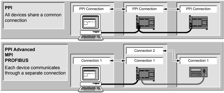
Figure 7-32 Managing the Communications Connections