PTOx_RUN Subroutine
The PTOx_RUN subroutine (Run Profile) commands the PLC to execute the motion operation in a specific profile stored in the configuration/profile table.
Turning on the EN bit enables the subroutine. Ensure that the EN bit stays on until the Done bit signals that the execution of the subroutine has completed.
Turning on the START parameter initiates execution of the profile. For each scan when the START parameter is on and the PTO is not currently active, the instruction activates the PTO. To ensure that only one command is sent, use an edge detection element to pulse the START parameter on.
The Profile parameter contains the number or the symbolic name for the motion profile.
Turning on the Abort parameter commands the Position module to stop the current profile and decelerate until the motor comes to a stop.
The Done parameter turns on when the module completes this instruction.
The Error parameter contains the result of this instruction. See Table 9-7 for definitions of the error codes.
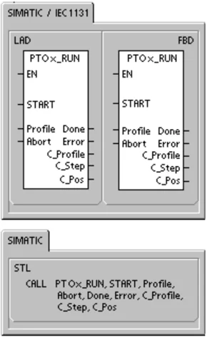
The C_Profile parameter contains the profile currently being executed by the Position module.
The C_Step parameter contains the step of the profile currently being executed.
The C_Pos parameter contains the current position of the module as the number of pulses if the HSC was enabled in the wizard. Otherwise the current position is always 0.
Table 9-4 Parameters for the PTOx_RUN Instruction
PTOx_MAN Subroutine
The PTOx_MAN subroutine (Manual Mode) puts the PTO output in manual mode. This allows the motor to be started, stopped and run at different speeds within the range from Start/Stop speed through Maximum speed as specified in the wizard. While the PTOx_MAN subroutine is enabled, no other PTOx_RUN or PTOx_ADV instructions should be executed.
Enabling the RUN (Run/Stop) parameter commands the PTO to accelerate to the specified speed (Speed parameter). You can change the value for the Speed parameter while the motor is running. Disabling the RUN parameter commands the PTO to decelerate until the motor comes to a stop.
The Speed parameter determines the speed when RUN is enabled. The speed will be clamped to Start/Stop or Maximum for values of the Speed parameter outside this range. The speed is a DINT value for pulses/second. You can change this parameter while the motor is running.
The Error parameter contains the result of this instruction. See Table 9-7 for definitions of the error codes.
The C_Pos parameter contains the current position of the module as the number of pulses if the HSC was enabled in the wizard. Otherwise the current position is always 0.
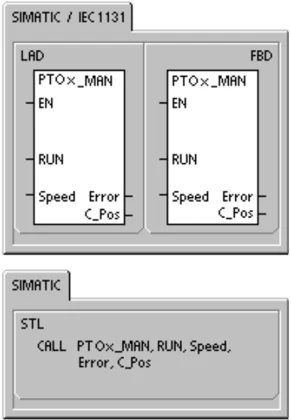
Table 9-5 Parameters for the PTOx_MAN Instruction \begin{tabular}{|l|l|l|} \hline Inputs/Outputs & Data Types & Operands \ \hline RUN & BOOL & I, Q, V, M, SM, S, T, C, L, Power Flow \ \hline SPEED & DINT & ID, QD, VD, MD, SMD, SD, LD, AC, *VD, *AC, *LD, Constant \ \hline Error & BYTE & IB, QB, VB, MB, SMB, SB, LB, AC, *VD, *AC, *LD \ \hline C_Pos & DINT & ID, QD, VD, MD, SMD, SD, LD, AC, *VD, *AC, *LD \ \hline \end{tabular}
Tip The PTO may not react to small changes in the Speed parameter, especially if the configured acceleration or deceleration time is short and the difference between the configured maximum speed and start/stop speed is large.
PTOx_LDPOS Instruction
The PTOx_LDPOS instruction (Load Position) changes the current position value of the PTO pulse counter to a new value. You can also use this instruction to establish a new zero position for any move command.
Turning on the EN bit enables the instruction. Ensure that the EN bit stays on until the Done bit signals that the execution of the instruction has completed.
Turning on the START parameter loads a new position into the PTO pulse counter. For each scan when the START parameter is on and the PTO is not currently busy, the instruction loads a new position into the PTO pulse counter. To ensure that only one command is sent, use an edge detection element to pulse the START parameter on.
The New_Pos parameter provides the new value to replace the current position value that is reported. The position value is expressed as a number of pulses.
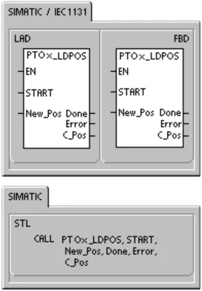
The Done parameter turns on when the module completes this instruction.
The Error parameter contains the result of this instruction. See Table 9-7 for definitions of the error codes.
The C_Pos parameter contains the current position of the module as the number of pulses if the HSC was enabled in the wizard. Otherwise the current position is always 0.
Table 9-6 Parameters for the PTOx_LDPOS Instruction \begin{tabular}{|l|l|l|} \hline Inputs/Outputs & Data Types & Operands \ \hline START & BOOL & I, Q, V, M, SM, S, T, C, L, Power Flow \ \hline New_Pos, C_Pos & DINT & ID, QD, VD, MD, SMD, SD, LD, AC, *VD, *AC, *LD \ \hline Done & BOOL & I, Q, V, M, SM, S, T, C, L \ \hline Error & BYTE & IB, QB, VB, MB, SMB, SB, LB, AC, *VD, *AC, *LD \ \hline \end{tabular}
PTOx ADV Subroutine
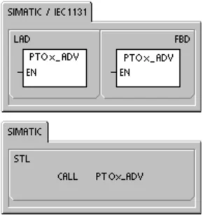
The PTOx_ADV subroutine stops the current continuous motion profile and advances the number of pulses specified in the wizard profile definition. This subroutine is created if you have specified at least one single speed continuous rotation with the PTOx_ADV option enabled in the Position Control Wizard.
Error Codes for the PTO Instructions
Table 9-7 PTO Instruction Error Codes \begin{tabular}{|l|l|} \hline Error Code & Description \ \hline 0 & No error, normal completion \ \hline 1 & Immediate STOP issued during move. STOP command completed successfully \ \hline 2 & Decelerated STOP issued during move. STOP command completed successfully \ \hline 3 & Execution error detected in the pulse generator or in format of the PTO table \ \hline 127 & An ENO error was encountered. Check PLC information for description on non-fatal error \ \hline 128 & Busy. Another PTO operation is already in process \ \hline 129 & Both the Immediate STOP and Decelerated STOP commands were enabled at the same time, resulting in an immediate STOP \ \hline 130 & The PTO instruction is currently being commanded to STOP \ \hline 132 & Requested profile number is out of range \ \hline \end{tabular}
264
Features of the Position Module
The Position module provides the functionality and performance that you need for single-axis, open-loop position control:
Provides high-speed control, with a range from 20 pulses per second up to 200,000 pulses per second
Supports both jerk (S curve) or linear acceleration and deceleration
Provides a configurable measuring system that allows you to enter data either as engineering units (such as inches or centimeters) or as a number of pulses
Provides configurable backlash compensation
Supports absolute, relative, and manual methods of position control
Provides continuous operation
Provides up to 25 motion profiles, with up to 4 speed changes per profile
Provides four different reference-point seek modes, with a choice of the starting seek direction and the final approach direction for each sequence
Provides removable field wiring connectors for easy installation and removal
 Figure 9-9 EM 253 Position Module
You use STEP 7-Micro/WIN to create all of the configuration and profile information used by the Position module. This information is downloaded to the S7-200 with your program blocks. Because all the information required for position control is stored in the S7-200, you can replace a Position module without having to reprogram or reconfigure the module.
The S7-200 reserves 8 bits of the process image output register (Q memory) for the interface to the Position module. Your application program in the S7-200 uses these bits to control the operation of the Position module. These 8 output bits are not connected to any of the physical field outputs of the Position module.
The Position module provides five digital inputs and four digital outputs that provide the interface to your motion application. See Table 9-8. These inputs and outputs are local to the Position module. Appendix A provides the detailed specifications for the Position module and also includes wiring diagrams for connecting the Position module to some of the more common motor driver/amplifier units.
Table 9-8 Inputs and Outputs of the Position Module
Programming the Position Module
STEP 7-Micro/WIN provides easy-to-use tools for configuring and programming the Position module. Simply follow these steps:
-
Configure the Position module. STEP 7-Micro/WIN provides a Position Control wizard for creating the configuration/profile table and the position instructions. See Configuring the Position Module on page 270 for information about configuring the Position module.
-
Test the operation of the Position Module. STEP 7-Micro/WIN provides an EM 253 control panel for testing the wiring of the inputs and outputs, the configuration of the Position module, and the operation of the motion profiles. See page 290 for information about the EM 253 control panel.
-
Create the program to be executed by the S7-200. The Position Control wizard automatically creates the position instructions that you insert into your program. See page 273 for information about the position instructions. Insert the following instructions into your program:
- To enable the Position module, insert a POSx_CTRL instruction. Use SM0.0 (Always On) to ensure that this instruction is executed every scan.
- To move the motor to a specific location, use a POSx_GOTO or a POSx_RUN instruction. The POSx_GOTO instruction move to a location specified by the inputs from your program. The POSx_RUN instruction executes the motion profiles you configured with the Position Control wizard.
- To use absolute coordinates for your motion, you must establish the zero position for your application. Use the a POSx_RSEEK or a POSx_LDPOS instruction to establish the zero position.
- The other instructions that are created by the Position Control wizard provide functionality for typical applications and are optional for your specific application.
-
Compile your program and download the system block, data block, and program block to the S7-200.
Tip Refer to Appendix A for information about connecting the Position module to several common stepper motor controllers.
Tip To match the default settings in the Position Control wizard, set the DIP switches on the stepper motor controller to 10,000 pulses per revolution.
Configuring the Position Module
You must create a configuration/profile table for the Position module in order for the module to control your motion application. The Position Control wizard makes the configuration process quick and easy by leading you step-by-step through the configuration process. Refer to the Advanced Topics on page 294 for detailed information about the configuration/profile table.
The Position Control wizard also allows you to create the configuration/profile table offline. You can create the configuration without being connected to an S7-200 CPU with a Position module installed.
To run the Position Control wizard, your project must have been compiled and set to symbolic addressing mode.
To start the Position Control wizard, either click the Tools icon in the navigation bar and then double-click the Position Control Wizard icon, or select the Tools> Position Control Wizard menu command.
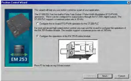
Figure 9-10 Position Control Wizard
To configure the Position Control Module use the Position Control wizard. Select the option to configure the EM 253 Position Control Module.
Enter location of module
Specify the module slot position (module 0 to module 6). If STEP 7-Micro/WIN is connected to the PLC, you only have to click the Read Modules button. For an S7-200 CPU with firmware prior to version 1.2, the module must be installed next to the CPU.
Select type of measurement
Select the measurement system. You can select either engineering units or pulses. If you select pulses, no other information is required. If you select engineering units, the number of pulses required to produce one revolution of the motor (refer to the data sheet for your motor or drive), the base unit of measurement (such as inch, foot, millimeter, or centimeter), and the distance traveled in one revolution of the motor.
STEP 7-Micro/WIN provides an EM253 Control Panel that allows you to modify the number of units per revolution after the Position module has been configured.
If you change the measurement system later, you must delete the entire configuration including any instructions generated by the Position Control wizard. You must then enter your selections consistent with the new measurement system.
Edit default input and output configuration
To change or view the default configuration of the integrated inputs/outputs select the Advanced Options button.
Use the Input Active Levels tab to select the active level (High or Low). When the level is set to High, a logic 1 is read when current is flowing in the input. When the level is set to Low, a logic 1 is read when there is no current flow in the input. A logic 1 level is always interpreted as meaning the condition is active. The LEDs are illuminated when current flows in the input, regardless of activation level. (Default = active high)
Use the Input Filter Times tab to select the filter time constant (0.20 ms to 12.80 ms) for the STP, RPS, LMT+, and LMT- inputs. Increasing the filter time constant eliminates more noise, but it also slows down the response time to a signal state change. (Default = 6.4 ms)
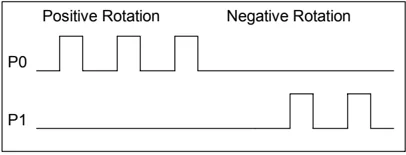
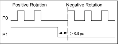
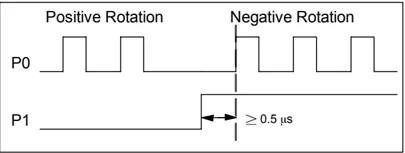
Use the Pulse and Directional Outputs tab to select the polarity of the outputs and to select the direction control method. See Figures 9-11 and 9-12 to see the effects of polarity and direction control method selections.
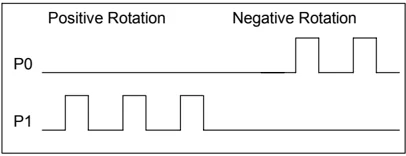
Figure 9-11 Rotation Options for Positive Polarity

Figure 9-12 Rotation Options for Negative Polarity
Warning Control devices can fail in unsafe conditions, and can result in unpredictable operation of controlled equipment. Such unpredictable operations could result in death or serious personal injury, and/or equipment failure. The limit and stop functions in the Position Module are electronic logic implementations that do not provide the level of protection provided by electromechanical controls. Consider using an emergency stop function, electromechanical overrides, or redundant safeguards that are independent of the Position module and the S7-200 CPU.
Configure response of module to physical inputs Next, select the module response to the LMT+, the LMT-, and the STP inputs. Use the drop down box to select: no action (ignore the input condition), decelerate to a stop (default), or immediate stop.
Enter maximum start and stop speed Enter the maximum speed (MAX_SPEED) and Start/Stop Speed (SS_SPEED) for your application
268
Open Loop Motion Control with the S7-200 Chapter 9
Enter jog parameters
Next, enter the JOG_SPEED and the JOG_INCREMENT values.
JOG_SPEED: The JOG_SPEED (Jog speed for the motor) is the maximum speed that can be obtained while the JOG command remains active.
JOG_INCREMENT: Distance that the tool is moved by a momentary JOG command.
Figure 9-13 shows the operation of the Jog command. When the Position module receives a Jog command, it starts a timer. If the Jog command is terminated before 0.5 seconds has elapsed, the Position module moves the tool the amount specified in the JOG_INCREMENT at the speed defined by SS_SPEED. If the Jog command is still active when the 0.5 seconds have elapsed, the Position module accelerates to the JOG_SPEED. Motion continues until the Jog command is terminated. The Position module then performs a decelerated stop. You can enable the Jog command either from the EM 253 control panel or with a position instruction.
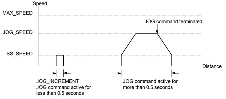
Figure 9-13 Representation of a JOG Operation
Enter acceleration time
Enter the acceleration and deceleration times in the edit boxes
Enter jerk time
For single step moves enter the jerk time compensation. This provides smoother position control by reducing the jerk (rate of change) in acceleration and deceleration parts of the motion profile. See Figure 9-14.
Jerk time compensation is also known as "S curve profiling." This compensation is applied equally to the beginning and ending portions of both the acceleration and deceleration curve. Jerk compensation is not applied to the initial and final step between zero speed and SS_SPEED.
269
You specify the jerk compensation by entering a time value (JERK_TIME). This is the time required for acceleration to change from zero to the maximum acceleration rate. A longer jerk time yields smoother operation with a smaller increase in total cycle time than would be obtained by decreasing the ACCEL_TIME and DECEL_TIME. A value of zero indicates that no compensation is to be applied.
(Default = 0 ms)
 Figure 9-14 Jerk Compensation
Tip A good first value for JERK_TIME is 40% of ACCEL_TIME.
Configure reference point and seek parameters
Select using a reference point or not using a reference point for your application.
- If your application requires that movements start from or be referenced to an absolute position, you must establish a reference point (RP) or zero position that fixes the position measurements to a known point on the physical system.
- If a reference point is used, you will want to define a way to automatically relocate the reference point. The process of automatically locating the reference point is called Reference Point Seek. Defining the Reference Point Seek process requires two steps in the wizard.
Enter the Reference Point seek speeds (a fast seek speed and a slow seek speed). Define the initial seek direction and the final reference point approach direction. Use the advanced RP Options button to enter Reference Point Offset and backlash compensation values.
RP_FAST is the initial speed the module uses when performing an RP seek command. Typically, the RP_FAST value is approximately 2/3 of the MAX_SPEED value.
RP_SLOW is the speed of the final approach to the RP. A slower speed is used on approach to the RP, so as not to miss it. Typically, the RP_SLOW value is the SS_SPEED value.
RP_SEEK_DIR is the initial direction for the RP seek operation. Typically, this is the direction from the work zone to the vicinity of the RP. Limit switches play an important role in defining the region that is searched for the RP. When performing a RP seek operation, encountering a limit switch can result in a reversal of the direction, which allows the search to continue. (Default = Negative)
RP_APPR_DIR is the direction of the final approach to the RP. To reduce backlash and provide more accuracy, the reference point should be approached in the same direction used to move from the RP to the work zone. (Default = Positive)
270
The Position Control wizard provides advanced reference point options that allow you to specify an RP offset (RP_OFFSET), which is the distance from the RP to the zero position. See Figure 9-15.
RP_OFFSET: Distance from the RP to the zero position of the physical measuring system. Default = 0
Backlash compensation: Distance that the motor must move to eliminate the slack (backlash) in the system on a direction change. Backlash compensation is always a positive value. Default = 0
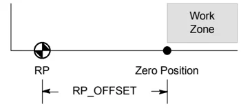
Figure 9-15 Relationship Between RP and Zero Position
Choose a Reference Point search sequence.
The Position module provides a reference point switch (RPS) input that is used when seeking the RP. The RP is identified by a method of locating an exact position with respect to the RPS. The RP can be centered in the RPS Active zone, the RP can be located on the edge of the RPS Active zone, or the RP can be located a specified number of zero pulse (ZP) input transitions from the edge of the RPS Active zone.
You can configure the sequence that the Position module uses to search for the reference point. Figure 9-16 shows a simplified diagram of the default RP search sequence. You can select the following options for the RP search sequence:
RP Seek mode 0: Does not perform a RP seek sequence
RP Seek mode 1: The RP is where the RPS input goes active on the approach from the work zone side. (Default)
RP Seek mode 2: The RP is centered within the active region of the RPS input.
RP Seek mode 3: The RP is located outside the active region of the RPS input. RP_Z_CNT specifies how many ZP (Zero Pulse) input counts should be received after the RPS becomes inactive.
RP Seek mode 4: The RP is generally within the active region of the RPS input. RP_Z_CNT specifies how many ZP (Zero Pulse) input counts should be received after the RPS becomes active.
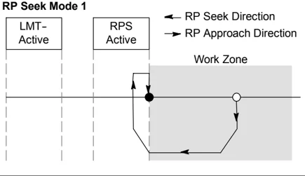
Figure 9-16 Default RP Search Sequence (Simplified)
Tip The RPS Active region (which is the distance that the RPS input remains active) must be greater than the distance required to decelerate from the RP_FAST speed to the RP_SLOW speed. If the distance is too short, the Position module generates an error.
S7-200 Programmable Controller System Manual
Command byte
Next enter the Q byte address for the command byte. The command byte is the address of the 8 digital outputs reserved in the process image register for the interface to the Position Module. See Figure 4-11 in Chapter 4 for a description of the I/O numbering.
Defining the motion profile
In the motion profile definition screen, click the new profile button to enable defining the profile. Choose the desired mode of operation.
For an absolute position profile: Fill in the target speed and the ending position. You may then click the plot step button to see a graphical representation of the move. If more than one step is needed, click the new step button and fill in the step information as required.
For a relative position profile: Fill in the target speed and the ending position. You may then click the plot step button to see a graphical representation of the move. If more than one step is needed, click the new step button and fill in the step information as required.
For a single-speed, continuous rotation: Enter the single speed value in the edit box. Select the direction of rotation If you wish to terminate the single speed, continuous rotation move using the RPS input, click the check box.
For a two-speed, continuous rotation: Enter the target speed value when RPS is high in the edit box. Enter the target speed value when RPS is low in the edit box. Select the direction of rotation
Define as many profiles and steps as you need to perform the desired movement.
Finish the configuration
After you have configured the operation of the Position module, you simply click Finish, and the Position Control wizard performs the following tasks:
Inserts the module configuration and profile table into the data block for your S7-200 program
Creates a global symbol table for the motion parameters
Adds the motion instruction subroutines into the project program block for you to use in your application
You can run the Position Control wizard again in order to modify any configuration or profile information.
Tip Because the Position Control wizard makes changes to the program block, the data block and the system block, be sure to download all three blocks to the S7-200 CPU. Otherwise, the Position module might not have all the program components that it needs for proper operation.
272
Instructions Created by the Position Control Wizard for the Position Module
The Position Control wizard makes controlling the Position module easier by creating unique instruction subroutines based on the position of the module and configuration options you selected. Each position instruction is prefixed with a "POSx_" where x is the module location. Because each position instruction is a subroutine, the 11 position instructions use 11 subroutines.
Tip The position instructions increase the amount of memory required for your program by up to 1700 bytes. You can delete unused position instructions to reduce the amount of memory required. To restore a deleted position instruction, simply run the Position Control wizard again.
Guidelines for Using the Position Instructions
You must ensure that only one position instruction is active at a time.
You can execute the POSx_RUN and POSx_GOTO from an interrupt routine. However, it is very important that you do not attempt to start an instruction in an interrupt routine if the module is busy processing another command. If you start an instruction in an interrupt routine, then you can use the outputs of the POSx_CTRL instruction to monitor when the Position module has completed the movement.
The Position Control wizard automatically configures the values for the speed parameters (Speed and C_Speed) and the position parameters (Pos or C_Pos) according to the measurement system that you selected. For pulses, these parameters are DINT values. For engineering units, the parameters are REAL values for the type of unit that you selected. For example: selecting centimeters (cm) stores the position parameters as REAL values in centimeters and stores the speed parameters as REAL values in centimeters per second (cm/sec).
The following position instructions are required for specific position control tasks:
- Insert the POSx_CTRL instruction in your program and use the SM0.0 contact to execute it every scan.
- To specify motion to an absolute position, you must first use either an POSx_RSEEK or a POSx_LDPOS instruction to establish the zero position.
- To move to a specific location, based on inputs from your program, use the POSx_GOTO instruction.
- To run the motion profiles you configured with the Position Control wizard, use the POSx_RUN instruction.
The other position instructions are optional.
POSx_CTRL Instruction
The POSx_CTRL instruction (Control) enables and initializes the Position module by automatically commanding the Position module to load the configuration/profile table each time the S7-200 changes to RUN mode.
Use this instruction only once in your project, and ensure that your program calls this instruction every scan. Use SM0.0 (Always On) as the input for the EN parameter.
The MOD_EN parameter must be on to enable the other position instructions to send commands to the Position module. If the MOD_EN parameter turns off, then the Position module aborts any command that is in progress.
The output parameters of the POSx_CTRL instruction provide the current status of the Position module.
The Done parameter turns on when the Position module completes any instruction.
The Error parameter contains the result of this instruction. See Table 9-20 for definitions of the error codes.
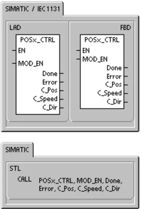
The C_Pos parameter is the current position of the module. Based of the units of measurement, the value is either a number of pulses (DINT) or the number of engineering units (REAL).
The C_Speed parameter provides the current speed of the module. If you configured the measurement system for the Position module for pulses, C_Speed is a DINT value containing the number of pulses/second. If you configured the measurement system for engineering units, C_Speed is a REAL value containing the selected engineering units/second (REAL).
The C_Dir parameter indicates the current direction of the motor.
Table 9-9 Parameters for the POSx_CTRL Instruction \begin{tabular}{|l|l|l|} \hline Inputs/Outputs & Data Type & Operands \ \hline MOD_EN & BOOL & I, Q, V, M, SM, S, T, C, L, Power Flow \ \hline Done, C_Dir & BOOL & I, Q, V, M, SM, S, T, C, L \ \hline Error & BYTE & IB, QB, VB, MB, SMB, SB, LB, AC, *VD, *AC, *LD \ \hline C_Pos, C_Speed & DINT, REAL & ID, QD, VD, MD, SMD, SD, LD, AC, *VD, *AC, *LD \ \hline \end{tabular}
Tip The Position module reads the configuration/profile table only at power-up or when commanded to load the configuration.
- If you use the Position Control wizard to modify the configuration, then the POSx_CTRL instruction automatically commands the Position module to load the configuration/profile table every time the S7-200 CPU changes to RUN mode.
- If you use the EM 253 Control Panel to modify the configuration, clicking the Update Configuration button commands the Position module to load the new configuration/profile table.
- If you use another method to modify the configuration, then you must also issue a Reload the Configuration command to the Position module to load the configuration/profile table. Otherwise, the Position module continues to use the old configuration/profile table.
POSx_MAN Instruction
The POSx_MAN instruction (Manual Mode) puts the Position module into manual mode. This allows the motor to be run at different speeds or to be jogged in a positive or negative direction. While the POSx_MAN instruction is enabled, only the POSx_CTRL and POSx_DIS instructions are allowed.
You can enable only one of the RUN, JOG_P, or JOG_N inputs at a time.
Enabling the RUN (Run/Stop) parameter commands to the Position module to accelerate to the specified speed (Speed parameter) and direction (Dir parameter). You can change the value for the Speed parameter while the motor is running, but the Dir parameter must remain constant. Disabling the RUN parameter commands the Position module to decelerate until the motor comes to a stop.
Enabling the JOG_P (Jog Positive Rotation) or the JOG_N (Jog Negative Rotation) parameter commands the Position module to jog in either a positive or negative direction. If the JOG_P or JOG_N parameter remains enabled for less than 0.5 seconds, the Position module issues pulses to travel the distance specified in JOG_INCREMENT. If the JOG_P or JOG_N parameter remains enabled for 0.5 seconds or longer, the motion module begins to accelerate to the specified JOG_SPEED.
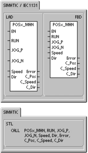
The Speed parameter determines the speed when RUN is enabled. If you configured the measuring system of the Position module for pulses, the speed is a DINT value for pulses/second. If you configured the measuring system of the Position module for engineering units, the speed is a REAL value for units/second. You can change this parameter while the motor is running.
Tip The Position module may not react to small changes in the Speed parameter, especially if the configured acceleration or deceleration time is short and the difference between the configured maximum speed and start/stop speed is large.
For more information refer to FAQ 22632118 on the Siemens Internet site at www.siemens.com/S7-200.
The Dir parameter determines the direction to move when RUN is enabled. You cannot change this value when the RUN parameter is enabled.
The Error parameter contains the result of this instruction. See Table 9-20 for definitions of the error codes.
The C_Pos parameter contains the current position of the module. Based of the units of measurement selected, the value is either a number of pulses (DINT) or the number of engineering units (REAL).
The C_Speed parameter contains the current speed of the module. Based of the units of measurement selected, the value is either the number of pulses/second (DINT) or the engineering units/second (REAL).
The C_Dir parameter indicates the current direction of the motor.
Table 9-10 Parameters for the POSx_MAN Instruction \begin{tabular}{|l|l|l|} \hline Inputs/Outputs & Data Type & Operands \ \hline RUN, JOG_P, JOG_N & BOOL & I, Q, V, M, SM, S, T, C, L, Power Flow \ \hline Speed & DINT, REAL & ID, QD, VD, MD, SMD, SD, LD, AC, *VD, *AC, *LD, Constant \ \hline Dir, C_Dir & BOOL & I, Q, V, M, SM, S, T, C, L \ \hline Error & BYTE & IB, QB, VB, MB, SMB, SB, LB, AC, *VD, *AC, *LD \ \hline C_Pos, C_Speed & DINT, REAL & ID, QD, VD, MD, SMD, SD, LD, AC, *VD, *AC, *LD \ \hline \end{tabular}
POSx_GOTO Instruction
The POSx_GOTO instruction commands the Position Module to go to a desired location.
Turning on the EN bit enables the instruction. Ensure that the EN bit stays on until the DONE bit signals that the execution of the instruction has completed.
Turning on the START parameter sends a GOTO command to the Position module. For each scan when the START parameter is on and the Position module is not currently busy, the instruction sends a GOTO command to the Position module. To ensure that only one GOTO command is sent, use an edge detection element to pulse the START parameter on.
The Pos parameter contains a value that signifies either the location to move (for an absolute move) or the distance to move (for a relative move). Based of the units of measurement selected, the value is either a number of pulses (DINT) or the engineering units (REAL).
The Speed parameter determines the maximum speed for this movement. Based of the units of measurement, the value is either a number of pulses/second (DINT) or the engineering units/second (REAL).
The Mode parameter selects the type of move: 0 - Absolute position 1 - Relative position 2 - Single-speed, continuous positive rotation 3 - Single-speed, continuous negative rotation
The Done parameter turns on when the Position module completes this instruction.
Turning on the Abort parameter commands the Position module to stop the current profile and decelerate until the motor comes to a stop.
The Error parameter contains the result of this instruction. See Table 9-20 for definitions of the error codes.
The C_Pos parameter contains current position of the module. Based of the units of measurement, the value is either a number of pulses (DINT) or the number of engineering units (REAL).
The C_Speed parameter contains the current speed of the module. Based of the units of measurement, the value is either a number of pulses/second (DINT) or the engineering units/second (REAL).
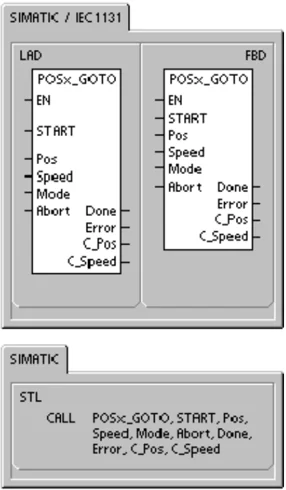
Table 9-11 Parameters for the POSx_GOTO Instruction
POSx_RUN Instruction
The POSx_RUN instruction (Run Profile) commands the Position module to execute the motion operation in a specific profile stored in the configuration/profile table.
Turning on the EN bit enables the instruction. Ensure that the EN bit stays on until the Done bit signals that the execution of the instruction has completed.
Turning on the START parameter sends a RUN command to the Position module. For each scan when the START parameter is on and the Position module is not currently busy, the instruction sends a RUN command to the Position module. To ensure that only one command is sent, use an edge detection element to pulse the START parameter on.
The Profile parameter contains the number or the symbolic name for the motion profile. You can also select the advanced motion commands (118 to 127). For information about the motion commands, see Table 9-26.
Turning on the Abort parameter commands the Position module to stop the current profile and decelerate until the motor comes to a stop.
The Done parameter turns on when the module completes this instruction.
The Error parameter contains the result of this instruction. See Table 9-20 for definitions of the error codes.
The C_Profile parameter contains the profile currently being executed by the Position module.
The C_Step parameter contains the step of the profile currently being executed.
The C_Pos parameter contains the current position of the module. Based of the units of measurement, the value is either a number of pulses (DINT) or the number of engineering units (REAL).
The C_Speed parameter contains the current speed of the module. Based of the units of measurement, the value is either a number of pulses/second (DINT) or the engineering units/second (REAL).
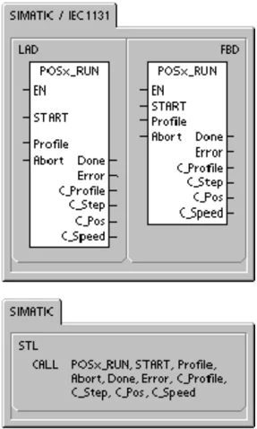
Table 9-12 Parameters for the POSx_RUN Instruction \begin{tabular}{|l|l|l|} \hline Inputs/Outputs & Data Type & Operands \ \hline START & BOOL & I, Q, V, M, SM, S, T, C, L, Power Flow \ \hline Profile & BYTE & IB, QB, VB, MB, SMB, SB, LB, AC, *VD, *AC, *LD, Constant \ \hline Abort, Done & BOOL & I, Q, V, M, SM, S, T, C, L \ \hline Error, C_Profile, C_Step & BYTE & IB, QB, VB, MB, SMB, SB, LB, AC, *VD, *AC, *LD \ \hline C_Pos, C_Speed & DINT, REAL & ID, QD, VD, MD, SMD, SD, LD, AC, *VD, *AC, *LD \ \hline \end{tabular}
POSx_RSEEK Instruction
The POSx_RSEEK instruction (Seek Reference Point Position) initiates a reference point seek operation, using the search method in the configuration/profile table. When the Position module locates the reference point and motion has stopped, the Position module loads the RP_OFFSET parameter value into the current position and generates a 50-millisecond pulse on the CLR output.
The default value for RP_OFFSET is 0. You can use the Position Control wizard, the EM253 Control Panel, or the POSx_LDOFF (Load Offset) instruction to change the RP_OFFSET value.
Turning on the EN bit enables the instruction. Ensure that the EN bit stays on until the Done bit signals that the execution of the instruction has completed.
Turning on the START parameter sends a RSEEK command to the Position module. For each scan when the START parameter is on and the Position module is not currently busy, the instruction sends a RSEEK command to the Position module. To ensure that only one command is sent, use an edge detection element to pulse the START parameter on.
The Done parameter turns on when the module completes this instruction.
The Error parameter contains the result of this instruction. See Table 9-20 for definitions of the error codes.
Table 9-13 Parameters for the POSx_RSEEK Instruction
 \begin{tabular}{|l|l|l|}
\hline
Inputs/Outputs & Data Type & Operands \
\hline
START & BOOL & I, Q, V, M, SM, S, T, C, L, Power Flow \
\hline
Done & BOOL & I, Q, V, M, SM, S, T, C, L \
\hline
Error & BYTE & IB, QB, VB, MB, SMB, SB, LB, AC, *VD, *AC, *LD \
\hline
\end{tabular}
POSx_LDOFF Instruction
The POSx_LDOFF instruction (Load Reference Point Offset) establishes a new zero position that is at a different location from the reference point position.
Before executing this instruction, you must first determine the position of the reference point. You must also move the machine to the starting position. When the instruction sends the LDOFF command, the Position module computes the offset between the starting position (the current position) and the reference point position. The Position module then stores the computed offset to the RP_OFFSET parameter and sets the current position to 0. This establishes the starting position as the zero position.
In the event that the motor loses track of its position (such as on loss of power or if the motor is repositioned manually), you can use the POSx_RSEEK instruction to re-establish the zero position automatically.
Turning on the EN bit enables the instruction. Ensure that the EN bit stays on until the Done bit signals that the execution of the instruction has completed.
Turning on the START parameter sends a LDOFF command to the Position module. For each scan when the START parameter is on and the Position module is not currently busy, the instruction sends a LDOFF command to the Position module. To ensure that only one command is sent, use an edge detection element to pulse the START parameter on.
The Done parameter turns on when the module completes this instruction.
The Error parameter contains the result of this instruction. See Table 9-20 on for definitions of the error codes.
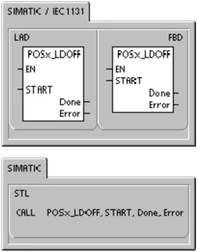
Table 9-14 Parameters for the POSx_LDOFF Instruction \begin{tabular}{|l|l|l|} \hline Inputs/Outputs & Data Type & Operands \ \hline START & BOOL & I, Q, V, M, SM, S, T, C, L, Power Flow \ \hline Done & BOOL & I, Q, V, M, SM, S, T, C, L \ \hline Error & BYTE & IB, QB, VB, MB, SMB, SB, LB, AC, *VD, *AC, *LD \ \hline \end{tabular}
POSx_LDPOS Instruction
The POSx_LDPOS instruction (Load Position) changes the current position value in the Position module to a new value. You can also use this instruction to establish a new zero position for any absolute move command.
Turning on the EN bit enables the instruction. Ensure that the EN bit stays on until the Done bit signals that the execution of the instruction has completed.
Turning on the START parameter sends a LDPOS command to the Position module. For each scan when the START parameter is on and the Position module is not currently busy, the instruction sends a LDPOS command to the Position module. To ensure that only one command is sent, use an edge detection element to pulse the START parameter on.
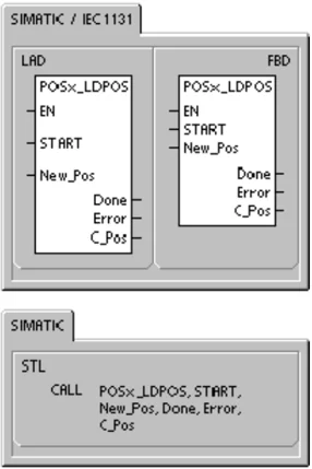
The New_Pos parameter provides the new value to replace the current position value that the Position module reports and uses for absolute moves. Based of the units of measurement, the value is either a number of pulses (DINT) or the engineering units (REAL).
The Done parameter turns on when the module completes this instruction.
The Error parameter contains the result of this instruction. See Table 9-20 for definitions of the error codes.
The C_Pos parameter contains the current position of the module. Based of the units of measurement, the value is either a number of pulses (DINT) or the number of engineering units (REAL).
Table 9-15 Parameters for the POSx_LDPOS Instruction
POSx_SRATE Instruction
The POSx_SRATE instruction (Set Rate) commands the Position module to change the acceleration, deceleration, and jerk times.
Turning on the EN bit enables the instruction. Ensure that the EN bit stays on until the Done bit signals that the execution of the instruction has completed.
Turning on the START parameter copies the new time values to the configuration/profile table and sends a SRATE command to the Position module. For each scan when the START parameter is on and the Position module is not currently busy, the instruction sends a SRATE command to the Position module. To ensure that only one command is sent, use an edge detection element to pulse the START parameter on.
The ACCEL_Time, DECEL_Time, and JERK_Time parameters determine the new acceleration time, deceleration time, and jerk time in milliseconds (ms).
The Done parameter turns on when the module completes this instruction.
The Error parameter contains the result of this instruction. See Table 9-20 for definitions of the error codes.
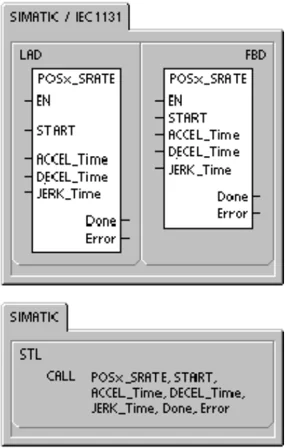
Table 9-16 Parameters for the POSx_SRATE Instruction \begin{tabular}{|l|l|l|} \hline Inputs/Outputs & Data Type & Operands \ \hline START & BOOL & I, Q, V, M, SM, S, T, C, L \ \hline ACCEL_Time, DECEL_Time, JERK_Time & DINT & ID, QD, VD, MD, SMD, SD, LD, AC, *VD, *AC, *LD, Constant \ \hline Done & BOOL & I, Q, V, M, SM, S, T, C, L \ \hline Error & BYTE & IB, QB, VB, MB, SMB, SB, LB, AC, *VD, *AC, *LD \ \hline \end{tabular}
S7-200 Programmable Controller System Manual
POSx_DIS Instruction
The POSx_DIS instruction turns the DIS output of the Position module on or off. This allows you to use the DIS output for disabling or enabling a motor controller. If you use the DIS output on the Position module, then this instruction can be called every scan or only when you need to change the value of the DIS output.
When the EN bit turns on to enable the instruction, the DIS_ON parameter controls the DIS output of the Position module. For more information about the DIS output, see Table 9-8 or refer to the specifications for the Position module in Appendix A.
The Error parameter contains the result of this instruction. See Table 9-20 for definitions of the error codes.
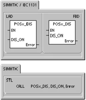
Table 9-17 Parameters for the POSx_DIS Instruction \begin{tabular}{|l|l|l|} \hline Inputs/Outputs & Data Type & Operands \ \hline DIS_ON & BYTE & IB, QB, VB, MB, SMB, SB, LB, AC, *VD, *AC, *LD, Constant \ \hline Error & BYTE & IB, QB, VB, MB, SMB, SB, LB, AC, *VD, *AC, *LD \ \hline \end{tabular}
282
POSx_CLR Instruction
The POSx_CLR instruction (Pulse the CLR Output) commands the Position module to generate a 50-ms pulse on the CLR output.
Turning on the EN bit enables the instruction. Ensure that the EN bit stays on until the Done bit signals that the execution of the instruction has completed.
Turning on the START parameter sends a CLR command to the Position module. For each scan when the START parameter is on and the Position module is not currently busy, the instruction sends a CLR command to the Position module. To ensure that only one command is sent, use an edge detection element to pulse the START parameter on.
The Done parameter turns on when the module completes this instruction.
The Error parameter contains the result of this instruction. See Table 9-20 for definitions of the error codes.
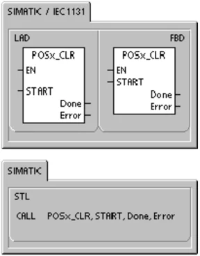
Table 9-18 Parameters for the POSx_CLR Instruction \begin{tabular}{|l|l|l|} \hline Inputs/Outputs & Data Type & Operands \ \hline START & BOOL & I, Q, V, M, SM, S, T, C, L, Power Flow \ \hline Done & BOOL & I, Q, V, M, SM, S, T, C, L \ \hline Error & BYTE & IB, QB, VB, MB, SMB, SB, LB, AC, *VD, *AC, *LD \ \hline \end{tabular}
POSx_CFG Instruction
The POSx_CFG instruction (Reload Configuration) commands the Position module to read the configuration block from the location specified by the configuration/profile table pointer. The Position module then compares the new configuration with the existing configuration and performs any required setup changes or recalculations.
Turning on the EN bit enables the instruction. Ensure that the EN bit stays on until the Done bit signals that the execution of the instruction has completed.
Turning on the START parameter sends a CFG command to the Position module. For each scan when the START parameter is on and the Position module is not currently busy, the instruction sends a CFG command to the Position module. To ensure that only one command is sent, use an edge detection element to pulse the START parameter on.
The Done parameter turns on when the module completes this instruction.
The Error parameter contains the result of this instruction. See Table 9-20 for definitions of the error codes.
Table 9-19 Parameters for the POSx_CFG Instruction
 \begin{tabular}{|l|l|l|}
\hline
Inputs/Outputs & Data Type & Operands \
\hline
START & BOOL & I, Q, V, M, SM, S, T, C, L, Power Flow \
\hline
Done & BOOL & I, Q, V, M, SM, S, T, C, L \
\hline
Error & BYTE & IB, QB, VB, MB, SMB, SB, LB, AC, *VD, *AC, *LD \
\hline
\end{tabular}