Prerequisites
The loop that you want to auto-tune must be in automatic mode. The loop output must be controlled by the execution of the PID instruction. Auto-tune will fail if the loop is in manual mode.
Before initiating an auto-tune operation your process must be brought to a stable state which means that the PV has reached setpoint (or for a P type loop, a constant difference between PV and setpoint) and the output is not changing erratically.
Ideally, the loop output value needs to be near the center of the control range when auto-tuning is started. The auto-tune procedure sets up an oscillation in the process by making small step changes in the loop output. If the loop output is close to either extreme of its control range, the step changes introduced in the auto-tune procedure may cause the output value to attempt to exceed the minimum or the maximum range limit.
If this were to happen, it may result in the generation of an auto-tune error condition, and it will certainly result in the determination of less than near optimal suggested values.
Auto-Hysteresis and Auto-Deviation
The hysteresis parameter specifies the excursion (plus or minus) from setpoint that the PV (process variable) is allowed to make without causing the relay controller to change the output. This value is used to minimize the effect of noise in the PV signal to more accurately determine the natural oscillation frequency of the process.
If you select to automatically determine the hysteresis value, the PID Auto-Tuner will enter a hysteresis determination sequence. This sequence involves sampling the process variable for a period of time and then performing a standard deviation calculation on the sample results.
In order to have a statistically meaningful sample, a set of at least 100 samples must be acquired. For a loop with a sample time of 200 msec, acquiring 100 samples takes 20 seconds. For loops with a longer sample time it will take longer. Even though 100 samples can be acquired in less than 20 seconds for loops with sample times less than 200 msec, the hysteresis determination sequence always acquires samples for at least 20 seconds.
Once all the samples have been acquired, the standard deviation for the sample set is calculated. The hysteresis value is defined to be two times the standard deviation. The calculated hysteresis value is written into the actual hysteresis field (AHYS) of the loop table.
Tip While the auto-hysteresis sequence is in progress, the normal PID calculation is not performed. Therefore, it is imperative that the process be in a stable state prior to initiating an auto-tune sequence. This will yield a better result for the hysteresis value and it will ensure that the process does not go out of control during the auto-hysteresis determination sequence.
The deviation parameter specifies the desired peak-to-peak swing of the PV around the setpoint. If you select to automatically determine this value, the desired deviation of the PV is computed by multiplying the hysteresis value by 4.5. The output will be driven proportionally to induce this magnitude of oscillation in the process during auto-tuning.
Auto-Tune Sequence
The auto-tuning sequence begins after the hysteresis and deviation values have been determined. The tuning process begins when the initial output step is applied to the loop output.
This change in output value should cause a corresponding change in the value of the process variable. When the output change drives the PV away from setpoint far enough to exceed the hysteresis boundary a zero-crossing event is detected by the auto-tuner. Upon each zero crossing event the auto-tuner drives the output in the opposite direction.
The tuner continues to sample the PV and waits for the next zero crossing event. A total of twelve zero-crossings are required to complete the sequence. The magnitude of the observed peak-to-peak PV values (peak error) and the rate at which zero-crossings occur are directly related to the dynamics of the process.
Early in the auto-tuning process, the output step value is proportionally adjusted once to induce subsequent peak-to-peak swings of the PV to more closely match the desired deviation amount. Once the adjustment is made, the new output step amount is written into the Actual Step Size field (ASTEP) of the loop table.
The auto-tuning sequence will be terminated with an error, if the time between zero crossings exceeds the zero crossing watchdog interval time. The default value for the zero crossing watchdog interval time is two hours.
Figure 15-1 shows the output and process variable behaviors during an auto-tuning sequence on a direct acting loop. The PID Tuning Control Panel was used to initiate and monitor the tuning sequence.
Notice how the auto-tuner switches the output to cause the process (as evidenced by the PV value) to undergo small oscillations. The frequency and the amplitude of the PV oscillations are indicative of the process gain and natural frequency.
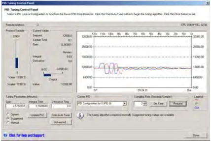
Figure 15-1 Auto-Tuning Sequence on a Direct Acting Loop
Based upon the information collected about the frequency and gain of the process during the auto-tune process, the ultimate gain and ultimate frequency values are calculated. From these values the suggested values for gain (loop gain), reset (integral time) and rate (derivative time) are calculated.
Tip Your loop type determines which tuning values are calculated by the auto-tuner. For example, for a PI loop, the auto-tuner will calculate gain and integral time values, but the suggested derivative time will be 0.0 (no derivative action).
Once the auto-tune sequence has completed, the output of the loop is returned to its initial value. The next time the loop is executed, the normal PID calculation will be performed.
PID Auto-Tune and the PID Tuning Control Panel Chapter 15
Exception Conditions
Three warning conditions can be generated during tuning execution. These warnings are reported in three bits of the ASTAT field of the loop table and, once set, these bits remain set until the next auto-tune sequence is initiated.
Warning 0 is generated if the deviation value is not at least 4X greater than the hysteresis value. This check is performed when the hysteresis value is actually known, which depends upon the auto-hysteresis setting.
Warning 1 is generated if there is more than an 8X difference between the two peak error values gathered during the first 2.5 cycles of the auto-tune procedure.
Warning 2 is generated if the measured average peak error is not at least 4X greater than the hysteresis value.
In addition to the warning conditions several error conditions are possible. Table 15-3 lists the error conditions along with a description of the cause of each error.
Table 15-3 Error Conditions during Tuning Execution \begin{tabular}{|l|l|} \hline Result Code (in ARES) & Condition \ \hline 01 aborted by user & EN bit cleared while tuning is in progress \ \hline 02 aborted due to a zero-crossing watchdog timeout & Half-cycle elapsed time exceeds zero-crossing watchdog interval \ \hline 03 aborted due to the process out-of-range & PV goes out-of-range: \newline \textbullet{} during the auto-hysteresis sequence, or \newline \textbullet{} twice before the fourth zero-crossing, or \newline \textbullet{} after the fourth zero crossing \ \hline 04 aborted due to hysteresis value exceeding maximum & User-specified hysteresis value, or automatically determined hysteresis value > maximum \ \hline 05 aborted due to illegal configuration value & The following range checking errors: \newline \textbullet{} Initial loop output value is < 0.0 or > 1.0 \newline \textbullet{} User-specified deviation value is <= hysteresis value, or is > maximum \newline \textbullet{} Initial output step is <= 0.0 or is > maximum \newline \textbullet{} Zero-crossing watchdog interval time is < minimum \newline \textbullet{} Sample time value in loop table is negative \ \hline 06 aborted due to a numeric error & Illegal floating point number or divide by zero encountered \ \hline 07 PID instruction was executed with no power flow (manual mode) & PID instruction executed with no power flow while auto-tuning is in progress or is requested \ \hline 08 auto-tuning allowed only for P, PI, PD, or PID loops & Loop type is not P, PI, PD, or PID \ \hline \end{tabular}
Notes Concerning PV Out-of-Range (Result Code 3)
The process variable is considered to be in-range by the auto-tuner if its value is greater than 0.0 and less than 1.0.
If the PV is detected to be out-of-range during the auto-hysteresis sequence, then the tuning is immediately aborted with a process out-of-range error result.
If the PV is detected to be out-of-range between the starting point of the tuning sequence and the fourth zero-crossing, then the output step value is cut in half and the tuning sequence is restarted from the beginning. If a second PV out-of-range event is detected after the first zero-crossing following the restart, then the tuning is aborted with a process out-of-range error result.
Any PV out-of-range event occurring after the fourth zero-crossing results in an immediate abort of the tuning and a generation of a process out-of-range error result.
S7-200 Programmable Controller System Manual
PID Tuning Control Panel
STEP 7-Micro/WIN includes a PID Tuning Control Panel that allows you to graphically monitor the behavior of your PID loops. In addition, the control panel allows you to initiate the auto-tune sequence, abort the sequence, and apply the suggested tuning values or your own tuning values.
To use the control panel, you must be communicating with an S7-200 PLC and a wizard-generated configuration for a PID loop must exist in the PLC. The PLC must be in RUN mode for the control panel to display the operation of a PID loop. Figure 15-2 shows the default screen for the control panel.
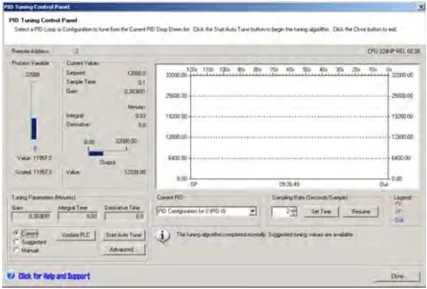
Figure 15-2 PID Tuning Control Panel
The control panel displays the station address (Remote Address) of the target PLC at the top left-hand side of the screen. At the top right-hand side of the screen, the PLC type and version number are displayed. Underneath the Remote Address field is a bar chart representation of the process variable value along with both it's scaled and unscaled values. Just to the right of the PV bar chart is a Current Values region.
In the Current Values region, the values of the Setpoint, Sample Time, Gain, Integral time, and Derivative time are displayed. The value of the Output is displayed in a horizontal bar chart along with its numerical value. To the right of the Current Values region is a graphical display.
The graphical display shows color coded plots of the PV, SP, and Output as a function of time. The PV and SP share the same vertical scale which is located at the left hand side of the graph while the vertical scale for the output is located on the right hand side of the graph.
At the bottom left hand side of the screen is the Tuning Parameters (Minutes) region. Inside this region, the Gain, Integral Time and Derivative Time values are displayed. Radio buttons indicate whether the Current, Suggested or Manual values for Gain, Integral Time and Derivative Time are being displayed. You may click on the radio button to display any one of the three sources for these values. To modify the tuning parameters, click the manual radio button.
You can use the Update PLC button to transfer the displayed Gain, Integral Time and Derivative Time values to the PLC for the PID loop that is being monitored. You can use the Start Auto Tune button to initiate an auto-tuning sequence. Once an auto-tuning sequence has started, the Start Auto Tune button becomes a Stop Auto Tune button.
Directly underneath the graphical display is a Current PID selection region with a pull down menu that allows you to select the PID loop that you wish to monitor with the control panel.
In the Sampling Rate region you can select the graphical display sampling rate from 1 to 480 seconds per sample. You can edit the sampling rate, then use the Set Time button to apply the change. The time scale of the graph is automatically adjusted to best display the data at the new rate.
You can freeze the graph by pressing the Pause button. Press the Resume button to resume sampling data at the selected rate. To clear the graph, select Clear from the right-mouse button within the graph.
388
To the right of the Chart Options region is a Legend that identifies the colors used to plot the PV, SP, and Output values.
Directly beneath the Current PID selection region is an area that is used to display information pertinent to the operation being performed.
The Advanced ... button in the Tuning Parameters region allows you to further configure parameters for the auto-tuning process. The advanced screen is shown below in Figure 15-3.
From the advanced screen you can check the box that will cause the auto-tuner to automatically determine the values for the Hysteresis and Deviation (default setting) or you can enter the values for these fields that minimize the disturbance to your process during the auto-tune procedure.
In the Other Options region you can specify the initial output step size and enter the zero crossing watchdog timeout period.
 Figure 15-3 Advanced Parameters
In the Dynamic Response Options region click the radio button that corresponds to the type of loop response that you wish to have for your process. Depending upon your process a fast response may have overshoot and would correspond to an underdamped tuning condition. A medium speed response may be on the verge of having overshoot and would correspond to a critically damped tuning condition. A slow response may not have any overshoot and would correspond to an overdamped tuning condition. A very slow response may not have overshoot and would correspond to a heavily overdamped tuning condition.
Once you have made the desired selections, click OK to return to the main screen of the PID Tuning Control Panel.
Once you have completed the auto-tune sequence and have transferred the suggested tuning parameters to the PLC, you can use the control panel to monitor your loop's response to a step change in the setpoint. Figure 15-4 shows the loop's response to a setpoint change (12000 to 14000) with the original tuning parameters (before running auto-tune).
Notice the overshoot and the long, damped ringing behavior of the process using the original tuning parameters.
 Figure 15-4 Response to a Setpoint Change
Figure 15-5 shows the loop’s response to the same setpoint change (12000 to 14000) after applying the values determined by the auto-tune process using the selection for a fast response. Notice that for this process there is no overshoot, but there is just a little bit of ringing. If you wish to eliminate the ringing at the expense of the speed of response, you need to select a medium or a slow response and re-run the auto-tuning process.
Once you have a good starting point for the tuning parameters for your loop, you can use the control panel to tweak the parameters. Then you can monitor the loop's response to a setpoint change. In this way you can fine tune your process for an optimum response in your application.
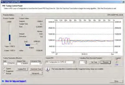
Figure 15-5 Response after Auto-Tune Process
390
Technical Specifications
In This Chapter
- General Technical Specifications ........ 392
- CPU Specifications ........ 396
- Digital Expansion Modules Specifications ........ 405
- Analog Expansion Modules Specifications ........ 412
- Thermocouple and RTD Expansion Modules Specifications ........ 424
- EM 277 PROFIBUS-DP Module Specifications ........ 438
- EM 241 Modem Module Specifications ........ 450
- EM 253 Position Module Specifications ........ 452
- (CP 243-1) Ethernet Module Specifications ........ 458
- (CP 243-1 IT) Internet Module Specifications ........ 460
- (CP 243-2) AS-Interface Module Specifications ........ 463
- Optional Cartridges ........ 465
- I/O Expansion Cable ........ 466
- RS-232/PPI Multi-Master Cable and USB/PPI Multi-Master Cable ........ 467
- Input Simulators ........ 471

General Technical Specifications
Standards Compliance
The national and international standards listed below were used to determine appropriate performance specifications and testing for the S7-200 family of products. Table A-1 defines the specific adherence to these standards.
-
European Community (CE) Low Voltage Directive 73/23/EEC
EN 61131-2:2003 Programmable controllers - Equipment requirements -
European Community (CE) EMC Directive 89/336/EEC
Electromagnetic emission standard
EN 61000-6-3:2001 residential, commercial, and light industry
EN 61000-6-4:2001 industrial environment
Electromagnetic immunity standards
EN 61000-6-2:2001 industrial environment -
European Community ATEX Directive 94/9/EC
EN 60079-15 Type of protection ‘n’
ATEX Directive applies to CPUs and expansion modules with a rated voltage of 24 VDC. It does not apply to modules with AC power systems or Relay outputs.
After July 2009, the following applies:
-
EC Directive 2006/95/EC (Low Voltage Directive) “Electrical Equipment Designed for Use within Certain Voltage Limits”
EN 61131-2:2007 Programmable controllers - Equipment requirements and tests -
EC Directive 2004/108/EC (EMC Directive) “Electromagnetic Compatibility”
EN 61000-6-4:2007: Industrial Environment
EN 61131-2:2007: Programmable controllers - Equipment requirements and tests -
EC Directive 94/9/EC (ATEX) “Equipment and Protective Systems Intending for Use in Potential Explosive Atmospheres”
EN 60079-15:2005 Type of protection ‘n’
The CE Declaration of Conformity is held on file available to competent authorities at:
Siemens AG
IA AS RD ST PLC Amberg
Werner-von-Siemens-Str. 50
D92224 Amberg
Germany
-
Underwriters Laboratories, Inc.: UL 508 Listed (Industrial Control Equipment), Registration number E75310
-
Canadian Standards Association: CSA C22.2 Number 142 (Process Control Equipment)
-
Factory Mutual Research: Class Number 3600, Class Number 3611, FM Class I, Division 2, Groups A, B, C, & D Hazardous Locations, T4A and Class I, Zone 2, IIC, T4.
Tip
The SIMATIC S7-200 series meets the CSA standard.
The cULus logo indicates that the S7-200 has been examined and certified by Underwriters Laboratories (UL) to standards UL 508 and CSA 22.2 No. 142.
Technical Specifications Appendix A
Maritime Approvals
The S7-200 products are periodically submitted for special agency approvals related to specific markets and applications. This table identifies the agency and certificate number that the S7-200 products have been approved for. Most S7-200 products in this manual have been approved for these special agency approvals. Consult your local Siemens representative if you need additional information related to the latest listing of exact approvals by part number.
\begin{tabular}{|l|l|} \hline Agency & Certificate Number \ \hline Lloyds Register of Shipping (LRS) & 99 / 20018(E1) \ \hline American Bureau of Shipping (ABS) & 01-HG20020-PDA \ \hline Germanischer Lloyd (GL) & 12 045 - 98 HH \ \hline Det Norske Veritas (DNV) & A-8862 \ \hline Bureau Veritas (BV) & 09051 / B0BV \ \hline Nippon Kaiji Kyokai (NK) & A-534 \ \hline Polski Rejestr & TE/1246/883241/99 \ \hline \end{tabular}
Relay Electrical Service Life
The typical performance data supplied by relay vendors is shown in Figure A-1. Actual performance may vary depending upon your specific application. An external protection circuit that is adapted to the load will enhance the service life of the contacts.
2A Rating
10A Rating
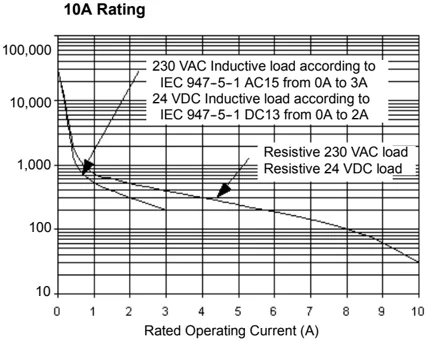
Figure A-1 Relay Electrical Service Life
Technical Specifications
All S7-200 CPUs and expansion modules conform to the technical specifications listed in Table A-1.
Notice When a mechanical contact turns on output power to the S7-200 CPU, or any digital expansion module, it sends a "1" signal to the digital outputs for approximately 50 microseconds. You must plan for this, especially if you are using devices which respond to short duration pulses.
393
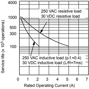
Table A-1 Technical Specifications
| Environmental Conditions — Transport and Storage | |
|---|---|
| EN 60068-2-2, Test Bb, Dry heat and EN 60068-2-1, Test Ab, Cold | -40° C to +70° C |
| EN 60068-2-30, Test Db, Damp heat | 25° C to 55° C, 95% humidity |
| EN 60068-2-14, Test Na, Temperature Shock | -40° C to +70° C dwell time 3 hours, 2 cycles |
| EN 60068-2-32, Free fall | 0.3 m, 5 times, product packaging |
| Environmental Conditions — Operating | |
|---|---|
| Ambient Temperature Range (Inlet Air 25 mm below unit) | 0° C to 55° C horizontal mounting, 0° C to 45° C vertical mounting 95% non-condensing humidity |
| Atmospheric pressure | 1080 to 795 hPa (Corresponding to an altitude of -1000 to 2000 m) |
| Concentration of contaminants | S0₂: < 0.5 ppm; H₂S: < 0.1 ppm; RH < 60% non-condensing |
| EN 60068-2-14, Test Nb, Temperature change | 5° C to 55° C, 3° C/minute |
| EN 60068-2-27 Mechanical shock | 15 G, 11 ms pulse, 6 shocks in each of 3 axis |
| EN 60068-2-6 Sinusoidal vibration | Panel mount: 7.0 mm from 5 to 9 Hz; 2 G from 9 to 150 Hz DIN rail mount: 3.5 mm from 5 to 9 Hz; 1 G from 9 to 150 Hz 10 sweeps each axis, 1 octave/minute |
| EN 60529, IP20 Mechanical protection | Protects against finger contact with high voltage as tested by standard probes. External protection is required for dust, dirt, water, and foreign objects of < 12.5 mm in diameter. |
| Electromagnetic Compatibility — Immunity per EN61000-6-2¹ | |
|---|---|
| EN 61000-4-2 Electrostatic discharge | 8 kV air discharge to all surfaces and communications port, 4 kV contact discharge to exposed conductive surfaces |
| EN 61000-4-3 Radiated electromagnetic field | 10 V/m from 80-1000 MHz, 80% AM at 1kHz 3 V/m from 1.4-2.0 GHz, 80% AM at 1kHz³ 1 V/m from 2.0-2.7 GHz, 80% AM at 1kHz³ |
| EN 61000-4-4 Fast transient bursts | 2 kV, 5 kHz with coupling network to AC and DC system power 2 kV, 5 kHz with coupling clamp to I/O 1 kV, 5 kHz with coupling clamp to communications |
| EN 61000-4-5 Surge immunity | Power supply: 2 kV asymmetrical, 1 kV symmetrical I/O 1 kV symmetrical (24 VDC circuits require external surge protection) |
| EN 61000-4-6 Conducted disturbances | 0.15 to 80 MHz, 10 V RMS, 80% AM at 1kHz |
| EN 61000-4-11 Voltage dips, short interruptions and voltage variations | Residual voltage: 0% for 1 cycle, 40% for 12 cycles and 70% for 30 cycles @ 60Hz voltage jump at zero crossing |
| VDE 0160 Non-periodic overvoltage | At 85 VAC line, 90° phase angle, apply 390 V peak, 1.3 ms pulse At 180 VAC line, 90° phase angle, apply 750 V peak, 1.3 ms pulse |
394
Technical Specifications Appendix A
Table A-1 Technical S pecifications, continued
| Electromagnetic Compatibility — Conducted and Radiated Emissions per EN 61000-6-3² and EN 61000-6-4 | |
|---|---|
| EN 55011, Class A, Group 1, conducted¹0.15 MHz to 0.5 MHz0.5 MHz to 5 MHz5 MHz to 30 MHz | < 79 dB (μV) Quasi-peak; < 66 dB (μV) Average< 73 dB (μV) Quasi-peak; < 60 dB (μV) Average< 73 dB (μV) Quasi-peak; < 60 dB (μV) Average |
| EN 55011, Class A, Group 1, radiated¹30 MHz to 230 MHz230 MHz to 1 GHz | 40 dB (μV/m) Quasi-peak; measured at 10 m47 dB (μV/m) Quasi-peak; measured at 10 m |
| EN 55011, Class B, Group 1, conducted²0.15 to 0.5 MHz0.5 MHz to 5 MHz5 MHz to 30 MHz | < 66 dB (μV) Quasi-peak decreasing with log frequency to 56 dB (μV);< 56 dB (μV) Average decreasing with log frequency to 46 dB (μV)< 56 dB (μV) Quasi-peak; < 46 dB (μV) Average< 60 dB (μV) Quasi-peak; < 50 dB (μV) Average |
| EN 55011, Class B, Group 1, radiated²30 MHz to 230 kHz230 MHz to 1 GHz | 30 dB (μV/m) Quasi-peak; measured at 10 m37 dB (μV/m) Quasi-peak; measured at 10 m |
| High Potential Isolation Test | |
| 24 V/5 V nominal circuits115/230 V circuits to ground115/230 V circuits to 115/230 V circuits115/230 V circuits to 24 V/5 V circuits | 500 VAC (type test of optical isolation boundaries)1500 VAC routine test / 2500 VDC type test1500 VAC routine test / 2500 VDC type test1500 VAC routine test / 4242 VDC type test |
1 Unit must be mounted on a grounded metallic frame with the S 7-200 ground connection made directly to the mounting metal. Cables are routed along metallic supports. 2 Unit must be mounted in a grounded metal enclosure. AC input power line must be equipped with a E P C O S B84115-E-A30 filter or equivalent, 25 cm max. wire length from filters to the S 7-200. The 24 VDC supply and sensor supply wiring must be shielded. 3 Requirements apply after J uly 2009
395
CPU Specifications
Table A-2 CPU Order Numbers
| Order Number | CPU Model | Power Supply (Nominal) | Digital Inputs | Digital Outputs | Comm Ports | Analog Inputs | Analog Outputs | Removable Connector |
|---|---|---|---|---|---|---|---|---|
| 6ES7 211-0AA23-0XB0 | CPU 221 | 24 VDC | 6 x 24 VDC | 4 x 24 VDC | 1 | No | No | No |
| 6ES7 211-0BA23-0XB0 | CPU 221 | 120 to 240 VAC | 6 x 24 VDC | 4 x Relay | 1 | No | No | No |
| 6ES7 212-1AB23-0XB0 | CPU 222 | 24 VDC | 8 x 24 VDC | 6 x 24 VDC | 1 | No | No | No |
| 6ES7 212-1BB23-0XB0 | CPU 222 | 120 to 240 VAC | 8 x 24 VDC | 6 x Relay | 1 | No | No | No |
| 6ES7 214-1AD23-0XB0 | CPU 224 | 24 VDC | 14 x 24 VDC | 10 x 24 VDC | 1 | No | No | Yes |
| 6ES7 214-1BD23-0XB0 | CPU 224 | 120 to 240 VAC | 14 x 24 VDC | 10 x Relay | 1 | No | No | Yes |
| 6ES7 214-2AD23-0XB0 | CPU 224XP | 24 VDC | 14 x 24 VDC | 10 x 24 VDC | 2 | 2 | 1 | Yes |
| 6ES7 214-2AS23-0XB0 | CPU 224XPsi | 24 VDC | 14 x 24 VDC | 10 x 24 VDC | 2 | 2 | 1 | Yes |
| 6ES7 214-2BD23-0XB0 | CPU 224XP | 120 to 240 VAC | 14 x 24 VDC | 10 x Relay | 2 | 2 | 1 | Yes |
| 6ES7 216-2AD23-0XB0 | CPU 226 | 24 VDC | 24 x 24 VDC | 16 x 24 VDC | 2 | No | No | Yes |
| 6ES7 216-2BD23-0XB0 | CPU 226 | 120 to 240 VAC | 24 x 24 VDC | 16 x Relay | 2 | No | No | Yes |
Table A-3 CPU General Specifications
| Order Number | Module Name and Description | Dimensions (mm) (W x H x D) | Weight | Dissipation | VDC Available +5 VDC | +24 VDC¹ |
|---|---|---|---|---|---|---|
| 6ES7 211-0AA23-0XB0 | CPU 221 DC/DC/DC 6 Inputs/4 Outputs | 90 x 80 x 62 | 270 g | 3 W | 0 mA | 180 mA |
| 6ES7 211-0BA23-0XB0 | CPU 221 AC/DC/Relay 6 Inputs/4 Relays | 90 x 80 x 62 | 310 g | 6 W | 0 mA | 180 mA |
| 6ES7 212-1AB23-0XB0 | CPU 222 DC/DC/DC 8 Inputs/6 Outputs | 90 x 80 x 62 | 270 g | 5 W | 340 mA | 180 mA |
| 6ES7 212-1BB23-0XB0 | CPU 222 AC/DC/Relay 8 Inputs/6 Relays | 90 x 80 x 62 | 310 g | 7 W | 340 mA | 180 mA |
| 6ES7 214-1AD23-0XB0 | CPU 224 DC/DC/DC 14 Inputs/10 Outputs | 120.5 x 80 x 62 | 360 g | 7 W | 660 mA | 280 mA |
| 6ES7 214-1BD23-0XB0 | CPU 224 AC/DC/Relay14 Inputs/10 Relays | 120.5 x 80 x 62 | 410 g | 10 W | 660 mA | 280 mA |
| 6ES7 214-2AD23-0XB0 | CPU 224XP DC/DC/DC 14 Inputs/10 Outputs | 140 x 80 x 62 | 390 g | 8 W | 660 mA | 280 mA |
| 6ES7 214-2AS23-0XB0 | CPU 224XPsi DC/DC/DC 14 Inputs/10 Outputs | 140 x 80 x 62 | 390 g | 8 W | 660 mA | 280 mA |
| 6ES7 214-2BD23-0XB0 | CPU 224XP AC/DC/Relay 14 Inputs/10 Relays | 140 x 80 x 62 | 440 g | 11 W | 660 mA | 280 mA |
| 6ES7 216-2AD23-0XB0 | CPU 226 DC/DC/DC 24 Inputs/16 Outputs | 196 x 80 x 62 | 550 g | 11 W | 1000 mA | 400 mA |
| 6ES7 216-2BD23-0XB0 | CPU 226 AC/DC/Relay 24 Inputs/16 Relays | 196 x 80 x 62 | 660 g | 17 W | 1000 mA | 400 mA |
¹ This is the 24 VDC sensor power that is available after the internal relay coil power and 24 VDC comm port power requirements have been accounted for.
396
Technical Specifications Appendix A
Table A-4 CPU S specifications
| CPU 221 | CPU 222 | CPU 224 | CPU 224XP CPU 224XPsi | CPU 226 | |
|---|---|---|---|---|---|
| Memory | |||||
| User program size with run mode edit without run mode edit | 4096 bytes 4096 bytes | 8192 bytes 12288 bytes | 12288 bytes 16384 bytes | 16384 bytes 24576 bytes | |
| User data | 2048 bytes | 8192 bytes | 10240 bytes | 10240 bytes | |
| Backup (super cap) (optional battery) | 50 hours typical (8 hours min. at □□°C) 200 days typical | 100 hours typical (70 hours min. at 40°C) 200 days typical | 100 hours typical (70 hours min. at 40°C) 200 days typical | 100 hours typical (70 hours min. at 40°C) 200 days typical | |
| I/O | |||||
| Digital I/O | 6 inputs/4 outputs | 8 inputs/6 outputs | 14 inputs/10 outputs | 14 inputs/10 outputs | 24 inputs/16 outputs |
| Analog I/O | none | 2 inputs/1 output | none | ||
| Digital I/O image size | 256 (128 In/128 Out) | ||||
| Analog I/O image size | None | 32 (16 In/16 Out) | 64 (32 In/32 Out) | ||
| Max. expansion modules allowed | None | 2 modules¹ | 7 modules¹ | ||
| Max. intelligent modules allowed | None | 2 modules¹ | 7 modules¹ | ||
| Pulse Catch inputs | 6 | 8 | 14 | 24 | |
| High-Speed Counters Single phase Two phase | 4 counters total 4 at 30 kHz 2 at 20 kHz | 6 counters total 6 at 30 kHz 4 at 20 kHz | 6 counters total 4 at 30 kHz 2 at 200 kHz 3 at 20 kHz 1 at 100 kHz | 6 counters total 6 at 30 kHz 4 at 20 kHz | |
| Pulse outputs | 2 at 20 kHz (DC outputs only) | 2 at 100 kHz (DC outputs only) | 2 at 20 kHz (DC outputs only) | ||
| General | |||||
| Timers | 256 total timers; 4 timers (1 ms); 16 timers (10 ms); 236 timers (100 ms) | ||||
| Counters | 256 (backed by super capacitor or battery) | ||||
| Internal memory bits Stored on power down | 256 (backed by super capacitor or battery) 112 (stored to EEPROM) | ||||
| Timed interrupts | 2 with 1 ms resolution | ||||
| Edge interrupts | 4 up and/or 4 down | ||||
| Analog adjustment | 1 with 8 bit resolution | 2 with 8 bit resolution | |||
| Boolean execution speed | 0.22 µs per instruction | ||||
| Real Time Clock | Optional cartridge | Built-in | |||
| Cartridge options | Memory, Battery, and Real Time Clock | Memory and battery | |||
| Communications Built-in | |||||
| Ports (Limited Power) | 1 RS-485 port | 2 RS-485 ports | |||
| PPI, MPI (slave) baud rates | 9.6, 19.2, 187.5 kbaud | ||||
| Freeport baud rates | 1.2 kbaud to 115.2 kbaud | ||||
| Max. cable length per segment | With isolated repeater: 1000 m up to 187.5 kbaud, 1200 m up to 38.4 kbaud Without isolated repeater: 50 m | ||||
| Max. number of stations | 32 per segment, 126 per network | ||||
| Max. number of masters | 32 | ||||
| Peer to Peer (PPI Master Mode) | Yes (NETR/NETW) | ||||
| MPI connections | 4 total, 2 reserved (1 for a PG and 1 for an OP) |
¹ You must calculate your power budget to determine how much power (or current) the S 7-200 CPU can provide for your configuration. If the CPU power budget is exceeded, you may not be able to connect the maximum number of modules. See Appendix A for CPU and expansion module power requirements, and Appendix B to calculate your power budget.
397
Table A-5 CPU Power Specifications
| DC | AC | |||
|---|---|---|---|---|
| Input Power | ||||
| Input voltage | 20.4 to 28.8 VDC | 85 to 264 VAC (47 to 63 Hz) | ||
| Input current | CPU only at 24 VDC | Max. load at 24 VDC | CPU only | Max. load |
| CPU 221 | 80 mA | 450 mA | 30/15 mA at □□□/□□□ VAC | 120/60 mA at 120/240 VAC |
| CPU 222 | 85 mA | 500 mA | 40/20 mA at 120/240 VAC | 140/70 mA at 120/240 VAC |
| CPU 224 | 110 mA | 700 mA | 60/30 mA at 120/240 VAC | 200/100 mA at 120/240VAC |
| CPU 224XP | 120 mA | 900 mA | 70/35 mA at 120/240 VAC | 220/100 mA at 120/240 VAC |
| CPU 224XPsi | 120 mA | 900 mA | - | - |
| CPU 226 | 150 mA | 1050 mA | 80/40 mA at 120/240 VAC | 320/160 mA at 120/240VAC |
| Inrush current | 12 A at 28.8 VDC | 20 A at 264 VAC | ||
| Isolation (field to logic) | Not isolated | 1500 VAC | ||
| Hold up time (loss of power) | 10 ms at 24 VDC | 20/80 ms at 120/240 VAC | ||
| Fuse (non-replaceable) | 3 A, 250 V Slow Blow | 2 A, 250 V Slow Blow | ||
| 24 VDC Sensor Power | ||||
| Sensor voltage (Limited Power) | L+ minus 5 V | 20.4 to 28.8 VDC | ||
| Current limit | 1.5 A peak, thermal limit non-destructive (See Table A-3 for rated load.) | |||
| Ripple noise | Derived from input power | Less than 1 V peak-to-peak | ||
| Isolation (sensor to logic) | Not isolated |
Table A-6 CPU Digital Input Specifications
| General | 24 VDC Input (CPU 221, CPU 222, CPU 224, CPU 226) | 24 VDC Input (CPU 224XP, CPU 224XPsi) | |
|---|---|---|---|
| Type | Sink/Source (IEC Type 1 Sink) | Sink/Source (IEC Type 1 Sink, except I0.3 to I0.5) | |
| Rated voltage | 24 VDC at 4 mA typical | 24 VDC at 4 mA typical | |
| Max. continuous permissible voltage | 30 VDC | ||
| Surge voltage | 35 VDC for 0.5 s | ||
| Logic 1 (min.) | 15 VDC at 2.5 mA | 15 VDC at 2.5 mA (I0.0 to I0.2 and I0.6 to I1.5) | |
| 4 VDC at 8 mA (I0.3 to I0.5) | |||
| Logic 0 (max.) | 5 VDC at 1 mA | 5 VDC at 1 mA (I0.0 to I0.2 and I0.6 to I1.5) | |
| 1 VDC at 1 mA (I0.3 to I0.5) | |||
| Input delay | Selectable (0.2 to 12.8 ms) | ||
| Connection of 2 wire proximity sensor (Bero) | |||
| Permissible leakage current (max.) | 1 mA | ||
| Isolation (field to logic) | Yes | ||
| Optical (galvanic) | 500 VAC for 1 minute | ||
| Isolation groups | See wiring diagram | ||
| High Speed Counter (HSC) input rate | |||
| HSC Inputs | Logic 1 Level | Single phase | Two phase |
| All HSC | 15 to 30 VDC | 20 kHz | 10 kHz |
| All HSC | 15 to 26 VDC | 30 kHz | 20 kHz |
| HC4, HC5 on CPU 224XP and CPU 224XPsi only | > 4 VDC | 200 kHz | 100 kHz |
| Inputs on simultaneously | All | All | |
| CPU 224XP AC/DC/RELAY only: | |||
| All at 55° C with DC inputs at 26 VDC max. | |||
| All at 50° C with DC inputs at 30 VDC max. | |||
| Cable length (max.) | |||
| Shielded | 500 m normal inputs, 50 m HSC inputs¹ | ||
| Unshielded | 300 m normal inputs |
¹ Shielded twisted pair is recommended for HSC inputs.
398
Technical Specifications Appendix A
Table A-7 CPU Digital Output S pecifications
| General | 24 VDC Output (CPU 221, CPU 222, CPU 224, CPU 226) | 24 VDC Output (CPU 224XP) | 24 VDC Output (CPU 224XPsi) | Relay Output |
|---|---|---|---|---|
| Type | Solid State-MOSFET (Sourcing) | Solid State-MOSFET (Sinking) | Dry contact | |
| Rated voltage | 24 VDC | 24 VDC | 24 VDC | 24 VDC or 250 VAC |
| Voltage range | 20.4 to 28.8 VDC | 5 to 28.8 VDC (Q0.0 to Q0.4) 20.4 to 28.8 VDC (Q0.5 to Q1.1) | 5 to 28.8 VDC | 5 to 30 VDC or 5 to 250 VAC |
| Surge current (max.) | 8 A for 100 ms | 5 A for 4 s @ 10% duty cycle | ||
| Logic 1 (min.) | 20 VDC at maximum current | L+ minus 0.4 V at max. current | External Voltage Rail minus 0.4V with 10K pullup to External Voltage Rail | - |
| Logic 0 (max.) | 0.1 VDC with 10 K Ω Load | 1M + 0.4V at max. load | - | |
| Rated current per point (max.) | 0.75 A | 2.0 A | ||
| Rated current per common (max.) | 6 A | 3.75 A | 7.5 A | 10 A |
| Leakage current (max.) | 10 μA | - | ||
| Lamp load (max.) | 5 W | 30 W DC; 200 W AC²,³ | ||
| Inductive clamp voltage | L+ minus 48 VDC, 1 W dissipation | 1M +48 VDC, 1 W dissipation | - | |
| On State resistance (contact) | 0.3 Ω typical (0.6 Ω max.) | 0.2 Ω (max. when new) | ||
| Isolation Optical (galvanic, field to logic) Logic to contact Resistance (logic to contact) Isolation groups | 500 VAC for 1 minute - - See wiring diagram | - 1500 VAC for 1 minute 100 M Ω See wiring diagram | ||
| Delay (max.) Off to on (μs) On to off (μs) Switching | 2μs (Q0.0, Q0.1), 15μs (all other) 10μs (Q0.0, Q0.1), 130μs (all other) - | 0.5μs (Q0.0, Q0.1), 15μs (all other) 1.5μs (Q0.0, Q0.1), 130μs (all other) - | - - 10 ms | |
| Pulse frequency (max.) | 20 kHz¹ (Q0.0 and Q0.1) | 100 kHz¹ (Q0.0 and Q0.1) | 100 kHz¹ (Q0.0 and Q0.1) | 1 Hz |
| Lifetime mechanical cycles | - | - | - | 10,000,000 (no load) |
| Lifetime contacts | - | - | - | 100,000 (rated load) |
| Outputs on simultaneously | All at 55° C (horizontal), All at 45° C (vertical) | |||
| Connecting two outputs in parallel | Yes, only outputs in same group | No | ||
| Cable length (max.) Shielded Unshielded | 500 m 150 m |
¹ Depending on your pulse receiver and cable, an additional external load resistor (at least 10% of rated current) may improve pulse signal quality and noise immunity.
² Relay lifetime with a lamp load will be reduced by 75% unless steps are taken to reduce the turn-on surge below the surge current rating of the output.
³ Lamp load wattage rating is for rated voltage. Reduce the wattage rating proportionally for voltage being switched (for example 120 VAC - 100 W).
Warning
When a mechanical contact turns on output power to the S7-200 CPU, or any digital expansion module, it sends a “1” signal to the digital outputs for approximately 50 microseconds.
This could cause unexpected machine or process operation which could result in death or serious injury to personnel, and/or damage to equipment.
You must plan for this, especially if you are using devices which respond to short duration pulses.
399
Table A-8 CPU 224XP and CPU 224XPsi Analog Input Specifications
\begin{tabular}{|l|l|} \hline General & Analog Input (CPU 224XP, CPU 224XPsi) \ \hline Number of Inputs & 2 points \ \hline Analog input type & Single-ended \ \hline Voltage range & ±10 V \ \hline Data word format, full scale range & -32,000 to +32,000 \ \hline DC Input impedance & > 100 K\Omega \ \hline Maximum input voltage & 30 VDC \ \hline Resolution & 11 bits plus 1 sign bit \ \hline LSB value & 4.88 mV \ \hline Isolation & None \ \hline Accuracy$^1$ & \ \quad Worst case 0° to 55° C & ±2.5% of full scale \ \quad Typical 25° C & ±1.0% of full scale \ \hline Repeatability & ±0.05% of full scale \ \hline Analog to digital conversion time & 125 msec \ \hline Conversion type & Sigma Delta \ \hline Step response & 250 ms max. \ \hline Noise rejection & -20 dB @ 50 Hz typical \ \hline \end{tabular}
$^1$ Analog input accuracy may deviate up to +/-10% of full scale when subjected to severe RF interferences such as specified in the product standard EN 61131-2:2007.
Table A-9 CPU 224XP and CPU 224XPsi Analog Output Specifications
\begin{tabular}{|l|l|} \hline General & Analog Output (CPU 224XP, CPU 224XPsi) \ \hline Number of outputs & 1 point \ \hline Signal range & \ \quad Voltage & 0 to 10 V (Limited Power) \ \quad Current & 0 to 20 mA (Limited Power) \ \hline Data word format, full range & 0 to +32767 \ \hline Date word format, full scale & 0 to +32000 \ \hline Resolution, full range & 12 bits \ \hline LSB value & \ \quad Voltage & 2.44 mV \ \quad Current & 4.88 \muA \ \hline Isolation & none \ \hline Accuracy & \ \quad Worst case, 0° to 55° C & \ \qquad Voltage output & ± 2% of full-scale \ \qquad Current output & ± 3% of full-scale \ \quad Typical 25° C & \ \qquad Voltage output & ± 1% of full-scale \ \qquad Current output & ± 1% of full-scale \ \hline Settling time & \ \quad Voltage output & < 50 \muS \ \quad Current output & < 100 \muS \ \hline Maximum output drive & \ \quad Voltage output & ≥ 5000 \Omega minimum \ \quad Current output & ≤ 500 \Omega maximum \ \hline \end{tabular}
400
Technical Specifications Appendix A
Wiring Diagrams
 Figure A-2 CPU Inputs and Outputs
 Figure A-3 CPU 221 Wiring Diagrams
401
 CPU 222 DC/DC/DC
(6ES7 212-1AB23-0XB0) 24 VDC Power
M L+ 0.0 0.1 0.2 0.3 0.4 0.5 • ⏚ M L+ DC 1M 0.0 0.1 0.2 0.3 2M 0.4 0.5 0.6 0.7 M L+
24 VDC Sensor Power Output
CPU 222 AC/DC/Relay (6ES7 212-1BB23-0XB0) 120/240 VAC Power
N(-) L(+) N(-) L(+)
1L 0.0 0.1 0.2 • 2L 0.3 0.4 0.5 ⏚ N L1 AC 1M 0.0 0.1 0.2 0.3 2M 0.4 0.5 0.6 0.7 M L+
24 VDC Sensor Power Output
CPU 224 DC/DC/DC (6ES7 214-1AD23-0XB0) 24 VDC Power
1M 1L+ 0.0 0.1 0.2 0.3 0.4 2M 2L+ 0.5 0.6 0.7 1.0 1.1 • ⏚ M L+ DC 1M 0.0 0.1 0.2 0.3 0.4 0.5 0.6 0.7 2M 1.0 1.1 1.2 1.3 1.4 1.5 M L+
24 VDC Sensor Power Output
CPU 224 AC/DC/Relay (6ES7 214-1BD23-0XB0) 120/240 VAC Power
N(-) L(+) N(-) L(+) N(-) L(+)
1L 0.0 0.1 0.2 0.3 • 2L 0.4 0.5 0.6 • 3L 0.7 1.0 1.1 ⏚ N L1 AC 1M 0.0 0.1 0.2 0.3 0.4 0.5 0.6 0.7 2M 1.0 1.1 1.2 1.3 1.4 1.5 M L+
24 VDC Sensor Power Output
Figure A-4 CPU 222 and CPU 224 Wiring Diagrams
402
Technical Specifications Appendix A
 CPU 224XP Analog I/O
CPU 224XP DC/DC/DC (6ES7 214-2AD23-0XB0)
24 VDC Power
M I V M A+ B+
1M 1L+ 0.0 0.1 0.2 0.3 0.4 2M 2L+ 0.5 0.6 0.7 1.0 1.1 • ⏚ M L+ DC
1M 0.0 0.1 0.2 0.3 0.4 0.5 0.6 0.7 2M 1.0 1.1 1.2 1.3 1.4 1.5 M L+
24 VDC Sensor
Power Output
CPU 224XPsi Analog I/O CPU 224XPsi DC/DC/DC (6ES7 214-2AS23-0XB0) 24 VDC Power M I V M A+ B+ 1M • 0.0 0.1 0.2 0.3 0.4 • • 0.5 0.6 0.7 1.0 1.1 • ⏚ M L+ DC 1M 0.0 0.1 0.2 0.3 0.4 0.5 0.6 0.7 2M 1.0 1.1 1.2 1.3 1.4 1.5 M L+ 24 VDC Sensor Power Output
CPU 224XP Analog I/O CPU 224XP AC/DC/Relay (6ES7 214-2BD23-0XB0) 120/240 VAC Power N(-) L(+) N(-) L(+) N(-) L(+) M I V M A+ B+ 1L 0.0 0.1 0.2 0.3 • 2L 0.4 0.5 0.6 • 3L 0.7 1.0 1.1 ⏚ N L1 AC 1M 0.0 0.1 0.2 0.3 0.4 0.5 0.6 0.7 2M 1.0 1.1 1.2 1.3 1.4 1.5 M L+ 24 VDC Sensor Power Output
Figure A-5 CPU 224XP Wiring Diagrams
403
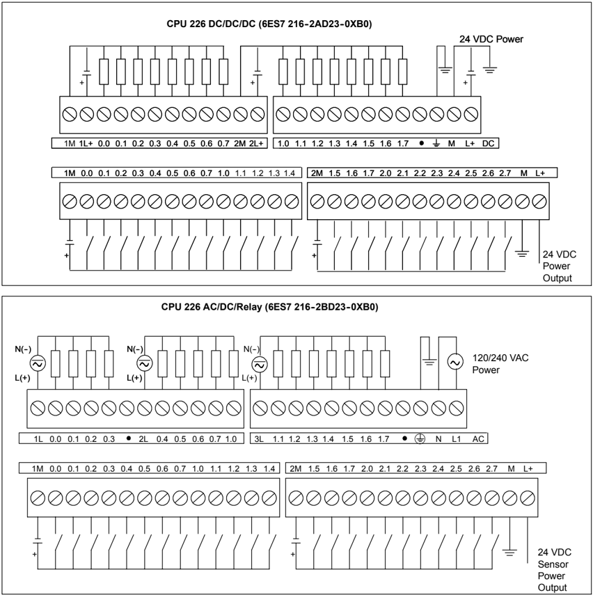
Figure A-6 CPU 226 Wiring Diagrams
Table A-10 Pin Assignments for the S7-200 Communications Port (Limited Power)
| Connector | Pin Number | PROFIBUS Signal | Port 0/Port 1 |
|---|---|---|---|
| Pin 1Pin 5 | 1 | S shield | Chassis ground |
| 2 | 24 V Return | Logic common | |
| 3 | RS-485 Signal B | RS-485 Signal B | |
| 4 | Request-to-Send | RTS (TTL) | |
| 5 | 5 V Return | Logic common | |
| 6 | +5 V | +5 V, 100 Ω series resistor | |
| 7 | +24 V | +24 V | |
| 8 | RS-485 Signal A | RS-485 Signal A | |
| 9 | Not applicable | 10-bit protocol select (input) | |
| Connector shell | S shield | Chassis ground |
404
Technical Specifications Appendix A
Digital Expansion Modules Specifications
Table A-11 Digital Expansion Modules Order Numbers
| Order Number | Expansion Model | Digital Inputs | Digital Outputs | Removable Connector |
|---|---|---|---|---|
| 6ES7 221-1BF22-0XA0 | EM 221 Digital Input 8 x 24 VDC | 8 x 24 VDC | - | Yes |
| 6ES7 221-1EF22-0XA0 | EM 221 Digital Input 8 x 120/230 VAC | 8 x 120/230 VAC | - | Yes |
| 6ES7 221-1BH22-0XA0 | EM 221 Digital Input 16 x 24 VDC | 16 x 24 VDC | - | Yes |
| 6ES7 222-1BD22-0XA0 | EM 222 Digital Output 4 x 24 VDC -5A | - | 4 x 24 VDC -5A | Yes |
| 6ES7 222-1HD22-0XA0 | EM 222 Digital Output 4 x Relays-10A | - | 4 x Relay-10A | Yes |
| 6ES7 222-1BF22-0XA0 | EM 222 Digital Output 8 x 24 VDC | - | 8 x 24 VDC -0.75A | Yes |
| 6ES7 222-1HF22-0XA0 | EM 222 Digital Output 8 x Relays | - | 8 x Relay-2A | Yes |
| 6ES7 222-1EF22-0XA0 | EM 222 Digital Output 8 x 120/230 VAC | - | 8 x 120/230 VAC | Yes |
| 6ES7 223-1BF22-0XA0 | EM 223 24 VDC Digital Comb 4 Inputs/4 Outputs | 4 x 24 VDC | 4 x 24 VDC -0.75A | Yes |
| 6ES7 223-1HF22-0XA0 | EM 223 24 VDC Digital Comb 4 Inputs/4 Relay Outputs | 4 x 24 VDC | 4 x Relay-2A | Yes |
| 6ES7 223-1BH22-0XA0 | EM 223 24 VDC Digital Comb 8 Inputs/8 Outputs | 8 x 24 VDC | 8 x 24 VDC -0.75A | Yes |
| 6ES7 223-1PH22-0XA0 | EM 223 24 VDC Digital Comb 8 Inputs/8 Relay Outputs | 8 x 24 VDC | 8 x Relay-2A | Yes |
| 6ES7 223-1BL22-0XA0 | EM 223 24 VDC Digital Comb 16 Inputs/16 Outputs | 16 x 24 VDC | 16 x 24 VDC -0.75A | Yes |
| 6ES7 223-1PL22-0XA0 | EM 223 24 VDC Digital Comb 16 Inputs/16 Relay Outputs | 16 x 24 VDC | 16 x Relay-2A | Yes |
| 6ES7 223-1BM22-0XA0 | EM 223 24 VDC Digital Comb 32 Inputs/32 Outputs | 32 x 24 VDC | 32 x 24 VDC -0.75 A | Yes |
| 6ES7 223-1PM22-0XA0 | EM 223 24 VDC Digital Comb 32 Inputs/32 Relay Outputs | 32 x 24 VDC | 32 x Relay-2 A | Yes |
Table A-12 Digital Expansion Modules General Specifications
| Order Number | Module Name and Description | Dimensions (mm) (W x H x D) | Weight | Dissipation | VDC Requirements | +5 VDC | +24 VDC |
|---|---|---|---|---|---|---|---|
| 6ES7 221-1BF22-0XA0 | EM 221 DI 8 x 24 VDC | 46 x 80 x 62 | 150 g | 2 W | 30 mA | ON: 4 mA/input | |
| 6ES7 221-1EF22-0XA0 | EM 221 DI 8 x 120/230 VAC | 71.2 x 80 x 62 | 160 g | 3 W | 30 mA | - | |
| 6ES7 221-1BH22-0XA0 | EM 221 DI 16 x 24 VDC | 71.2 x 80 x 62 | 160 g | 3 W | 70 mA | ON: 4 mA/input | |
| 6ES7 222-1BD22-0XA0 | EM 222 DO 4 x 24 VDC -5A | 46 x 80 x 62 | 120 g | 3 W | 40 mA | - | |
| 6ES7 222-1HD22-0XA0 | EM 222 DO 4 x Relays-10A | 46 x 80 x 62 | 150 g | 4 W | 30 mA | ON: 20 mA/output | |
| 6ES7 222-1BF22-0XA0 | EM 222 DO 8 x 24 VDC | 46 x 80 x 62 | 150 g | 2 W | 50 mA | - | |
| 6ES7 222-1HF22-0XA0 | EM 222 DO 8 x Relays | 46 x 80 x 62 | 170 g | 2 W | 40 mA | ON: 9 mA/output | |
| 6ES7 222-1EF22-0XA0 | EM 222 DO 8 x 120/230 VAC | 71.2 x 80 x 62 | 165 g | 4 W | 110 mA | - | |
| 6ES7 223-1BF22-0XA0 | EM 223 24 VDC 4 In/4 Out | 46 x 80 x 62 | 160 g | 2 W | 40 mA | ON: 4 mA/input | |
| 6ES7 223-1HF22-0XA0 | EM 223 24 VDC 4 In/4 Relays | 46 x 80 x 62 | 170 g | 2 W | 40 mA | ON: 9 mA/output, 4 mA/input | |
| 6ES7 223-1BH22-0AX0 | EM 223 24 VDC 8 In/8 Out | 71.2 x 80 x 62 | 200 g | 3 W | 80 mA | ON: 4 mA/input | |
| 6ES7 223-1PH22-0XA0 | EM 223 24 VDC 8 In/8 Relays | 71.2 x 80 x 62 | 300 g | 3 W | 80 mA | ON: 9 mA/output, 4 mA/input | |
| 6ES7 223-1BL22-0XA0 | EM 223 24 VDC 16 In/16 Out | 137.3 x 80 x 62 | 360 g | 6 W | 160 mA | ON: 4 mA/input | |
| 6ES7 223-1PL22-0XA0 | EM 223 24 VDC 16 In/16 Relays | 137.3 x 80 x 62 | 400 g | 6 W | 150 mA | ON: 9 mA/output, 4 mA/input | |
| 6ES7 223-1BM22-0XA0 | EM 223 24 VDC 32 In/32 Out | 196 x 80 x 62 | 500 g | 9 W | 240 mA | ON: 4 mA/input | |
| 6ES7 223-1PM22-0XA0 | EM 223 24 VDC 32 In/32 Relay | 196 x 80 x 62 | 580 g | 13 W | 205 mA | ON: 9 mA/output 4 mA/input |
405
Table A-13 Digital Expansion Modules Input Specifications
| General | 24 VDC Input | 120/230 VAC Input (47 to 63 HZ) |
|---|---|---|
| Type | Sink/Source (IEC Type 1 sink) | IEC Type I |
| Rated voltage | 24 VDC at 4 mA | 120 VAC at 6 mA or 230 VAC at 9 mA nominal |
| Maximum continuous permissible voltage | 30 VDC | 264 VAC |
| Surge voltage (max.) | 35 VDC for 0.5 s | - |
| Logic 1 (min.) | 15 VDC at 2.5 mA | 79 VAC at 2.5 mA |
| Logic 0 (max.) | 5 VDC at 1 mA | 20 VAC or 1 mA AC |
| Input delay (max.) | 4.5 ms | 15 ms |
| Connection of 2 wire proximity sensor (Bero) | ||
| Permissible leakage current (max.) | 1 mA | 1 mA AC |
| Isolation | ||
| Optical (galvanic, field to logic) | 500 VAC for 1 minute | 1500 VAC for 1 minute |
| Isolation groups | See wiring diagram | 1 point |
| Inputs on simultaneously | All at 55° C (horizontal), All on at 45° C (vertical) | |
| Cable length (max.) | ||
| Shielded | 500 m | 500 m |
| Unshielded | 300 m | 300 m |
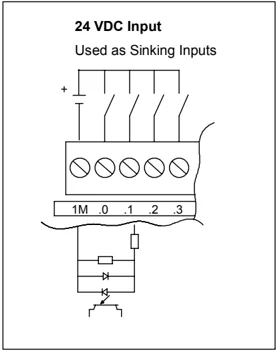
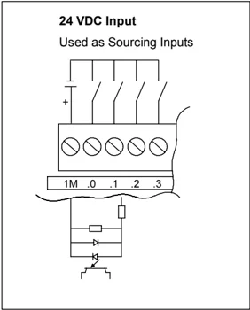
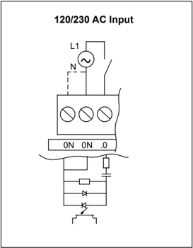
Figure A-7 S7-200 Digital Expansion Modules Inputs
406
Technical Specifications Appendix A
Table A-14 Digital Expansion Modules Output Specifications
| General | 24 VDC Output | Relay Output | 120/230 VAC Output | ||
|---|---|---|---|---|---|
| 0.75 A | 5 A | 2 A | 10 A | ||
| Type | Solid state-MOSFET (Sourcing) | Dry contact | Triac, zero-cross turn-on | ||
| Rated voltage | 24 VDC | 24 VDC or 250 VAC | 120/230 VAC | ||
| Voltage range | 20.4 to 28.8 VDC | 5 to 30 VDC or 5 to 250 VAC | 12 to 30 VDC or 12 to 250 VAC | 40 to 264 VAC (47 to 63 Hz) | |
| 24 VDC coil power voltage range | - | 20.4 to 28.8 VDC | - | ||
| Surge current (max.) | 8 A for 100 ms | 30 A | 5 A for 4 s @ 10% duty cycle | 15 A for 4 s @ 10% duty cycle | 5 A rms for 2 AC cycles |
| Logic 1 (min.) | 20 VDC | - | L1 (-0.9 V rms) | ||
| Logic 0 (max.) | 0.1 VDC with 10 K Ω Load | 0.2 VDC with 5 K Ω Load | - | - | |
| Rated current per point (max.) | 0.75 A | 5 A | 2.00 A | 10 A resistive; 2 A DC inductive; 3 A AC inductive | 0.5 A AC¹ |
| Rated current per common (max.) | 10 A | 5 A | 10 A | 10 A | 0.5 A AC |
| Leakage current (max.) | 10 μA | 30 μA | - | 1.1 mA rms at 132 VAC and 1.8 mA rms at 264 VAC | |
| Lamp load (max.) | 5 W | 50 W | 30 W DC/ 200 W AC⁴,⁵ | 100 W DC/ 1000 W AC | 60 W |
| Inductive clamp voltage | L+ minus 48 V | L+ minus 47 V² | - | - | |
| On state resistance (contact) | 0.3 Ω typical (0.6 Ω max.) | 0.05 Ω max. | 0.2 Ω max. when new | 0.1 Ω max. when new | 410 Ω max. when load current is less than 0.05A |
| Isolation | |||||
| Optical (galvanic, field to logic) | 500 VAC for 1 minute | - | 1500 VAC for 1 minute | ||
| Coil to logic | - | None | - | ||
| Coil to contact | - | 1500 VAC for 1 minute | - | ||
| Resistance (coil to contact) | - | 100 M Ω min. when new | - | ||
| Isolation groups | See wiring diagram | See wiring diagram | 1 point | ||
| Delay Off to On/On to Off (max.) | 50 μs / 200 μs | 500 μs | - | - | 0.2 ms + 1/2 AC cycle |
| Switching (max.) | - | - | 10 ms | 15 ms | - |
| Switching frequency (max.) | - | 1 Hz | 10 Hz | ||
| Lifetime mechanical cycles | - | 10,000,000 (no load) | 30,000,000 (no load) | - | |
| Lifetime contacts | - | 100,000 (rated load) | 30,000 (rated load) | - | |
| Output on simultaneously | All at 55° C (horizontal), All at 45° C (vertical) | All at 55 °C (horizontal) with 20A max. module current. All at 45°C (vertical) with 20A max. module current⁵. All at 40 °C (horizontal) with 10A per point | All at 55° C (horizontal), All at 45° C (vertical) | ||
| Connecting two outputs in parallel | Yes, only outputs in same group | No | No | ||
| Cable length (max.) | |||||
| Shielded | 500 m | 500 m | 500 m | ||
| Unshielded | 150 m | 150 m | 150 m |
1 Load current must be full wave AC and must not be half-wave because of the zero-cross circuitry. Minimum load current is 0.05 A AC. With a load current between 5 mA and 50 mA AC, the current can be controlled, but there is an additional voltage drop due to series resistance of 410 Ohms.
2 If the output overheats due to excessive inductive switching or abnormal conditions, the output point may turn off or be damaged. The output could overheat or be damaged if the output is subjected to more than 0.7 J of energy switching an inductive load off. To eliminate the need for this limitation, a suppression circuit as described in Chapter 3 can be added in parallel with the load. These components need to be sized properly for the given application.
3 The EM 222 DO 4 x Relay has a different FM rating than the rest of the S7-200. This module has a T4 rating, instead of T4A for FM Class I, Division Groups A, B, C, and D Hazardous Locations.
4 Relay lifetime with a lamp load will be reduced by 75% unless steps are taken to reduce the turn-on surge below the surge current rating of the output.
5 Lamp load wattage rating is for rated voltage. Reduce the wattage rating proportionally for voltage being switched (for example 120 VAC - 100 W).

Warning
When a mechanical contact turns on output power to the S7-200 CPU, or any digital expansion module, it sends a “1” signal to the digital outputs for approximately 50 microseconds.
This could cause unexpected machine or process operation which could result in death or serious injury to personnel, and/or damage to equipment.
You must plan for this, especially if you are using devices which respond to short duration pulses.
407
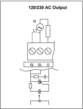
 Figure A-8 S7-200 Digital Expansion Modules Outputs
Wiring Diagrams
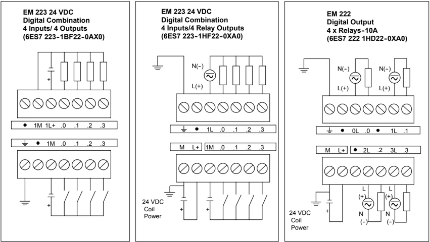
 Figure A-9 Wiring Diagrams for EM 222 and EM 223 Expansion Modules
408
Technical Specifications Appendix A
 EM 221 Digital Input 8 x 24 VDC
(6ES7 221-1BF22-0XA0)
● ● 1M .0 .1 .2 .3 ⊣ ● 2M .4 .5 .6 .7
EM 221 Digital Input 16 x 24 VDC (6ES7 221-1BH22-0XA0)
● ● 1M .0 .1 .2 .3 2M .4 .5 .6 .7 ⊣ ● 3M .0 .1 .2 .3 4M .4 .5 .6 .7
EM 221 Digital Input 8 x AC 120/230 V (6ES7 221-1EF22-0XA0)
0N 0N .0 1N 1N .1 2N 2N .2 3N 3N .3 ⊣ 4N .4 5N 5N .5 6N 6N .6 7N 7N .7
EM 222 Digital Output 8 x AC 120/230 V (6ES7 222-1EF22-0AX0)
N L1 0L 0L .0 1L 1L .1 2L 2L .2 3L 3L .3 ⊣ 4L .4 5L 5L .5 6L 6L .6 7L 7L .7
EM 222 Digital Output 8 x 24 VDC (6ES7 222-1BF22-0XA0)
● 1M 1L+ .0 .1 .2 .3 ⊣ 2M 2L+ .4 .5 .6 .7
EM 222 Digital Output 8 x Relays (6ES7 222 1HF22-0XA0)
N(-) L(+) ⊣ ● 1L .0 .1 .2 .3 M L+ 2L .4 .5 .6 .7 24 VDC Coil + power L (+) N (-)
EM 222 Digital Output 4 x 24 VDC -5A (6ES7 222-1BD22-0XA0)
● 0M 0L+ .0 1M 1L+ .1 ⊣ 2M 2L+ .2 3M 3L+ .3
Figure A-10 Wiring Diagrams for EM 221 and EM 222 Expansion Modules
409
EM 223 24 VDC Digital Combination 8 Inputs/8 Outputs (6ES7 223-1BH22-0XA0)
EM 223 24 VDC Digital Combination 8 Inputs/8 Relay Out- puts (6ES7 223-1PH22-0XA0)
EM 223 24 VDC Digital Combination 16 Inputs/16 Outputs (6ES7 223-1BL22-0XA0)
EM 223 24 VDC Digital Combination 16 Inputs/16 Relay Outputs (6ES7 223-1PL22-0XA0)
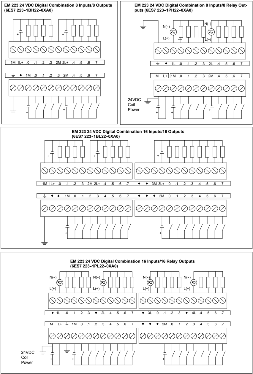
Figure A-11 Wiring Diagrams for EM 223 Expansion Modules
410