Downloading and Uploading the Elements of Your Project
Your project consists of different elements:
Program block
Data block (optional)
System block (optional)
Recipes (optional)
Data log configurations (optional)
When you download a project, the program block, data block and system block are stored in permanent memory for safekeeping. Recipes and data log configurations are stored in the memory cartridge, and replace any existing recipes and data logs. Any program elements not included in the download operation are left unchanged in permanent memory and the memory cartridge.
If a project download includes recipes or data log configurations, the memory cartridge must remain installed for proper program operation.
To download your project to an S7-200 CPU:
- Select the File > Download menu command.
- Click each project element you wish to download.
- Click the Download Button.
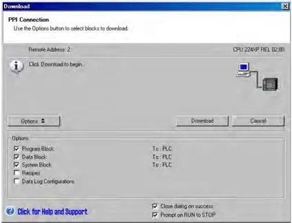
Figure 4-14 Download a Project to S7-200 CPU
When you upload a project to your computer using STEP 7-Micro/WIN, the S7-200 uploads the program block, data block and system block from permanent memory. The recipes and data log configurations are uploaded from the memory cartridge. The data from the data logs is not uploaded to your computer using STEP 7-Micro/WIN. The S7-200 Explorer is used to upload the data from the data logs (see Chapter 14).
To upload your project from an S7-200 CPU:
- Select the File > Upload menu command.
- Click each project element that you wish to upload.
- Click the Upload Button.
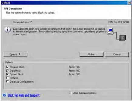
Figure 4-15 Upload a Project to the S7-200
S7-200 Programmable Controller System Manual
Storing your Program on a Memory Cartridge
The S7-200 allows you to copy your user program from one CPU to another using a memory cartridge. You can also distribute updates for any of the following blocks in your S7-200: the program block, system block or data block.
Before copying any program elements to the memory cartridge, STEP 7-Micro/WIN deletes all program elements (including recipes and data logs) except for user files on the memory cartridge. If your program will not fit because of the size of your files, you can do one of two things to create enough storage space for your program. You can either erase the memory cartridge using the PLC > Erase Memory Cartridge menu command. Or, you can open the S7-200 Explorer and remove user files that are no longer needed.
The PLC must be in STOP mode to program the memory cartridge.
To store your program in the memory cartridge:
- Select the PLC > Program Memory Cartridge menu command.
- Click each project element you wish to copy to the memory cartridge (all program elements that exist in your project are selected by default). If the system block is selected the force values will be copied as well.
- Click the Program Button
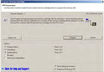
Figure 4-16 Store a Program on a Memory Cartridge
The program block, system block, data block, and any forced values are copied from permanent memory in the S7-200 to the memory cartridge. The recipes and data log configurations are copied from STEP 7-Micro/WIN to the memory cartridge.
Restoring a Program from a Memory Cartridge
To transfer the program from a memory cartridge to the S7-200, you must apply power to the S7-200 with the memory cartridge installed. If any of the blocks or force values present in the memory cartridge are different from the blocks or force values in the S7-200, then all blocks present in the memory cartridge are copied to the S7-200.
If a program block was transferred from the memory cartridge, the program block in permanent memory is replaced.
If a data block was transferred from the memory cartridge, the data block in permanent memory is replaced, all of V memory is cleared, and V memory is initialized with the contents of the data block.
If a system block was transferred from the memory cartridge, the system block and force values in the permanent memory are replaced and all retentive memory is cleared.
Once the transferred program has been stored to permanent memory you can remove the memory cartridge. However, if recipes or data logs are present in the cartridge, you must leave the memory cartridge installed. Leaving the memory cartridge installed will delay entry to RUN mode on subsequent power cycles.
Notice
Powering on an S7-200 CPU with an installed memory cartridge that was programmed by a different model of S7-200 CPU can cause an error. Memory cartridges that are programmed by a lower model number CPU can be read by a higher model number CPU. However, the opposite is not true. For example, memory cartridges that are programmed by a CPU 221 or CPU 222 can be read by a CPU 224, but memory cartridges that are programmed by a CPU 224 are rejected by a CPU 221 or CPU 222.
For a complete list of memory cartridge usage restrictions, see Optional Cartridges (Memory Cartridge) in Appendix A.
Saving the Retentive M Memory Area on Power Loss
If you configured any of the first 14 bytes of bit memory (MB0 to MB13) to be retentive, these bytes are saved to permanent memory when the S7-200 loses power. By default, the first 14 bytes of M memory are selected to be non-retentive.
Restoring Data after Power On
When power is applied, the S7-200 restores the program block and the system block from permanent memory. The S7-200 then verifies that the super capacitor and optional battery cartridge, if installed, has successfully maintained the data stored in RAM memory. If the data was successfully maintained, the retentive areas of user data memory are left unchanged. The non-retentive portions of V memory are restored from the contents of the data block in permanent memory. The non-retentive portions of other memory areas are cleared.
If the contents of RAM were not maintained (such as after an extended power failure), the S7-200 clears all user data areas, sets the Retentive Data Lost memory bit (SM0.2), restores V memory from the contents of the data block in permanent memory, and restores the first 14 bytes of M memory from permanent memory if these bytes were previously configured as retentive.
Using Your Program to Save V Memory to Permanent Memory
You can save a value (byte, word, or double word) stored in any location of the V memory area to permanent memory. A save to permanent memory operation typically increases the scan time by 10 to 15 ms. The value written by the Save operation overwrites any previous value stored in the V memory area of permanent memory.
The save to permanent memory operation does not update the data in the memory cartridge.
Tip Since the number of save operations to the permanent memory (EEPROM) is limited (100,000 minimum, and 1,000,000 typical), you should ensure that only necessary values are saved. Otherwise, the EEPROM can wear out and the CPU can fail. Typically, you should perform save operations at the occurrence of specific events that occur rather infrequently.
For example, if the scan time of the S7-200 is 50 ms and a value was saved once per scan, the EEPROM would last a minimum of 5,000 seconds, which is less than an hour and a half. On the other hand, if a value were saved once an hour, the EEPROM would last a minimum of 11 years.
Copying V Memory to Permanent Memory
Special Memory Byte 31 (SMB31) commands the S7-200 to copy a value in V memory to the V memory area of permanent memory. Special Memory Word 32 (SMW32) stores the address location of the value that is to be copied. Figure 4-17 shows the format of SMB31 and SMW32.
Use the following steps to program the S7-200 to save or write a specific value in V memory:
- Load the V memory address of the value to be saved in SMW32.
- Load the size of the data in SM31.0 and SM31.1, as shown in Figure 4-17.
- Set SM31.7 to 1.
At the end of every scan cycle, the S7-200 checks SM31.7; if SM31.7 equals 1, the specified value is saved to permanent memory. The operation is complete when the S7-200 resets SM31.7 to 0.
Do not change the value in V memory until the save operation is complete.
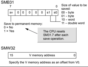
Figure 4-17 SMB31 and SMW32
Tip
Copying V Memory to permanent memory can be used to save values that are created from an HMI and stored from the program to the internal EEPROM.
To include the values saved to the internal EEPROM in your STEP 7-Micro/WIN project, you must upload the DB. However, this upload is only possible if the DB (which included a variable that was at an equal or higher address than the V Memory address saved in SMW32) was previously downloaded from STEP 7-Micro/WIN.
Sample Program: Copying V Memory to the Permanent Memory
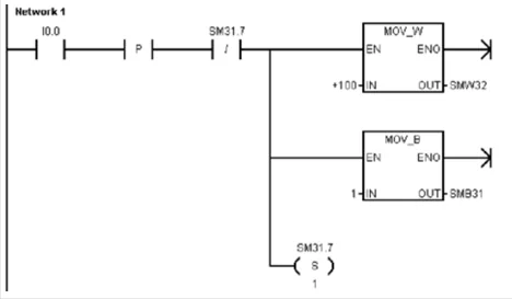
This example transfers VB100 to permanent memory. On a rising edge of I0.0, if another transfer is not in progress, it loads the address of the V memory location to be transferred to SMW32. It selects the amount of V memory to transfer (1=Byte; 2=Word; 3=Double Word or Real). It then sets SM31.7 to have the S7-200 transfer the data at the end of the scan.
The S7-200 automatically resets SM31.7 when the transfer is complete.
Selecting the Operating Mode for the S7-200 CPU
The S7-200 has two modes of operation: STOP mode and RUN mode. The status LEDs on the front of the CPU indicates the current mode of operation. In STOP mode, the S7-200 is not executing the program, and you can download a program or the CPU configuration. In RUN mode, the S7-200 is running the program.
-
The S7-200 provides a mode switch for changing the mode of operation. You can use the mode switch (located under the front access door of the S7-200) to manually select the operating mode: setting the mode switch to STOP mode stops the execution of the program; setting the mode switch to RUN mode starts the execution of the program; and setting the mode switch to TERM (terminal) mode does not change the operating mode.
If a power cycle occurs when the mode switch is set to either STOP or TERM, the S7-200 goes automatically to STOP mode when power is restored. If a power cycle occurs when the mode switch is set to RUN, the S7-200 goes to RUN mode when power is restored.
-
STEP 7-Micro/WIN allows you to change the operating mode of the online S7-200. To enable the software to change the operating mode, you must manually set the mode switch on the S7-200 to either TERM or RUN. You can use the PLC > STOP or PLC > RUN menu commands or the associated buttons on the toolbar to change the operating mode.
-
You can insert the STOP instruction in your program to change the S7-200 to STOP mode. This allows you to halt the execution of your program based on the program logic. For more information about the STOP instruction, see Chapter 6.
40
PLC Concepts Chapter 4
Using the S7-200 Explorer
The S7-200 Explorer is an extension to the Windows Explorer application that provides access to S7-200 PLCs and allows the contents of each connected PLC to be explored. The different blocks that may reside in either the PLC or the memory cartridge can be determined. Properties are available for each block.
Since the S7-200 Explorer is an extension to the Windows Explorer application, standard Windows navigation and behaviors are supported.
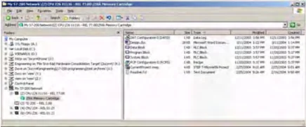
Figure 4-18 S7-200 Explorer
The S7-200 Explorer is the mechanism used to read data log data stored within the memory cartridge. Refer to Chapter 14 for more information about data logs.
The S7-200 Explorer can also be used to read or write user files to the memory cartridge. These can be any type of files, Word documents, bitmap files, jpeg files, or STEP 7-Micro/WIN projects.
Features of the S7-200
The S7-200 provides several special features that allow you to customize how the S7-200 functions to better fit your application.
The S7-200 Allows Your Program to Immediately Read or Write the I/O
The S7-200 instruction set provides instructions that immediately read from or write to the physical I/O. These immediate I/O instructions allow direct access to the actual input or output point, even though the image registers are normally used as either the source or the destination for I/O accesses.
The corresponding process-image input register location is not modified when you use an immediate instruction to access an input point. The corresponding process-image output register location is updated simultaneously when you use an immediate instruction to access an output point.
Tip The S7-200 handles reads of analog inputs as immediate data, unless you enable analog input filtering. When you write a value to an analog output, the output is updated immediately.
It is usually advantageous to use the process-image register rather than to directly access inputs or outputs during the execution of your program. There are three reasons for using the image registers:
- The sampling of all inputs at the start of the scan synchronizes and freezes the values of the inputs for the program execution phase of the scan cycle. The outputs are updated from the image register after the execution of the program is complete. This provides a stabilizing effect on the system.
- Your program can access the image register much more quickly than it can access I/O points, allowing faster execution of the program.
- I/O points are bit entities and must be accessed as bits or bytes, but you can access the image register as bits, bytes, words, or double words. Thus, the image registers provide additional flexibility.
The S7-200 Allows Your Program to Interrupt the Scan Cycle
If you use interrupts, the routines associated with each interrupt event are stored as part of the program. The interrupt routines are not executed as part of the normal scan cycle, but are executed when the interrupt event occurs (which could be at any point in the scan cycle).
Interrupts are serviced by the S7-200 on a first-come-first-served basis within their respective priority assignments. See the Interrupt instructions in Chapter 6 for more information.
The S7-200 Allows You to Allocate Processing Time for Run Mode Edit and Execution Status
You can configure a percentage of the scan cycle to be dedicated for processing a run mode edit compilation or execution status. (Run mode edit and execution status are options provided by STEP 7-Micro/WIN to make debugging your program easier.) As you increase the percentage of time that is dedicated to these two tasks, you increase the scan time, which makes your control process run more slowly.
The default percentage of the scan dedicated to processing run mode edits and execution status is set to 10%. This setting was chosen to provide a reasonable compromise for processing the compilation and status operations while minimizing the impact to your control process. You can adjust this value by 5% increments up to a maximum of 50%. To set the scan cycle time-slice for background communications:
- Select the View > Component > System Block menu command and select Background Time.
- In the Background tab, use the drop down box to select the communications background time.
- Click OK to save your selection.
- Download the modified system block to the S7-200.
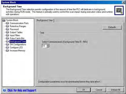
Figure 4-19 Communications Background Time
42
The S7-200 Allows You to Set the States of Digital Outputs for Stop Mode
The output table of the S7-200 allows you to determine whether to set the state of the digital output points to known values upon a transition to the STOP mode, or to leave the outputs in the state they were in before the transition to the STOP mode. The output table is part of the system block that is downloaded and stored in the S7-200.
- Select the View > Component > System Block menu command and select Output Table. Click on the Digital tab.
- To freeze the outputs in their last state, select the Freeze Outputs checkbox.
- To copy the table values to the outputs, enter the output table values by clicking the checkbox for each output bit you want to set to On (1) after a run-to-stop transition. The default values of the table are all zeroes.
- Click OK to save your selections.
- Download the modified system block to the S7-200.
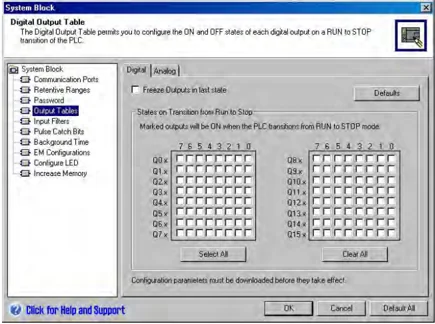
Figure 4-20 Digital Output Table
The S7-200 Allows You to Configure the Value of Analog Outputs
The Analog Output Table allows you to set analog output points to known values after a RUN-to-STOP transition, or to preserve the output values that existed before the transition to STOP mode. The Analog Output table is part of the system block that is downloaded and stored in the S7-200 CPU.
- Select the View > Component > System Block menu command and select Output Table. Click on the Analog tab.
- To freeze the outputs in their last state, select the Freeze Outputs check box.
- The Freeze Values table allows you to set the analog outputs to a known value (-32768 to 37262), on a RUN-to-STOP transition.
- Click OK to save your selections.
- Download the modified system block to the S7-200.
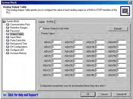
Figure 4-21 Analog Output Table
The S7-200 Allows You to Define Memory to Be Retained on Loss of Power
You can define up to six retentive ranges to select the areas of memory you want to retain through power cycles. You can define ranges of addresses in the following memory areas to be retentive: V, M, C, and T. For timers, only the retentive timers (TONR) can be retained. The default setting for the first 14 bytes of M Memory is to be non-retentive.
Only the current values for timers and counters can be retained: the timer and counter bits are not retentive.
Tip Changing the range MB0 to MB13 to be retentive enables a special feature that automatically saves these locations to the permanent memory on power down.
To define the retentive memory:
- Select the View > Component > System Block menu command and select Retentive Ranges.
- Select the ranges of memory to be retained following loss of power and click OK.
- Download the modified system block to the S7-200.
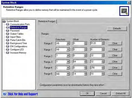
Figure 4-22 Retentive Memory
The S7-200 Allows You to Filter the Digital Inputs
The S7-200 allows you to select an input filter that defines a delay time (selectable from 0.2 ms to 12.8 ms) for some or all of the local digital input points. This delay helps to filter noise on the input wiring that could cause inadvertent changes to the states of the inputs.
The input filter is part of the system block that is downloaded and stored in the S7-200. The default filter time is 6.4 ms. As shown in Figure 4-23, each delay specification applies to groups of input points.
To configure the delay times for the input filter:
- Select the View > Component > System Block menu command and select Input Filters. Click on the Digital tab.
- Enter the amount of delay for each group of inputs and click OK.
- Download the modified system block to the S7-200.
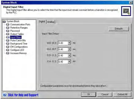
Figure 4-23 Digital Input Filter
Tip The digital input filter affects the input value as seen by instruction reads, input interrupts, and pulse catches. Depending on your filter selection, your program could miss an interrupt event or pulse catch. The high speed counters count the events on the unfiltered inputs.
44
The S7-200 Allows You to Filter the Analog Inputs
The S7-200 allows you to select software filtering on individual analog inputs. The filtered value is the average value of a preselected number of samples of the analog input. The filter specification (number of samples and deadband) is the same for all analog inputs for which filtering is enabled.
The filter has a fast response feature to allow large changes to be quickly reflected in the filter value. The filter makes a step function change to the latest analog input value when the input exceeds a specified change from the current value. This change, called the deadband, is specified in counts of the digital value of the analog input.
The default configuration is to enable filtering for all analog inputs except AIW0 and AIW2 on CPU 224XP.
- Select the View > Component > System Block menu command and select Input Filters. Click on the Analog tab.
- Select the analog inputs that you want to filter, the number of samples, and the deadband.
- Click OK.
- Download the modified system block to the S7-200.
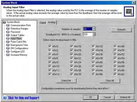
Figure 4-24 Analog Input Filter
Tip
Do not use the analog filter with modules that pass digital information or alarm indications in the analog words. Always disable analog filtering for RTD, Thermocouple, and AS-Interface Master modules.
Tip
AIW0 and AIW2 on the CPU 224XP are filtered by the analog to digital converter, and usually will not need the additional software filter.
The S7-200 Allows You to Catch Pulses of Short Duration
The S7-200 provides a pulse catch feature which can be used for some or all of the local digital input points. The pulse catch feature allows you to capture high-going pulses or low-going pulses that are of such a short duration that they would not always be seen when the S7-200 reads the digital inputs at the beginning of the scan cycle. When pulse catch is enabled for an input, a change in state of the input is latched and held until the next input cycle update. This ensures that a pulse which lasts for a short period of time is caught and held until the S7-200 reads the inputs.
You can individually enable the pulse catch operation for each of the local digital inputs.
To access the pulse catch configuration screen:
- Select the View > Component > System Block menu command and select Pulse Catch Bits.
- Click the corresponding check box and click OK.
- Download the modified system block to the S7-200.
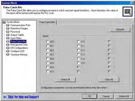
Figure 4-25 Pulse Catch
Figure 4-26 shows the basic operation of the S7-200 with and without pulse catch enabled.
 Figure 4-26 Operation of the S7-200 with the Pulse Catch Feature Enabled and Disabled
Because the pulse catch function operates on the input after it passes through the input filter, you must adjust the input filter time so that the pulse is not removed by the filter. Figure 4-27 shows a block diagram of the digital input circuit.
 Figure 4-27 Digital Input Circuit
Figure 4-28 shows the response of an enabled pulse catch function to various input conditions. If you have more than one pulse in a given scan, only the first pulse is read. If you have multiple pulses in a given scan, you should use the rising/falling edge interrupt events. (For a listing of interrupt events, see Table 6-46.)
 Figure 4-28 Responses of the Pulse Catch Function to Various Input Conditions
46
The S7-200 Provides a User-Controlled LED
The S7-200 provides an LED (SF/DIAG) that can indicate red (system fault LED) or yellow (diagnostic LED). The diagnostic LED can be illuminated under user program control, or can automatically illuminate under certain conditions: when an I/O point or data value is forced, or when a module has an I/O error.
To configure the automatic selections for the diagnostic LED:
- Select the View > Component > System Block menu command and select Configure LED.
- Click each item to either enable or disable turning on the LED when an I/O point or data value is forced, or when a module has an I/O error.
- Download the modified system block to the S7-200.
To control the state of the diagnostic LED with your user program, use the Diagnostic LED instruction in Chapter 6.
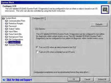
Figure 4-29 Diagnostic LED
The S7-200 Maintains a History Log of Major CPU Events
The S7-200 maintains a log that contains a time-stamped history of major CPU events, such as when power is applied, when the CPU enters RUN mode, and when fatal errors occur. Your time-of-day clock must be configured in order to get valid time and date stamps on the log entries.
To view the Event History log, select the PLC > Information menu command and select Event History.
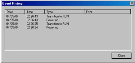
Figure 4-30 Viewing the Event History Log
The S7-200 Allows You to Increase Your Available User Program Memory
The S7-200 allows you to disable the run mode edit feature in the CPU 224, CPU 224XP, and CPU 226 in order to increase the amount of program memory available for your use. Refer to Table 1-1 to see the amount of program memory for each CPU model.
To disable the run mode edit feature, follow these steps
- Select the View > System Block menu command and select Increase Program Memory.
- Click the Increase Memory item to disable the run mode edit feature.
- Download the modified system block to the S7-200.
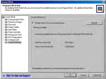
Figure 4-31 Disable Run Mode Edit
The S7-200 Provides Password Protection
All models of the S7-200 provide password protection for restricting access to specific functions.
A password authorizes access to the functions and memory: without a password, the S7-200 provides unrestricted access. When it is password protected, the S7-200 limits all restricted operations according to the configuration provided when the password was installed
The password is not case-sensitive.
As shown in Table 4-3, the S7-200 provides four levels of access restriction. Each level allows certain functions to be accessible without a password. For the four levels of access, entering the correct password provides access to the functions as noted below. The default condition for the S7-200 is level 1 (no restriction).
Entering the password over a network does not compromise the password protection for the S7-200.
You can in effect, disable the password by changing the password level 4, 3, or 2 to Level 1, since Level 1 allows all unrestricted CPU access.
Table 4-3 Restricting Access to the S7-200
Having one user authorized to access restricted functions Reset of Scan Rates in PLC information does not authorize other users to access those functions. Only one user is allowed unrestricted access to the S7-200 at a time.
Tip
After you enter the password, the authorization level for that password remains effective for up to one minute after the programming device has been disconnected from the S7-200. Always exit STEP 7-Micro/WIN before disconnecting the cable to prevent another user from accessing the privileges of the programming device.
PLC Concepts Chapter 4
Configuring a Password for the S7-200
The System Block dialog box (Figure 4-32) allows you to configure a password for the S7-200. The default condition for the S7-200 is set at Full (Level 1), no restriction.
- Select the View > Component > System Block menu command to display the System Block dialog box and select Password.
- Select the appropriate level of access for the S7-200.
- Enter and verify the password for Partial (Level 2) or Minimum (Level 3).
- Click OK.
- Download the modified system block to the S7-200.
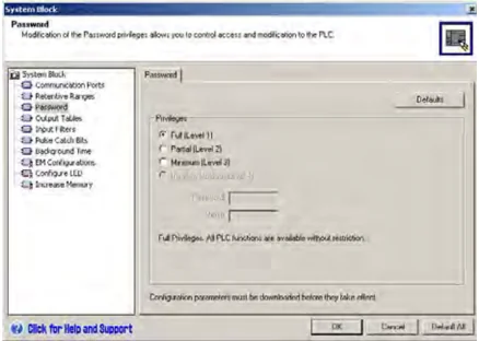
Figure 4-32 Creating a Password
Recovering from a Lost Password
If you forget the password, you must clear the memory of the S7-200 and reload your program. Clearing the memory puts the S7-200 in STOP mode and resets the S7-200 to the factory-set defaults, except for the network address, baud rate, and the time-of-day clock. To clear your program in the S7-200:
- Select the PLC > Clear menu command to display the Clear dialog box.
- Select all three blocks and confirm your action by clicking OK.
- If a password had been configured, STEP 7-Micro/WIN displays a password-authorization dialog box. To clear the password, enter CLEARPLC in the password-authorization dialog box to continue the Clear All operation. (The CLEARPLC password is not case sensitive.)
The Clear All operation does not remove the program from a memory cartridge. Since the memory cartridge stores the password along with the program, you must also reprogram the memory cartridge to remove the lost password.
Warning
Clearing the S7-200 memory causes the outputs to turn off (or in the case of an analog output, to be frozen at a specific value).
If the S7-200 is connected to equipment when you clear the memory, changes in the state of the outputs can be transmitted to the equipment. If you had configured the "safe state" for the outputs to be different from the factory settings, changes in the outputs could cause unpredictable operation of your equipment, which in turn could cause death or serious injury to personnel, and/or damage to equipment.
Always follow appropriate safety precautions and ensure that your process is in a safe state before clearing the S7-200 memory.
The S7-200 Provides Analog Adjustment Potentiometers
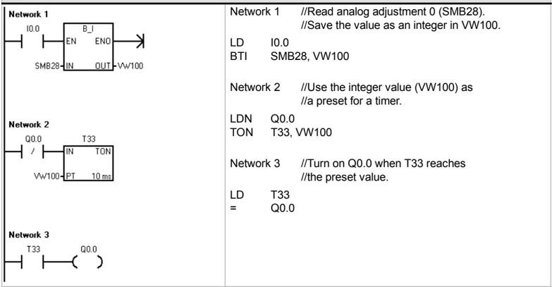
The analog adjustment potentiometers are located under the front access cover of the module. You can adjust these potentiometers to increase or decrease values that are stored in bytes of Special Memory (SMB). These read-only values can be used by the program for a variety of functions, such as updating the current value for a timer or a counter, entering or changing the preset values, or setting limits. Use a small screwdriver to make the adjustments: turn the potentiometer clockwise (to the right) to increase the value, and counterclockwise (to the left) to decrease the value.
SMB28 holds the digital value that represents the position of analog adjustment 0. SMB29 holds the digital value that represents the position of analog adjustment 1. The analog adjustment has a nominal range of 0 to 255 and a repeatability of ±2 counts.
Sample Program for Referencing the Value Entered with the Analog Adjustment Potentiometers
The S7-200 Provides High-speed I/O
High-Speed Counters
The S7-200 provides integrated high-speed counter functions that count high speed external events without degrading the performance of the S7-200. See Appendix A for the rates supported by your CPU model. Each counter has dedicated inputs for clocks, direction control, reset, and start, where these functions are supported. You can select different quadrature modes for varying the counting rate. For more information on high-speed counters, see Chapter 6.
High-Speed Pulse Output
The S7-200 supports high-speed pulse outputs, with outputs Q0.0 and Q0.1 generating either a high-speed pulse train output (PTO) or pulse width modulation (PWM).
The PTO function provides a square wave (50% duty cycle) output for a specified number of pulses (from 1 to 4,294,967,295 pulses) and a specified cycle time (in either microsecond or millisecond increments. You can program the PTO function to produce either one train of pulses or a pulse profile consisting of multiple trains of pulses. For example, you can use a pulse profile to control a stepper motor through a simple ramp up, run, and ramp down sequence or more complicated sequences.
The PWM function provides a fixed cycle time with a variable duty cycle output, with the cycle time and the pulse width specified in either microsecond or millisecond increments. When the pulse width is equal to the cycle time, the duty cycle is 100 percent and the output is turned on continuously. When the pulse width is zero, the duty cycle is 0 percent and the output is turned off.
For more information on the high-speed pulse output instruction, see Chapter 6. For more information about using PTO in open loop motion control, see Chapter 9.
Programming Concepts, Conventions, and Features
The S7-200 continuously executes your program to control a task or process. You use STEP 7-Micro/WIN to create this program and download it to the S7-200. STEP 7-Micro/WIN provides a variety of tools and features for designing, implementing, and debugging your program.
I n This C hapter
- Guidelines for Designing a Micro PLC System . . . . . . . . . . . . . . . . . . . . . . . . . . . . . . . . . . . . . . . . . . . . . . . . . . . . . . . . . . . . . . . . . . . . . . . . . . . . . . . . . . . . . . . . . . . . . . . . . . . . . . . . . . . . . . . . . . . . . . . . . . . . . . . . . . . . . . . . . . . . . . . . . . . . . . . . . . . . . . . . . . . . . . . . . . . . . . . . . . . . . . . . . . . . ........ 52
- Basic Elements of a Program . . . . . . . . . . . . . . . . . . . . . . . . . . . . . . . . . . . . . . . . . . . . . . . . . . . . . . . . . . . . . . . . . . . . . . . . . . . . . . . . . . . . . . . . . . . . . . . . . . . . . . . . . . . ........ 53
- Using STEP 7-Micro/WIN to Create Your Programs . . . . . . . . . . . . . . . . . . . . . . . . . . . . . . . . . . . . . . . . . . . . . . . . . . . . . . . . . . . . . . . . . . . . . . . . . . . . . . . . . . . . . . . . . . . . . . . . ........
Guidelines for Designing a Micro PLC System
There are many methods for designing a Micro PLC system. The following general guidelines can apply to many design projects. Of course, you must follow the directives of your own company's procedures and the accepted practices of your own training and location.
Partition Your Process or Machine
Divide your process or machine into sections that have a level of independence from each other. These partitions determine the boundaries between controllers and influence the functional description specifications and the assignment of resources.
Create the Functional Specifications
Write the descriptions of operation for each section of the process or machine. Include the following topics: I/O points, functional description of the operation, states that must be achieved before allowing action for each actuator (such as solenoids, motors, and drives), description of the operator interface, and any interfaces with other sections of the process or machine.
Design the Safety Circuits
Identify equipment requiring hard-wired logic for safety. Control devices can fail in an unsafe manner, producing unexpected startup or change in the operation of machinery. Where unexpected or incorrect operation of the machinery could result in physical injury to people or significant property damage, consideration should be given to the use of electro-mechanical overrides which operate independently of the S7-200 to prevent unsafe operations. The following tasks should be included in the design of safety circuits:
☐ Identify improper or unexpected operation of actuators that could be hazardous.
☐ Identify the conditions that would assure the operation is not hazardous, and determine how to detect these conditions independently of the S7-200.
☐ Identify how the S7-200 CPU and I/O affect the process when power is applied and removed, and when errors are detected. This information should only be used for designing for the normal and expected abnormal operation, and should not be relied on for safety purposes.
☐ Design manual or electro-mechanical safety overrides that block the hazardous operation independent of the S7-200.
☐ Provide appropriate status information from the independent circuits to the S7-200 so that the program and any operator interfaces have necessary information.
☐ Identify any other safety-related requirements for safe operation of the process.
Specify the Operator Stations
Based on the requirements of the functional specifications, create drawings of the operator stations. Include the following items:
☐ Overview showing the location of each operator station in relation to the process or machine
☐ Mechanical layout of the devices, such as display, switches, and lights, for the operator station
☐ Electrical drawings with the associated I/O of the S7-200 CPU or expansion module
52
Create the Configuration Drawings
Based on the requirements of the functional specification, create configuration drawings of the control equipment. Include the following items:
- Overview showing the location of each S7-200 in relation to the process or machine
- Mechanical layout of the S7-200 and expansion I/O modules (including cabinets and other equipment)
- Electrical drawings for each S7-200 and expansion I/O module (including the device model numbers, communications addresses, and I/O addresses)
Create a List of Symbolic Names (optional)
If you choose to use symbolic names for addressing, create a list of symbolic names for the absolute addresses. Include not only the physical I/O signals, but also the other elements to be used in your program.
Basic Elements of a Program
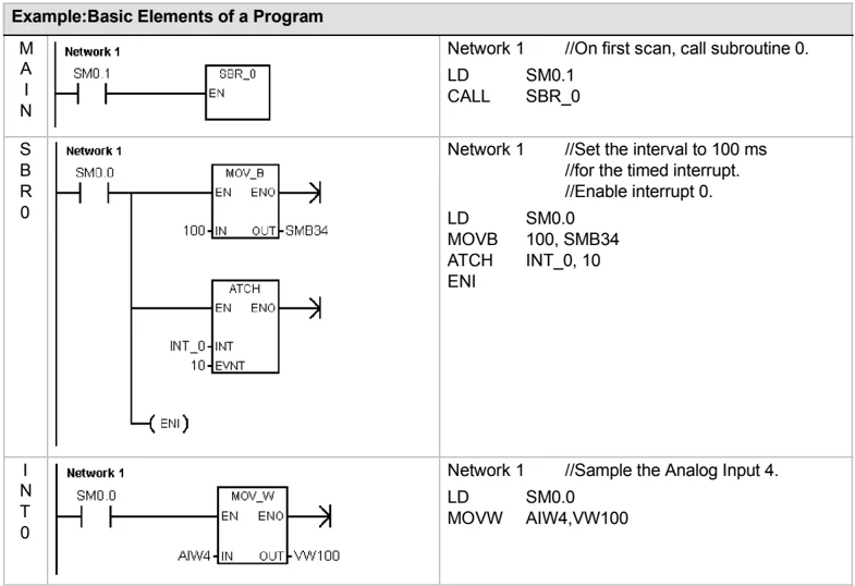
A program block is composed of executable code and comments. The executable code consists of a main program and any subroutines or interrupt routines. The code is compiled and downloaded to the S7-200; the program comments are not. You can use the organizational elements (main program, subroutines, and interrupt routines) to structure your control program.
The following example shows a program that includes a subroutine and an interrupt routine. This sample program uses a timed interrupt for reading the value of an analog input every 100 ms.
Example: Basic Elements of a Program
| M A I N | Network 1SM0.1—[ ]—[ SBR_0 ]—( EN ) | Network 1//On first scan, call subroutine 0.LD SM0.1CALL SBR_0 |
|---|---|---|
| S B R 0 | Network 1SM0.0—[ ]—[ MOV_B ]—( ENO )—>100—IN OUT—SMB34—[ ]—[ ATCH ]—( ENO )—>INT_0—INT10—EVNT—( ENI ) | Network 1//Set the interval to 100 ms//for the timed interrupt.//Enable interrupt 0.LD SM0.0MOVB 100, SMB34ATCH INT_0, 10ENI |
| I N T 0 | Network 1SM0.0—[ ]—[ MOV_W ]—( ENO )—>AIW4—IN OUT—VW100 | Network 1//Sample the Analog Input 4.LD SM0.0MOVW AIW4,VW100 |
Main Program
The main body of the program contains the instructions that control your application. The S7-200 executes these instructions sequentially, once per scan cycle. The main program is also referred to as OB1.
S7-200 Programmable Controller System Manual
Subroutines
These optional elements of your program are executed only when called: by the main program, by an interrupt routine, or by another subroutine. Subroutines are useful in cases where you want to execute a function repeatedly. Rather than rewriting the logic for each place in the main program where you want the function to occur, you can write the logic once in a subroutine and call the subroutine as many times as needed during the main program. Subroutines provide several benefits:
Using subroutines reduces the overall size of your program.
Using subroutines decreases your scan time because you have moved the code out of the main program. The S7-200 evaluates the code in the main program every scan cycle, whether the code is executed or not, but the S7-200 evaluates the code in the subroutine only when you call the subroutine, and does not evaluate the code during the scans in which the subroutine is not called.
Using subroutines creates code that is portable. You can isolate the code for a function in a subroutine, and then copy that subroutine into other programs with little or no rework.
Tip Using V memory addresses can limit the portability of your subroutine, because it is possible for V memory address assignment from one program to conflict with an assignment in another program. Subroutines that use the local variable table (L memory) for all address assignments, by contrast, are highly portable because there is no concern about address conflicts between the subroutine and another part of the program when using local variables.
I nterrupt Routines
These optional elements of your program react to specific interrupt events. You design an interrupt routine to handle a pre-defined interrupt event. Whenever the specified event occurs, the S7-200 executes the interrupt routine.
The interrupt routines are not called by your main program. You associate an interrupt routine with an interrupt event, and the S7-200 executes the instructions in the interrupt routine only on each occurrence of the interrupt event.
Tip Because it is not possible to predict when the S7-200 might generate an interrupt, it is desirable to limit the number of variables that are used both by the interrupt routine and elsewhere in the program.
Use the local variable table of the interrupt routine to ensure that your interrupt routine uses only the temporary memory and does not overwrite data used somewhere else in your program.
There are a number of programming techniques you can use to ensure that data is correctly shared between your main program and the interrupt routines. These techniques are described in Chapter 6 with the Interrupt instructions.
Other Elements of the Program
Other blocks contain information for the S7-200. You can choose to download these blocks when you download your program.
System Block The system block allows you to configure different hardware options for the S7-200.
Data Block The data block stores the values for different variables (V memory) used by your program. You can use the data block to enter initial values for the data.
54
Programming Concepts, Conventions, and Features Chapter 5
Using STEP 7-Micro/WIN to Create Your Programs
To open STEP 7-Micro/WIN, double-click on the STEP 7-Micro/WIN icon, or select the Start > SIMATIC > STEP 7 MicroWIN V4.0 menu command. As shown in Figure 5-1, the STEP 7-Micro/WIN project window provides a convenient working space for creating your control program.
The toolbars provide buttons for shortcuts to frequently used menu commands. You can view or hide any of the toolbars.
The navigation bar presents groups of icons for accessing different programming features of STEP 7-Micro/WIN.
The instruction tree displays all of the project objects and the instructions for creating your control program. You can drag and drop individual instructions from the tree into your program, or you can double-click an instruction to insert it at the current location of the cursor in the program editor.
The program editor contains the program logic and a local variable table where you can assign symbolic names for temporary local variables. Subroutines and interrupt routines appear as tabs at the bottom of the program editor window. Click on the tabs to move between the subroutines, interrupts, and the main program.
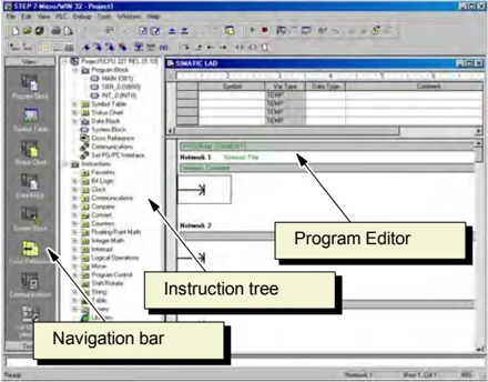
Figure 5-1 STEP 7-Micro/WIN
Program Editor STEP 7-Micro/WIN provides three editors for creating your program: Ladder Logic (LAD), Statement List (STL), and Function Block Diagram (FBD). With some restrictions, programs written in any of these program editors can be viewed and edited with the other program editors.
Features of the STL Editor
The STL editor displays the program as a text-based language. The STL editor allows you to create control programs by entering the instruction mnemonics. The STL editor also allows you to create programs that you could not otherwise create with the LAD or FBD editors. This is because you are programming in the native language of the S7-200, rather than in a graphical editor where some restrictions must be applied in order to draw the diagrams correctly. As shown in Figure 5-2, this text-based concept is very similar to assembly language programming.
The S7-200 executes each instruction in the order dictated by the program, from top to bottom, and then restarts at the top.
STL uses a logic stack to resolve the control logic. You insert the STL instructions for handling the stack operations.
Consider these main points when you select the STL editor:
LD I0.0 //Read one input A I0.1 //AND with another input = Q1.0 //Write value to output 1
Figure 5-2 Sample STL Program
- STL is most appropriate for experienced programmers.
- STL sometimes allows you to solve problems that you cannot solve very easily with the LAD or FBD editor.
- You can only use the STL editor with the SIMATIC instruction set.
- While you can always use the STL editor to view or edit a program that was created with the LAD or FBD editors, the reverse is not always true. You cannot always use the LAD or FBD editors to display a program that was written with the STL editor.
55
Features of the LAD Editor
The LAD editor displays the program as a graphical representation similar to electrical wiring diagrams. Ladder programs allow the program to emulate the flow of electric current from a power source through a series of logical input conditions that in turn enable logical output conditions. A LAD program includes a left power rail that is energized. Contacts that are closed allow energy to flow through them to the next element, and contacts that are open block that energy flow.
The logic is separated into networks. The program is executed one network at a time, from left to right and then top to bottom as dictated by the program. Figure 5-3 shows an example of a LAD program. The various instructions are represented by graphic symbols and include three basic forms.
Contacts represent logic input conditions such as switches, buttons, or internal conditions.
Coils usually represent logic output results such as lamps, motor starters, interposing relays, or internal output conditions.
Boxes represent additional instructions, such as timers, counters, or math instructions.
Consider these main points when you select the LAD editor:
☐ Ladder logic is easy for beginning programmers to use.
☐ Graphical representation is easy to understand and is popular around the world.
☐ The LAD editor can be used with both the SIMATIC and IEC 1131-3 instruction sets.
☐ You can always use the STL editor to display a program created with the SIMATIC LAD editor.
 Figure 5-3 Sample LAD Program
Features of the FBD Editor
The FBD editor displays the program as a graphical representation that resembles common logic gate diagrams. There are no contacts and coils as found in the LAD editor, but there are equivalent instructions that appear as box instructions.
Figure 5-4 shows an example of an FBD program.
FBD does not use the concept of left and right power rails; therefore, the term "power flow" is used to express the analogous concept of control flow through the FBD logic blocks.
 Figure 5-4 Sample FBD Program
The logic "1" path through FBD elements is called power flow. The origin of a power flow input and the destination of a power flow output can be assigned directly to an operand.
The program logic is derived from the connections between these box instructions. That is, the output from one instruction (such as an AND box) can be used to enable another instruction (such as a timer) to create the necessary control logic. This connection concept allows you to solve a wide variety of logic problems.
Consider these main points when you select the FBD editor:
☐ The graphical logic gate style of representation is good for following program flow.
☐ The FBD editor can be used with both the SIMATIC and IEC 1131-3 instruction sets.
☐ You can always use the STL editor to display a program created with the SIMATIC FBD editor.
Choosing Between the SIMATIC and IEC 1131-3 Instruction Sets
Most PLCs offer similar basic instructions, but there are usually small differences from vendor to vendor in appearance, operation, and so forth. Over the last several years, the International Electrotechnical Commission (IEC) has developed an emerging global standard that specifically relates to many aspects of PLC programming. This standard encourages different PLC manufacturers to offer instructions that are the same in both appearance and operation.
Your S7-200 offers two instruction sets that allow you to solve a wide variety of automation tasks. The IEC instruction set complies with the IEC 1131-3 standard for PLC programming, and the SIMATIC instruction set is designed specifically for the S7-200.
Tip When STEP 7-Micro/WIN is set to the IEC mode, it displays a red diamond (♦) in the Instruction Tree beside the instructions that are not defined by the IEC 1131-3 standard.
There are a few key differences between the SIMATIC instruction set and the IEC instruction set:
The IEC instruction set is restricted to those instructions that are standard among PLC vendors. Some instructions that are normally included in the SIMATIC set are not standard instructions in the IEC 1131-3 specification. These are still available for use as non-standard instructions, but if you use them, the program is no longer strictly IEC 1131-3 compatible.
Some IEC box instructions accept multiple data formats. This practice is often referred to as overloading. For example, rather than have separate ADD_I (Add Integer) and ADD_R (Add Real), math boxes, the IEC ADD instruction examines the format of the data being added and automatically chooses the correct instruction in the S7-200. This can save valuable program design time.
When you use the IEC instructions, the instruction parameters are automatically checked for the proper data format, such as a signed integer versus an unsigned integer. For example, an error results if you try to enter an integer value for an instruction that expected a bit value (on/off). This feature helps to minimize programming syntax errors.
Consider these points when you select either the SIMATIC or the IEC instruction set:
SIMATIC instructions usually have the shortest execution times. Some IEC instructions might have longer execution times.
Some IEC instructions, such as timers, counters, multiply, and divide, operate differently than their SIMATIC counterparts.
You can use all three program editors (LAD, STL, FBD) with the SIMATIC instruction set. You can use only the LAD and FBD program editors for IEC instructions.
The operation of the IEC instructions is standard for different brands of PLCs, and the knowledge about creating an IEC-compliant program can be leveraged across PLC platforms.
While the IEC standard defines fewer instructions than are available in the SIMATIC instruction set, you can always include SIMATIC instructions in your IEC program.
IEC 1131-3 specifies that variables must be declared with a type, and supports system checking of data type.
Understanding the Conventions Used by the Program Editors
STEP 7-Micro/WIN uses the following conventions in all of the program editors:
A # in front of a symbol name (#var1) indicates that the symbol is of local scope.
For IEC instructions, the % symbol indicates a direct address.
The operand symbol “?..?” or “????” indicates that an operand configuration is required.
LAD programs are divided into segments called networks. A network is an ordered arrangement of contacts, coils, and boxes that are all connected to form a complete circuit: no short circuits, no open circuits, and no reverse power flow conditions exist. STEP 7-Micro/WIN allows you to create comments for your LAD program on a network-by-network basis. FBD programming uses the network concept for segmenting and commenting your program.
STL programs do not use networks; however, you can use the NETWORK keyword to segment your program.
Conventions Specific to the LAD Editor
In the LAD editor, you can use the F4, F6, and F9 keys on your keyboard to access contact, box, and coil instructions. The LAD editor uses the following conventions:
The symbol “—->” is an open circuit or a required power flow connection.
The symbol “→” indicates that the output is an optional power flow for an instruction that can be cascaded or connected in series.
The symbol “>>” indicates that you can use power flow.
Conventions Specific to the FBD Editor
In the FBD editor, you can use the F4, F6, and F9 keys on your keyboard to access AND, OR, and box instructions. The FBD editor uses the following conventions:
The symbol “—->” on an EN operand is a power flow or operand indicator. It can also depict an open circuit or a required power flow connection.
The symbol “→” indicates that the output is an optional power flow for an instruction that can be cascaded or connected in series.
The symbols “<<” and “>>” indicate that you can use either a value or power flow.
Negation bubbles: The logical NOT condition or inverted condition of the operand or power flow is shown by the small circle on the input. In Figure 5-5, Q0.0 is equal to the NOT of I0.0 AND I0.1. Negation bubbles are only valid for Boolean signals, which can be specified as parameters or power flow.
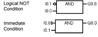
Immediate indicators: As shown in Figure 5-5, the FBD editor displays an immediate condition of a Boolean operand with a vertical line on the input to an FBD instruction. The immediate indicator causes an immediate read from the specified physical input. Immediate operators are only valid for physical inputs.
Box with no input or output: A box with no input indicates an instruction that is independent of power flow.
Tip The number of operands can be expanded up to 32 inputs for AND and OR instructions. To add or subtract operand tics, use the “+” and “–” keys on your keyboard.
General Conventions of Programming for an S7-200
EN/ENO Definition
EN (Enable IN) is a Boolean input for boxes in LAD and FBD. Power flow must be present at this input for the box instruction to be executed. In STL, the instructions do not have an EN input, but the top of stack value must be a logic "1" for the corresponding STL instruction to be executed.
ENO (Enable Out) is a Boolean output for boxes in LAD and FBD. If the box has power flow at the EN input and the box executes its function without error, then the ENO output passes power flow to the next element. If an error is detected in the execution of the box, then power flow is terminated at the box that generated the error.
In STL, there is no ENO output, but the STL instructions that correspond to the LAD and FBD instructions with ENO outputs do set a special ENO bit. This bit is accessible with the AND ENO (AENO) instruction and can be used to generate the same effect as the ENO bit of a box.
Tip The EN/ENO operands and data types are not shown in the valid operands table for each instruction because the operands are the same for all LAD and FBD instructions. Table 5-1 lists these operands and data types for LAD and FBD. These operands apply to all LAD and FBD instructions shown in this manual.
Table 5-1 EN/ENO Operands and Data Types for LAD and FBD
Conditional/Unconditional Inputs
In LAD and FBD, a box or a coil that is dependent upon power flow is shown with a connection to any element on the left side. A coil or box that is independent of power flow is shown with a connection directly to the left power rail. Table 5-2 shows an example of both a conditional and an unconditional input.
Table 5-2 Representation of Conditional and Unconditional Inputs
Instructions without Outputs
Boxes that cannot cascade are drawn with no Boolean outputs. These include the Subroutine Call, Jump, and Conditional Return instructions. There are also ladder coils that can only be placed on the left power rail. These include the Label, Next, Load SCR, Conditional SCR End, and SCR End instructions. These are shown in FBD as boxes and are distinguished with unlabeled power inputs and no outputs.
Compare Instructions
The compare instruction is executed regardless of the state of power flow. If power flow is false, the output is false. If power flow is true, the output is set depending upon the result of the compare. SIMATIC FBD, IEC Ladder, and IEC FBD compare instructions are shown as boxes, although the operation is performed as a contact.
Using Wizards To Help You Create Your Control Program
STEP 7-Micro/WIN provides wizards to make aspects of your programming easier and more automatic. In Chapter 6, instructions that have an associated wizard are identified by the following Instruction Wizard icon:
 Instruction
Wizard
Handling Errors in the S7-200
The S7-200 classifies errors as either fatal errors or non-fatal errors. You can view the error codes that were generated by an error by selecting the PLC > Information menu command.
Figure 5-6 shows the PLC Information dialog box that displays the error code and the description of the error.
The Last Fatal field shows the previous fatal error code generated by the S7-200. This value is retained over power cycles if the RAM is retained. This location is cleared either whenever all memory of the S7-200 is cleared or if the RAM is not retained after a prolonged power outage.
The Total Fatal field is the count of fatal errors generated by the S7-200 since the last time the S7-200 had all memory areas cleared. This value is retained over power cycles if the RAM is retained. This location is cleared whenever all memory of the S7-200 is cleared, or when the RAM is not retained after a prolonged power outage.
Appendix C lists the S7-200 error codes, and Appendix D describes the special memory (SM) bits, which can be used for monitoring errors.
 Figure 5-6 PLC Information Dialog Box
Non-Fatal Errors
Non-fatal errors are those indicating problems with the construction of the user program, with the execution of an instruction in the user program, and with expansion I/O modules. You can use STEP 7-Micro/WIN to view the error codes that were generated by the non-fatal error. There are three basic categories of non-fatal errors.
Program-compile errors
The S7-200 compiles the program as it downloads. If the S7-200 detects that the program violates a compilation rule, the download is aborted and an error code is generated. (A program that was already downloaded to the S7-200 would still exist in the permanent memory and would not be lost.) After you correct your program, you can download it again. Refer to Appendix C for a list of compile rule violations.
I/O errors
At startup, the S7-200 reads the I/O configuration from each module. During normal operation, the S7-200 periodically checks the status of each module and compares it against the configuration obtained during startup. If the S7-200 detects a difference, the S7-200 sets the configuration error bit in the module error register. The S7-200 does not read input data from or write output data to that module until the module configuration again matches the one obtained at startup.
60
The module status information is stored in special memory (SM) bits. Your program can monitor and evaluate these bits. Refer to Appendix D for more information about the SM bits used for reporting I/O errors. SM5.0 is the global I/O error bit and remains set while an error condition exists on an expansion module.
Program execution errors
Your program can create error conditions while being executed. These errors can result from improper use of an instruction or from the processing of invalid data by an instruction. For example, an indirect-address pointer that was valid when the program compiled could be modified during the execution of the program to point to an out-of-range address. This is an example of a run-time programming problem. SM4.3 is set upon the occurrence of a run-time programming problem and remains set while the S7-200 is in RUN mode. (Refer to Appendix C for the list of run-time programming problems). Program execution error information is stored in special memory (SM) bits. Your program can monitor and evaluate these bits. Refer to Appendix D for more information about the SM bits used for reporting program execution errors.
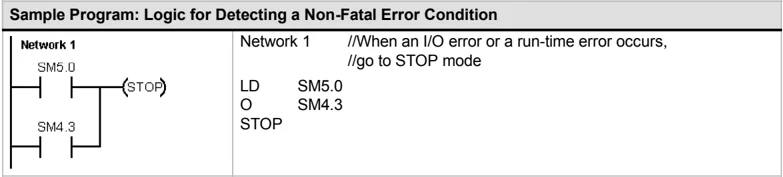
The S7-200 does not change to STOP mode when it detects a non-fatal error. It only logs the event in SM memory and continues with the execution of your program. However, you can design your program to force the S7-200 to STOP mode when a non-fatal error is detected. The following sample program shows a network of a program that is monitoring two of the global non-fatal error bits and changes the S7-200 to STOP whenever either of these bits turns on.
| Sample Program: Logic for Detecting a Non-Fatal Error Condition | |
|---|---|
| Network 1SM5.0SM4.3 | Network 1 //When an I/O error or a run-time error occurs,//go to STOP modeLD SM5.0O SM4.3STOP |
Fatal Errors
Fatal errors cause the S7-200 to stop the execution of your program. Depending upon the severity of the fatal error, it can render the S7-200 incapable of performing any or all functions. The objective for handling fatal errors is to bring the S7-200 to a safe state from which the S7-200 can respond to interrogations about the existing error conditions. When a fatal error is detected, the S7-200 changes to STOP mode, turns on the SF/DIAG (Red) and the STOP LED, overrides the output table, and turns off the outputs. The S7-200 remains in this condition until the fatal error condition is corrected.
Once you have made the changes to correct the fatal error condition, use one of the following methods to restart the S7-200:
- Turn the power off and then on.
- Change the mode switch from RUN or TERM to STOP.
- Select the PLC > Power-Up Reset menu command from STEP 7-Micro/WIN to restart the S7-200. This forces the S7-200 to restart and clear any fatal errors.
Restarting the S7-200 clears the fatal error condition and performs power-up diagnostic testing to verify that the fatal error has been corrected. If another fatal error condition is found, the S7-200 again sets the fault LED, indicating that an error still exists. Otherwise, the S7-200 begins normal operation.
Some error conditions can render the S7-200 incapable of communication. In these cases, you cannot view the error code from the S7-200. These types of errors indicate hardware failures that require the S7-200 to be repaired; they cannot be fixed by changes to the program or clearing the memory of the S7-200.