Copy Substring from String
The Copy Substring from String instruction (SSCPY) copies the specified number of characters N from the string specified by IN, starting at the index INDX, to a new string specified by OUT.
Error conditions that set ENO = 0 ■ 0006 (indirect address) ■ 0091 (range error) ■ 009B (index=0)
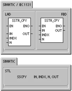
Table 6-66 Valid Operands for the Copy Substring from String Instructions \begin{tabular}{|l|l|l|} \hline Inputs/Outputs & Data Types & Operands \ \hline IN & STRING & VB, LB, *VD, *LD, *AC, Constant String \ \hline OUT & STRING & VB, LB, *VD, *LD, *AC \ \hline INDX, N & BYTE & IB, QB, VB, MB, SMB, SB, LB, AC, *VD, *LD, *AC, Constant \ \hline \end{tabular}
Example: Copy Substring Instruction
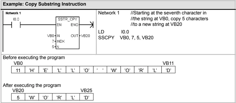
Before executing the program VB0 \begin{tabular}{|c|c|c|c|c|c|c|c|c|c|c|} \hline 11 & 'H' & 'E' & 'L' & 'L' & 'O' & ' ' & 'W' & 'O' & 'R' & 'L' & 'D' \ \hline \end{tabular} VB11
After executing the program VB20 \begin{tabular}{|c|c|c|c|c|} \hline 5 & 'W' & 'O' & 'R' & 'L' & 'D' \ \hline \end{tabular} VB25
186
Find String Within String
The Find String Within String instruction (SFND) searches for the first occurrence of the string IN2 within the string IN1. The search begins at the starting position specified by OUT (which must be in range 1 through the string length). If a sequence of characters is found that matches exactly the string IN2, the position of the first character in the sequence for the string is written to OUT. If the string IN2 was not found in the string IN1, the instruction OUT is set to 0.
Error conditions that set ENO = 0
- 0006 (indirect address)
- 0091 (range error)
- 009B (index=0)
Find First Character Within String
The Find First Character Within String instruction (CFND) searches the string IN1 for the first occurrence of any character from the character set described in the string IN2. The search begins at starting position OUT (which must be in range 1 through the string length). If a matching character is found, the position of the character is written to OUT. If no matching character is found, OUT is set to 0.
Error conditions that set ENO = 0
- 0006 (indirect address)
- 0091 (range error)
- 009B (index=0)
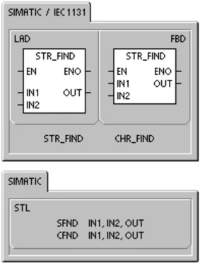
Table 6-67 Valid Operands for Find String Within String and Find First Character Within String Instructions
S7-200 Programmable Controller System Manual
Example: Find String Within String Instruction
The following example uses a string stored at VB0 as a command for turning a pump on or off. A string 'On' is stored at VB20, and a string 'Off' is stored at VB30. The result of the Find String Within String instruction is stored in AC0 (the OUT parameter). If the result is not 0, then the string 'On' was found in the command string (VB12).
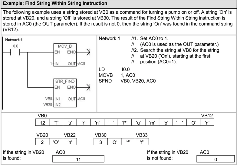
| VB0 | VB12 | ||||||||||||
|---|---|---|---|---|---|---|---|---|---|---|---|---|---|
| 12 | 'T' | 'u' | 'r' | 'n' | ' ' | 'P' | 'u' | 'm' | 'p' | ' ' | 'O' | 'n' |
| VB20 | VB22 | VB30 | VB33 | ||||
|---|---|---|---|---|---|---|---|
| 2 | 'O' | 'n' | 3 | 'O' | 'f' | 'f' |
If the string in VB20 is found: AC0 11
If the string in VB20 is not found: AC0 0
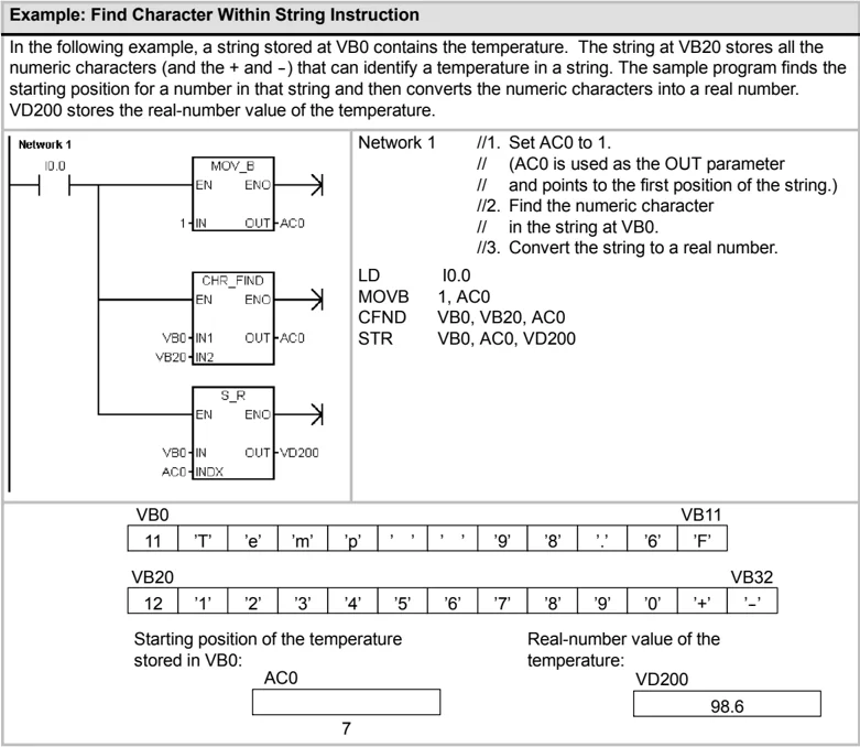
Example: Find Character Within String Instruction
In the following example, a string stored at VB0 contains the temperature. The string at VB20 stores all the numeric characters (and the + and -) that can identify a temperature in a string. The sample program finds the starting position for a number in that string and then converts the numeric characters into a real number. VD200 stores the real-number value of the temperature.
| VB0 | VB11 | ||||||||||||
|---|---|---|---|---|---|---|---|---|---|---|---|---|---|
| 11 | 'T' | 'e' | 'm' | 'p' | ' ' | ' ' | '9' | '8' | '.' | '6' | 'F' |
| VB20 | VB32 | ||||||||||||
|---|---|---|---|---|---|---|---|---|---|---|---|---|---|
| 12 | '1' | '2' | '3' | '4' | '5' | '6' | '7' | '8' | '9' | '0' | '+' | '-' |
Starting position of the temperature stored in VB0: AC0 7
Real-number value of the temperature: VD200 98.6
Table Instructions
Add To Table
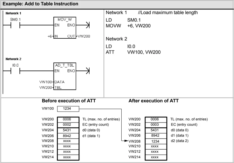
The Add To Table instruction adds word values (DATA) to a table (TBL). The first value of the table is the maximum table length (TL). The second value is the entry count (EC), which specifies the number of entries in the table. New data are added to the table after the last entry. Each time new data are added to the table, the entry count is incremented.
A table can have up to 100 data entries.
Error conditions that set ENO = 0
- SM1.4 (table overflow)
- 0006 (indirect address)
- 0091 (operand out of range)
SM bits affected:
- SM1.4 is set to 1 if you try to overfill the table
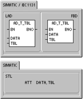
Table 6-68 Valid Operands for the Table Instructions
Example: Add to Table Instruction
First-In-First-Out and Last-In-First-Out
A table can have up to 100 data entries.
First-In-First-Out
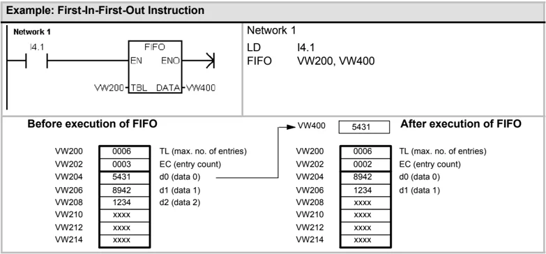
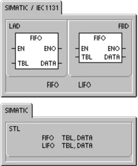
The First-In-First-Out instruction (FIFO) moves the oldest (or first) entry in a table to the output memory address by removing the first entry in the table (TBL) and moving the value to the location specified by DATA. All other entries of the table are shifted up one location. The entry count in the table is decremented for each instruction execution.
Last-In-First-Out
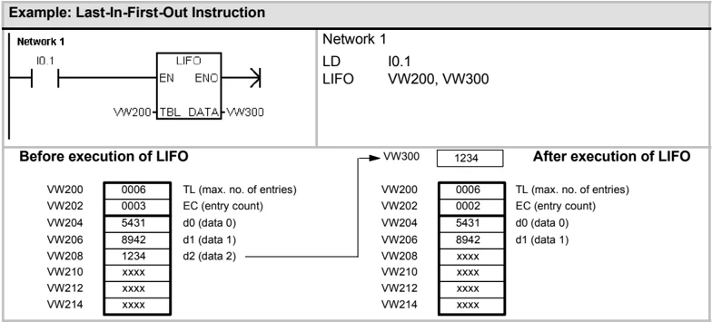
The Last-In-First-Out instruction (LIFO) moves the newest (or last) entry in the table to the output memory address by removing the last entry in the table (TBL) and moving the value to the location specified by DATA. The entry count in the table is decremented for each instruction execution.
Error conditions that set ENO = 0
- SM1.5 (empty table)
- 0006 (indirect address)
- 0091 (operand out of range)
SM bits affected:
- SM1.5 is set to 1 if you try to remove an entry from an empty table
Table 6-69 Valid Operands for the First-In-First-Out and Last-In-First-Out Instructions
| Inputs/Outputs | Data Types | Operands |
|---|---|---|
| TBL | WORD | IW, QW, VW, MW, SMW, SW, T, C, LW, *VD, *LD, *AC |
| DATA | INT | IW, QW, VW, MW, SMW, SW, T, C, LW, AC, AQW, *VD, *LD, *AC |
Example: First-In-First-Out Instruction
190
S7-200 Instruction Set Chapter 6
Example: Last-In-First-Out Instruction
| Network 1 | Network 1 |
|---|---|
| IO.1ENENDVW200 TBL_DATA VW300 | LD IO.1LIFO VW200, VW300 |
Before execution of LIFO
| VW200 | 0006 | TL (max. no. of entries) |
|---|---|---|
| VW202 | 0003 | EC (entry count) |
| VW204 | 5431 | d0 (data 0) |
| VW206 | 8942 | d1 (data 1) |
| VW208 | 1234 | d2 (data 2) |
| VW210 | xxxx | |
| VW212 | xxxx | |
| VW214 | xxxx |
After execution of LIFO
| VW200 | 0006 | TL (max. no. of entries) |
|---|---|---|
| VW202 | 0002 | EC (entry count) |
| VW204 | 5431 | d0 (data 0) |
| VW206 | 8942 | d1 (data 1) |
| VW208 | xxxx | |
| VW210 | xxxx | |
| VW212 | xxxx | |
| VW214 | xxxx |
VW300 1234
191
Memory Fill
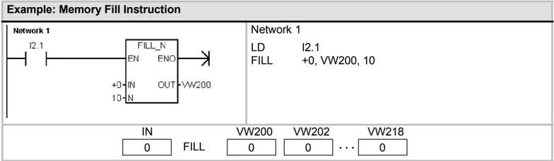
The Memory Fill instruction (FILL) writes N consecutive words, beginning at address OUT, with the word value contained in address IN.
N has a range of 1 to 255.
Error conditions that set ENO = 0
- 0006 (indirect address)
- 0091 (operand out of range)
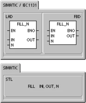
Table 6-70 Valid Operands for the Memory Fill Instruction \begin{tabular}{|l|l|l|} \hline Inputs/Outputs & Data Types & Operands \ \hline IN & INT & IW, QW, VW, MW, SMW, SW, T, C, LW, AC, AIW, *VD, *LD, *AC, Constant \ \hline N & BYTE & IB, QB, VB, MB, SMB, SB, LB, AC, *VD, *LD, *AC, Constant \ \hline OUT & INT & IW, QW, VW, MW, SMW, SW, T, C, LW, AQW, *VD, *LD, *AC \ \hline \end{tabular}
Example: Memory Fill Instruction
192
S7-200 Instruction Set Chapter 6
Table Find
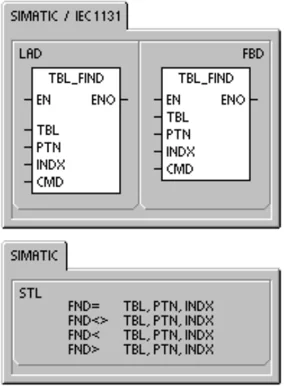
The Table Find instruction (FND) searches a table for data that matches certain criteria. The Table Find instruction searches the table TBL, starting with the table entry INDX, for the data value or pattern PTN that matches the search criteria defined by CMD. The command parameter CMD is given a numeric value of 1 to 4 that corresponds to =, <>, <, and >, respectively.
If a match is found, the INDX points to the matching entry in the table. To find the next matching entry, the INDX must be incremented before invoking the Table Find instruction again. If a match is not found, the INDX has a value equal to the entry count.
A table can have up to 100 data entries. The data entries (area to be searched) are numbered from 0 to a maximum value of 99.
Error conditions that set ENO = 0
- 0006 (indirect address)
- 0091 (operand out of range)
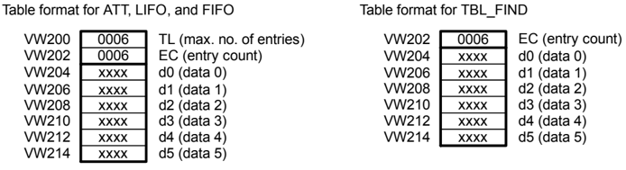
Table 6-71 Valid Operands for the Table Find Instruction
| Inputs/Outputs | Data Types | Operands |
|---|---|---|
| TBL | WORD | IW, QW, VW, MW, SMW, T, C, LW, *VD, *LD, *AC |
| PTN | INT | IW, QW, VW, MW, SMW, SW, T, C, LW, AC, AIW, *VD, *LD, *AC, Constant |
| INDX | WORD | IW, QW, VW, MW, SMW, SW, T, C, LW, AC, *VD, *LD, *AC |
| CMD | BYTE | (Constant) 1: Equal (=), 2: Not Equal (<>), 3: Less Than (<), 4: Greater Than (>) |
Tip
When you use the Table Find instruction with tables generated with the Add to Table, Last-In-First-Out, and First-In-First-Out instructions, the entry count and the data entries correspond directly. The maximum-number-of-entries word required for the Add to Table, Last-In-First-Out, or First-In-First-Out instructions is not required by the Table Find instruction. See Figure 6-36.
Consequently, you should set the TBL operand of a Find instruction to one-word address (two bytes) higher than the TBL operand of a corresponding the Add to Table, Last-In-First-Out, or First-In-First-Out instruction.
Table format for ATT, LIFO, and FIFO
| VW200 | 0006 | TL (max. no. of entries) | | VW202 | 0006 | EC (entry count) | | VW204 | xxxx | d0 (data 0) | | VW206 | xxxx | d1 (data 1) | | VW208 | xxxx | d2 (data 2) | | VW210 | xxxx | d3 (data 3) | | VW212 | xxxx | d4 (data 4) | | VW214 | xxxx | d5 (data 5) |
Table format for TBL_FIND
| VW202 | 0006 | EC (entry count) | | VW204 | xxxx | d0 (data 0) | | VW206 | xxxx | d1 (data 1) | | VW208 | xxxx | d2 (data 2) | | VW210 | xxxx | d3 (data 3) | | VW212 | xxxx | d4 (data 4) | | VW214 | xxxx | d5 (data 5) |
Figure 6-36 Different Table Formats between the Table Find Instruction and the ATT, LIFO, and FIFO Instructions
193
S7-200 Programmable Controller System Manual
Example: Table Find Instruction
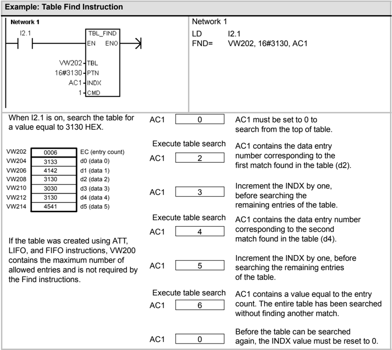
When I2.1 is on, search the table for a value equal to 3130 HEX.
VW202 0006 EC (entry count) VW204 3133 d0 (data 0) VW206 4142 d1 (data 1) VW208 3130 d2 (data 2) VW210 3030 d3 (data 3) VW212 3130 d4 (data 4) VW214 4541 d5 (data 5)
If the table was created using ATT, LIFO, and FIFO instructions, VW200 contains the maximum number of allowed entries and is not required by the Find instructions.
AC 1 0 AC 1 must be set to 0 to search from the top of table.
Execute table search AC 1 2 AC 1 contains the data entry number corresponding to the first match found in the table (d2).
AC 1 3 Increment the INDX by one, before searching the remaining entries of the table.
Execute table search AC 1 4 AC 1 contains the data entry number corresponding to the second match found in the table (d4).
AC 1 5 Increment the INDX by one, before searching the remaining entries of the table.
Execute table search AC 1 6 AC 1 contains a value equal to the entry count. The entire table has been searched without finding another match.
AC 1 0 Before the table can be searched again, the INDX value must be reset to 0.
194
S7-200 Instruction Set Chapter 6
Example: Creating a Table
The following program creates a table with 20 entries. The first memory location of the table contains the length of the table (in this case 20 entries). The second memory location shows the current number of table entries. The other locations contain the entries. A table can have up to 100 entries. It does not include the parameters defining the maximum length of the table or the actual number of entries (here VW0 and VW2). The actual number of entries in the table (here VW2) is automatically incremented or decremented by the CPU with every command.
Before you work with a table, assign the maximum number of table entries. Otherwise, you cannot make entries in the table. Also, be sure that all read and write commands are activated with edges.
To search the table, the index (VW106) must set to 0 before doing the find. If a match is found, the index will have the table entry number, but if no match is found, the index will match the current entry count for the table (VW2).
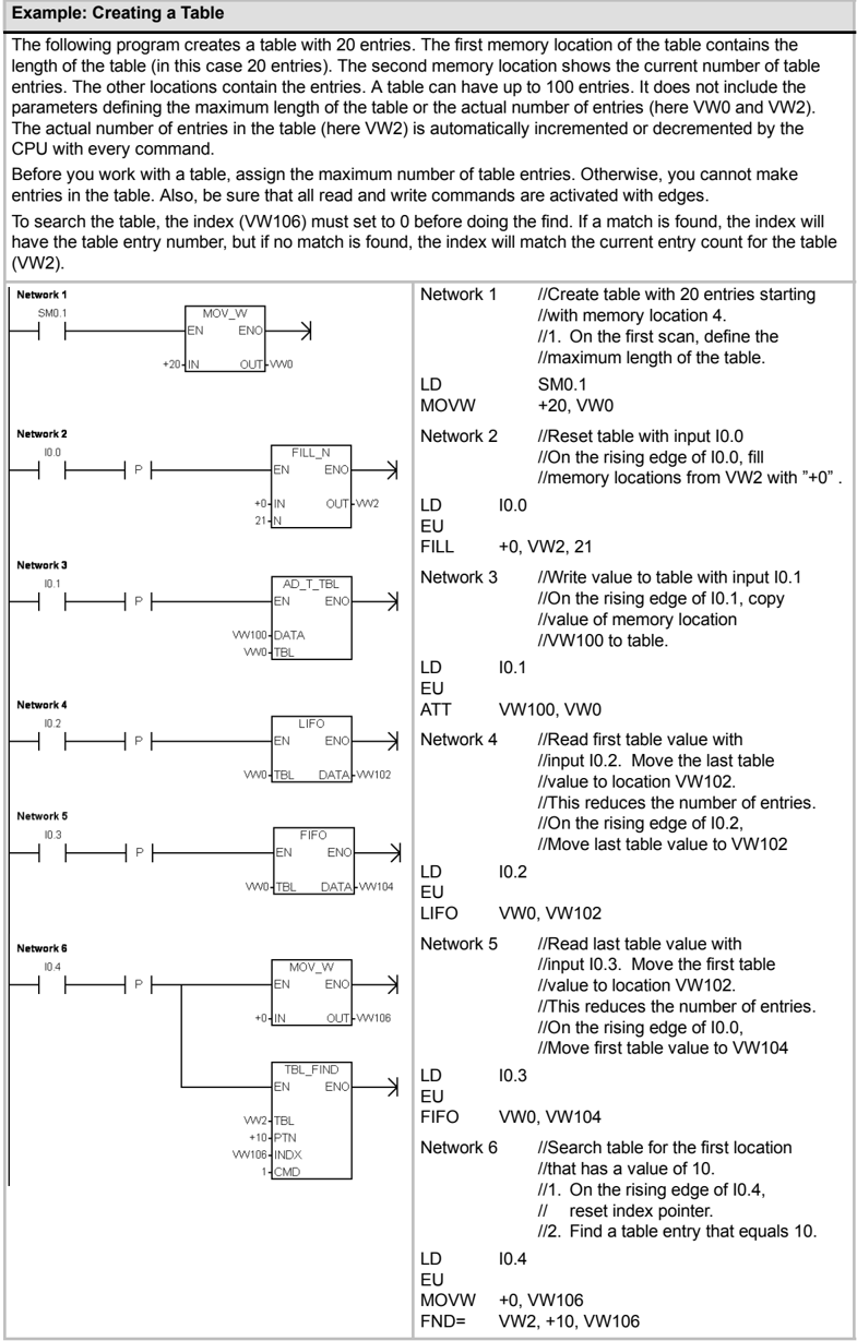
Network 1 //Create table with 20 entries starting //with memory location 4. //1. On the first scan, define the //maximum length of the table. LD SM0.1 MOVW +20, VW0
Network 2 //Reset table with input I0.0 //On the rising edge of I0.0, fill //memory locations from VW2 with "+0". LD I0.0 EU FILL +0, VW2, 21
Network 3 //Write value to table with input I0.1 //On the rising edge of I0.1, copy //value of memory location //VW100 to table. LD I0.1 EU ATT VW100, VW0
Network 4 //Read first table value with //input I0.2. Move the last table //value to location VW102. //This reduces the number of entries. //On the rising edge of I0.2, //Move last table value to VW102 LD I0.2 EU LIFO VW0, VW102
Network 5 //Read last table value with //input I0.3. Move the first table //value to location VW102. //This reduces the number of entries. //On the rising edge of I0.0, //Move first table value to VW104 LD I0.3 EU FIFO VW0, VW104
Network 6 //Search table for the first location //that has a value of 10. //1. On the rising edge of I0.4, // reset index pointer. //2. Find a table entry that equals 10. LD I0.4 EU MOVW +0, VW106 FND= VW2, +10, VW106
195
Timer Instructions
SIMATIC Timer Instructions
On-Delay Timer Retentive On-Delay Timer
The On-Delay Timer (TON) and Retentive On-Delay Timer (TONR) instructions count time when the enabling input is on. The timer number (Txx) determines the resolution of the timer, and the resolution is now shown in the instruction box.
Off-Delay Timer
The Off-Delay Timer (TOF) is used to delay turning an output off for a fixed period of time after the input turns off. The timer number (Txx) determines the resolution of the timer, and the resolution is now shown in the instruction box.
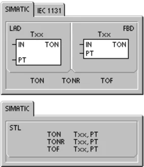
Table 6-72 Valid Operands for the SIMATIC Timer Instructions \begin{tabular}{|l|l|l|} \hline Inputs/Outputs & Data Types & Operands \ \hline Txx & WORD & Constant (T0 to T255) \ \hline IN & BOOL & I, Q, V, M, SM, S, T, C, L, Power Flow \ \hline PT & INT & IW, QW, VW, MW, SMW, SW, T, C, LW, AC, AIW, *VD, *LD, *AC, Constant \ \hline \end{tabular}
Tip You cannot share the same timer number (Txx) for an off-delay timer (TOF) and an on-delay timer (TON). For example, you cannot have both a TON T32 and a TOF T32.
As shown in Table 6-73, the three types of timers perform different types of timing tasks:
- You can use a TON for timing a single interval.
- You can use a TONR for accumulating a number of timed intervals.
- You can use a TOF for extending time past an off (or false) condition, such as for cooling a motor after it is turned off.
Table 6-73 Operations of the Timer Instructions \begin{tabular}{|l|l|l|l|} \hline Type & Current >= Preset & State of the Enabling Input (IN) & Power Cycle/First Scan \ \hline TON & Timer bit on \newline Current continues counting \newline to 32,767 & ON: Current value counts time \newline OFF: Timer bit off, current value = 0 & Timer bit off \newline Current value = 0 \ \hline TONR & Timer bit on \newline Current continues counting \newline to 32,767 & ON: Current value counts time \newline OFF: Timer bit and current value \newline maintain last state & Timer bit off \newline Current value can be \newline maintained$^1$ \ \hline TOF & Timer bit off \newline Current = Preset, stops \newline counting & ON: Timer bit on, current value = 0 \newline OFF: Timer counts after on-to-off \newline transition & Timer bit off \newline Current value = 0 \ \hline \end{tabular}
$^1$ The retentive timer current value can be selected for retention through a power cycle. See Chapter 4 for information about memory retention for the S7-200 CPU.
S7-200 Instruction Set Chapter 6
 Refer to the Programming Tips on the documentation CD for a sample program that uses the on-delay timer (TON). See Tip 31
The TON and TONR instructions count time when the enabling input is on. When the current value is equal to or greater than the preset time, the timer bit is on.
- The current value of a TON timer is cleared when the enabling input is off, whereas the current value of the TONR timer is maintained when the input is off.
- You can use the TONR timer to accumulate time when the input turns on and off. Use the Reset instruction (R) to clear the current value of the TONR.
- Both the TON and the TONR timers continue counting after the preset is reached, and they stop counting at the maximum value of 32,767.
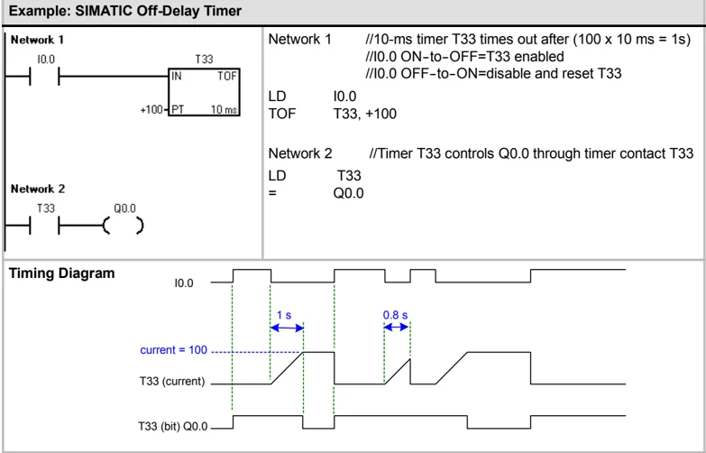
The TOF instruction is used to delay turning an output off for a fixed period of time after the input turns off. When the enabling input turns on, the timer bit turns on immediately, and the current value is set to 0. When the input turns off, the timer counts until the elapsed time reaches the preset time.
- When the preset is reached, the timer bit turns off and the current value stops incrementing; however, if the input turns on again before the TOF reaches the preset value, the timer bit remains on.
- The enabling input must make an on-to-off transition for the TOF to begin counting time intervals.
- If the TOF timer is inside an SCR region and the SCR region is inactive, then the current value is set to 0, the timer bit is turned off, and the current value does not increment.
Tip You can reset a TONR only by using the Reset (R) instruction. You can also use the Reset instruction to reset any TON or TOF. The Reset instruction performs the following operations:
- Timer Bit = off
- Timer Current = 0
After a reset, TOF timers require the enabling input to make the transition from on to off in order for the timer to restart.
Determining the Resolution of the Timer
Timers count time intervals. The resolution (or time base) of the timer determines the amount of time in each interval. For example, a TON with a resolution of 10 ms counts the number of 10-ms intervals that elapse after the TON is enabled: a count of 50 on a 10-ms timer represents 500 ms. The SIMATIC timers are available in three resolutions: 1 ms, 10 ms, and 100 ms. As shown in Table 6-74, the timer number determines the resolution of the timer.
197
Tip
To guarantee a minimum time interval, increase the preset value (PV) by 1. For example: To ensure a minimum timed interval of at least 2100 ms for a 100-ms timer, set the PV to 22.
Table 6-74 Timer Numbers and Resolutions
| Timer Type | Resolution | Maximum Value | Timer Number |
|---|---|---|---|
| TONR (retentive) | 1 ms | 32.767 s (0.546 min.) | T0, T64 |
| 10 ms | 327.67 s (5.46 min.) | T1 to T4, T65 to T68 | |
| 100 ms | 3276.7 s (54.6 min.) | T5 to T31, T69 to T95 | |
| TON, TOF (non-retentive) | 1 ms | 32.767 s (0.546 min.) | T32, T96 |
| 10 ms | 327.67 s (5.46 min.) | T33 to T36, T97 to T100 | |
| 100 ms | 3276.7 s (54.6 min.) | T37 to T63, T101 to T255 |
Understanding How Resolution Affects the Timer Action
For a timer with a resolution of 1 ms, the timer bit and the current value are updated asynchronous to the scan cycle. For scans greater than 1 ms, the timer bit and the current value are updated multiple times throughout the scan.
For a timer with a resolution of 10 ms, the timer bit and the current value are updated at the beginning of each scan cycle. The timer bit and current value remain constant throughout the scan, and the time intervals that accumulate during the scan are added to the current value at the start of each scan.
For a timer with a resolution of 100 ms, the timer bit and current value are updated when the instruction is executed; therefore, ensure that your program executes the instruction for a 100-ms timer only once per scan cycle in order for the timer to maintain the correct timing.
Example: SIMATIC On-Delay Timer
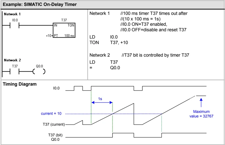
Timing Diagram
198
S7-200 Instruction Set Chapter 6
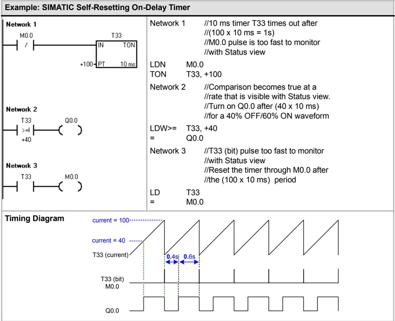
Tip To guarantee that the output of a self-resetting timer is turned on for one scan each time the timer reaches the preset value, use a normally closed contact instead of the timer bit as the enabling input to the timer.
Example: SIMATIC Self-Resetting On-Delay Timer
| Network 1 | Network 1 //10 ms timer T33 times out after // (100 x 10 ms = 1s) //M0.0 pulse is too fast to monitor //with Status view |
|---|---|
| M0.0 | LDN M0.0 |
| / | TON T33, +100 |
| T33 | |
| IN TON | |
| +100-PT 10 ms | |
| Network 2 | Network 2 //Comparison becomes true at a //rate that is visible with Status view. //Turn on Q0.0 after (40 x 10 ms) //for a 40% OFF/60% ON waveform |
| T33 | LDW>= T33, +40 |
| >= | = Q0.0 |
| +40 | |
| Q0.0 | |
| Network 3 | Network 3 //T33 (bit) pulse too fast to monitor //with Status view //Reset the timer through M0.0 after //the (100 x 10 ms) period |
| T33 | LD T33 |
| M0.0 | = M0.0 |
Timing Diagram
current = 100------------------- current = 40 ----------------- T33 (current) T33 (bit) M0.0 Q0.0
0.4s 0.6s
Example: SIMATIC Off-Delay Timer
| Network 1 | Network 1 //10-ms timer T33 times out after (100 x 10 ms = 1s) //I0.0 ON-to-OFF=T33 enabled //I0.0 OFF-to-ON=disable and reset T33 |
|---|---|
| I0.0 | LD I0.0 |
| T33 | TOF T33, +100 |
| IN TOF | |
| +100-PT 10 ms | |
| Network 2 | Network 2 //Timer T33 controls Q0.0 through timer contact T33 |
| T33 | LD T33 |
| Q0.0 | = Q0.0 |
Timing Diagram
I0.0
current = 100 ----------------- T33 (current) T33 (bit) Q0.0
1 s 0.8 s
199
S7-200 Programmable Controller System Manual
Example: SIMATIC Retentive On-Delay Timer
Network 1
 Network 1 //10 ms TONR timer T1 times out at
//PT=(100 x 10 ms=1s)
LD I0.0 TONR T1, +100
Network 2
Network 2 //T1 bit is controlled by timer T1. //Turns Q0.0 on after the timer accumulates a total //of 1 second
LD T1 = Q0.0
Network 3
Network 3 //TONR timers must be reset by a Reset instruction //with a T address. //Resets timer T1 (current and bit) when I0.1 is on.
LD I0.1 R T1, 1
Timing Diagram
200
IEC Timer Instructions
On-Delay Timer
The On-Delay Timer (TON) instruction counts time when the enabling input is on.
Off-Delay Timer
The Off-Delay Timer (TOF) delays turning an output off for a fixed period of time after the input turns off.
Pulse Timer
The Pulse Timer (TP) generates pulses for a specific duration.
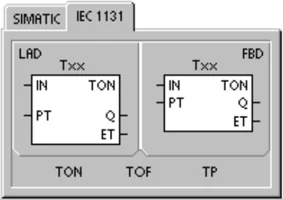
Table 6-75 Valid Operands for the IEC Timer Instructions \begin{tabular}{|l|l|l|} \hline Inputs/Outputs & Data Types & Operands \ \hline Txx & TON, TOF, TP & Constant (T32 to T63, T96 to T255) \ \hline IN & BOOL & I, Q, V, M, SM, S, T, C, L, Power Flow \ \hline PT & INT & IW, QW, VW, MW, SMW, SW, LW, AC, AIW, *VD, *LD, *AC, Constant \ \hline Q & BOOL & I, Q, V, M, SM, S, L \ \hline ET & INT & IW, QW, VW, MW, SMW, SW, LW, AC, AQW, *VD, *LD, *AC \ \hline \end{tabular}
Tip You cannot share the same timer numbers for TOF, TON, and TP. For example, you cannot have both a TON T32 and a TOF T32.
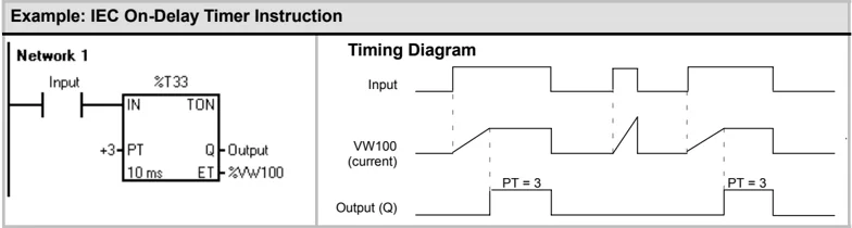
\square The TON instruction counts time intervals up to the preset value when the enabling input (IN) becomes true. When the elapsed time (ET) is equal to the Preset Time (PT), the timer output bit (Q) turns on. The output bit resets when the enabling input turns off. When the preset is reached, timing stops and the timer is disabled.
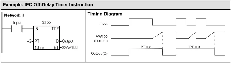
\square The TOF instruction delays setting an output to off for a fixed period of time after the input turns off. It times up to the preset value when the enabling input (IN) turns off. When the elapsed time (ET) is equal to the preset time (PT), the timer output bit (Q) turns off. When the preset is reached, the timer output bit turns off and the elapsed time is maintained until the enabling input makes the transition to on. If the enabling input sets the transition to off for a period of time shorter than the preset time, the output bit remains on.
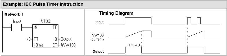
\square The TP instruction generates pulses for a specific duration. As the enabling input (IN) turns on, the output bit (Q) turns on. The output bit remains on for the pulse specified within the preset time (PT). When the elapsed time (ET) reaches preset (PT), the output bit turns off. The elapsed time is maintained until the enabling input turns off. When the output bit turns on, it remains on until the pulse time has elapsed.
Each count of the current value is a multiple of the time base. For example, a count of 50 on a 10-ms timer represents 500 ms. The IEC timers (TON, TOF, and TP) are available in three resolutions. The resolution is determined by the timer number, as shown in Table 6-76.
Table 6-76 Resolution of the IEC Timers \begin{tabular}{|l|l|l|} \hline Resolution & Maximum Value & Timer Number \ \hline 1 ms & 32.767 s (0.546 minutes) & T32, T96 \ \hline 10 ms & 327.67 s (5.46 minutes) & T33 to T36, T97 to T100 \ \hline 100 ms & 3276.7 s (54.6 minutes) & T37 to T63, T101 to T255 \ \hline \end{tabular}
Example: IEC On-Delay Timer Instruction
Example: IEC Off-Delay Timer Instruction
Example: IEC Pulse Timer Instruction
202
Interval Timers
Beginning Interval Time
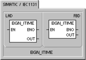
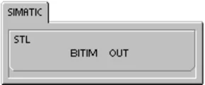
The Beginning Interval Time (BITIM) instruction reads the current value of the built-in 1 millisecond counter and stores the value in OUT. The maximum timed interval for a DWORD millisecond value is 2 raised to the 32 power or 49.7 days.
Calculate Interval Time
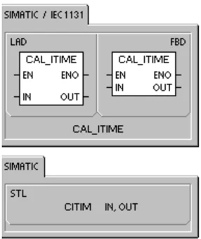
The Calculate Interval Time (CITIM) instruction calculates the time difference between the current time and the time provided in IN. The difference is stored in OUT. The maximum timed interval for a DWORD millisecond value is 2 raised to the 32 power or 49.7 days. CITIM automatically handles the one millisecond timer rollover that occurs within the maximum interval, depending on when the BITIM instruction was executed.
Table 6-77 Valid Operands for the Interval Timer Instructions \begin{tabular}{|l|l|l|} \hline Inputs/Outputs & Data Types & Operands \ \hline IN & DWORD & VD, ID, QD, MD, SMD, SD, LD, HC, AC, *VD, *LD, *AC \ \hline OUT & DWORD & VD, ID, QD, MD, SMD, SD, LD, AC, *VD, *LD, *AC \ \hline \end{tabular}
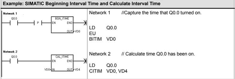
Example: SIMATIC Beginning Interval Time and Calculate Interval Time
Subroutine Instructions
The Call Subroutine instruction (CALL) transfers control to the subroutine SBR_N. You can use a Call Subroutine instruction with or without parameters. After the subroutine completes its execution, control returns to the instruction that follows the Call Subroutine.
The Conditional Return from Subroutine instruction (CRET) terminates the subroutine based upon the preceding logic.
To add a subroutine, select the Edit > Insert > Subroutine menu command.
Error conditions that set ENO = 0
- 0008 (maximum subroutine nesting exceeded)
- 0006 (indirect address)
From the main program, you can nest subroutines (place a subroutine call within a subroutine) to a depth of eight. From an interrupt routine, you cannot nest subroutines.
A subroutine call cannot be placed in any subroutine called from an interrupt routine. Recursion (a subroutine that calls itself) is not prohibited, but you should use caution when using recursion with subroutines.
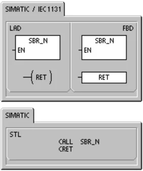
Table 6-78 Valid Operands for the Subroutine Instruction
\begin{tabular}{|l|l|p{8cm}|} \hline Inputs/Outputs & Data Types & Operands \ \hline SBR_N & WORD & Constant for CPU 221, CPU 222, CPU 224: 0 to 63 \newline for CPU 224XP and CPU 226 0 to 127 \ \hline IN & BOOL & V, I, Q, M, SM, S, T, C, L, Power Flow \ \cline{2-3} & BYTE & VB, IB, QB, MB, SMB, SB, LB, AC, *VD, *LD, *AC$^1$, constant \ \cline{2-3} & WORD, INT & VW, T, C, IW, QW, MW, SMW, SW, LW, AC, AIW, *VD, *LD, *AC$^1$, constant \ \cline{2-3} & DWORD, DINT & VD, ID, QD, MD, SMD, SD, LD, AC, HC, *VD, *LD, *AC$^1$, &VB, &IB, &QB, &MB, &T, &C, &SB, &AI, &AQ, &SMB, constant *VD, *LD, *AC, constant \ \hline IN/OUT & BOOL & V, I, Q, M, SM$^2$, S, T, C, L \ \cline{2-3} & BYTE & VB, IB, QB, MB, SMB$^2$, SB, LB, AC, *VD, *LD, *AC$^1$ \ \cline{2-3} & WORD, INT & VW, T, C, IW, QW, MW, SMW$^2$, SW, LW, AC, *VD, *LD, *AC$^1$ \ \cline{2-3} & DWORD, DINT & VD, ID, QD, MD, SMD$^2$, SD, LD, AC, *VD, *LD, *AC$^1$ \ \hline OUT & BOOL & V, I, Q, M, SM$^2$, S, T, C, L \ \cline{2-3} & BYTE & VB, IB, QB, MB, SMB$^2$, SB, LB, AC, *VD, *LD, *AC$^1$ \ \cline{2-3} & WORD, INT & VW, T, C, IW, QW, MW, SMW$^2$, SW, LW, AC, AQW, *VD, *LD, *AC$^1$ \ \cline{2-3} & DWORD, DINT & VD, ID, QD, MD, SMD$^2$, SD, LD, AC, *VD, *LD, *AC$^1$ \ \hline \end{tabular}
$^1$ Must be offset 1 or above $^2$ Must be offset 30 or above
Tip STEP 7-Micro/WIN automatically adds an unconditional return from each subroutine.
When a subroutine is called, the entire logic stack is saved, the top of stack is set to one, all other stack locations are set to zero, and control is transferred to the called subroutine. When this subroutine is completed, the stack is restored with the values saved at the point of call, and control is returned to the calling routine.
Accumulators are common to subroutines and the calling routine. No save or restore operation is performed on accumulators due to subroutine use.
When a subroutine is called more than once in the same cycle, the edge/up, edge/down, timer and counter instructions should not be used.
Calling a Subroutine With Parameters
Subroutines can contain passed parameters. The parameters are defined in the local variable table of the subroutine. The parameters must have a symbol name (maximum of 23 characters), a variable type, and a data type. Sixteen parameters can be passed to or from a subroutine.
The variable type field in the local variable table defines whether the variable is passed into the subroutine (IN), passed into and out of the subroutine (IN_OUT), or passed out of the subroutine (OUT). Table 6-79 describes the parameter types for a subroutine. To add a parameter entry, place the cursor on the variable type field of the type (IN, IN_OUT, or OUT) that you want to add. Click the right mouse button to get a menu of options. Select the Insert option and then the Row Below option. Another parameter entry of the selected type appears below the current entry.
Table 6-79 Parameter Types for a Subroutine
As shown in Figure 6-37, the data type field in the local variable table defines the size and format of the parameter. The parameter types are listed below:
BOOL: This data type is used for single bit inputs and outputs. IN3 in the following example is a Boolean input.
BYTE, WORD, DWORD: These data types identify an unsigned input or output parameter of 1, 2, or 4 bytes, respectively.
INT, DINT: These data types identify signed input or output parameters of 2 or 4 bytes, respectively.
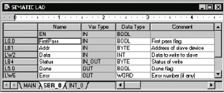
Figure 6-37 Local Variable Table
REAL: This data type identifies a single precision (4 byte) IEEE floating-point value.
STRING: This data type is used as a four-byte pointer to a string.
Power Flow: Boolean power flow is allowed only for bit (Boolean) inputs. This declaration tells STEP 7-Micro/WIN that this input parameter is the result of power flow based on a combination of bit logic instructions. Boolean power flow inputs must appear first in the local variable table before any other type input. Only input parameters are allowed to be used this way. The enable input (EN) and the IN1 inputs in the following example use Boolean logic.
Example: Subroutine Call
There are two STL examples provided. The first set of STL instructions can be displayed only in the STL editor since the BOOL parameters used as power flow inputs are not saved to L memory. The second set of STL instructions can be displayed also in the LAD and FBD editors because L memory is used to save the state of the BOOL inputs parameters that are shown as power flow inputs in LAD and FBD.
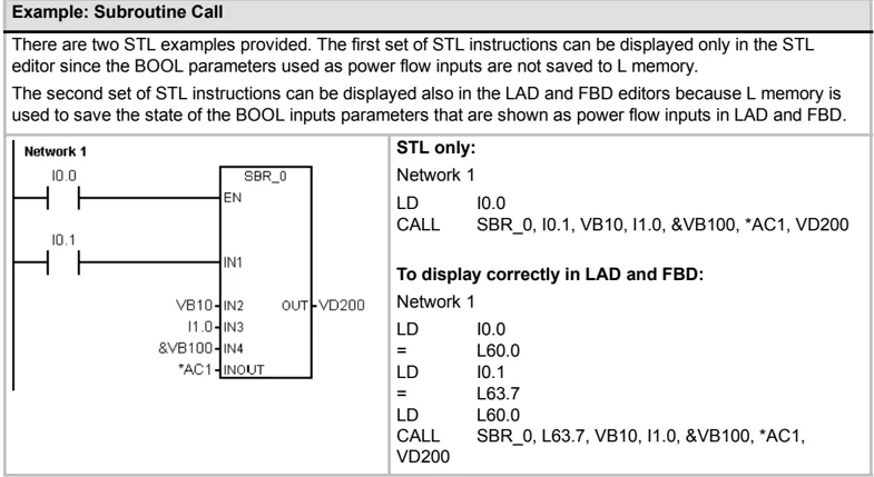
Address parameters such as IN4 (&VB100) are passed into a subroutine as a DWORD (unsigned double word) value. The type of a constant parameter must be specified for the parameter in the calling routine with a constant descriptor in front of the constant value. For example, to pass an unsigned double word constant with a value of 12,345 as a parameter, the constant parameter must be specified as DW#12345. If the constant describer is omitted from the parameter, the constant can be assumed to be a different type.
There are no automatic data type conversions performed on the input or output parameters. For example, if the local variable table specifies that a parameter has the data type REAL, and in the calling routine a double word (DWORD) is specified for that parameter, the value in the subroutine will be a double word.
When values are passed to a subroutine, they are placed into the local memory of the subroutine. The left-most column of the local variable table shows the local memory address for each passed parameter. Input parameter values are copied to the subroutine's local memory when the subroutine is called. Output parameter values are copied from the subroutine's local memory to the specified output parameter addresses when the subroutine execution is complete.
The data element size and type are represented in the coding of the parameters. Assignment of parameter values to local memory in the subroutine is as follows:
- Parameter values are assigned to local memory in the order specified by the call subroutine instruction with parameters starting at L.0.
- One to eight consecutive bit parameter values are assigned to a single byte starting with Lx.0 and continuing to Lx.7.
- Byte, word, and double word values are assigned to local memory on byte boundaries (LBx, LWx, or LDx).
In the Call Subroutine instruction with parameters, parameters must be arranged in order with input parameters first, followed by input/output parameters, and then followed by output parameters.
If you are programming in STL, the format of the CALL instruction is:
CALL subroutine number, parameter 1, parameter 2, ... , parameter
206
S7-200 Instruction Set Chapter 6
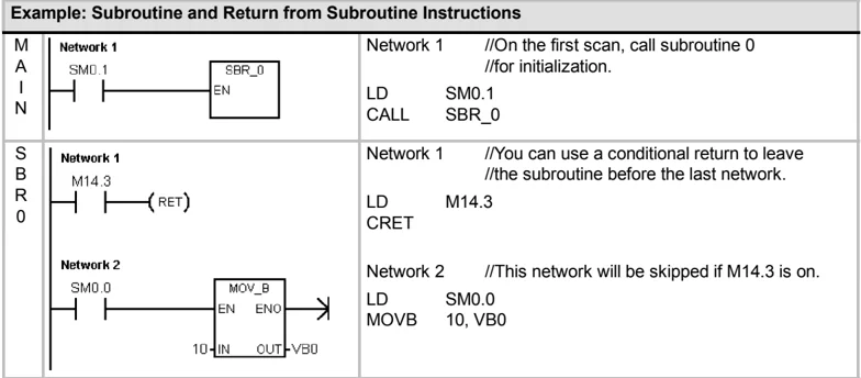
Example: Subroutine and Return from Subroutine Instructions
| M A I N | Network 1SM0.1EN | Network 1 //On the first scan, call subroutine 0//for initialization.LD SM0.1CALL SBR_0 |
|---|---|---|
| S B R 0 | Network 1M14.3(RET)Network 2SM0.0EN ENO10 IN OUT VB0 | Network 1 //You can use a conditional return to leave//the subroutine before the last network.LD M14.3CRETNetwork 2 //This network will be skipped if M14.3 is on.LD SM0.0MOVB 10, VB0 |
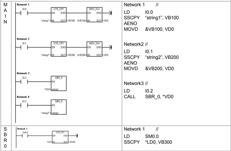
Example: Subroutine Call with strings
This example copies a different string literal to a unique address depending upon the given input. The unique address of this string is saved. The string address is then passed to the subroutine by using an indirect address. The data type of the subroutine input parameter is string. The subroutine then moves the string to a different location.
A string literal can also be passed to the subroutine. The string reference inside the subroutine is always the same.
| M A I N | Network 1I0.0STR_CPY EN END"string1" IN OUT VB100 &VB100MOV_DW EN ENDIN OUT VD0Network 2I0.1STR_CPY EN END"string2" IN OUT VB200 &VB200MOV_DW EN ENDIN OUT VD0Network 3I0.2SBR_0 EN*VD0 string1Network 4I0.3SBR_0 EN"string3" string1 | Network 1 //LD I0.0SSCPY "string1", VB100AENOMOVD &VB100, VD0Network2 //LD I0.1SSCPY "string2", VB200AENOMOVD &VB200, VD0Network3 //LD I0.2CALL SBR_0, *VD0 |
|---|---|---|
| S B R 0 | Network 1SM0.0STR_CPY EN END*LD0 IN OUT VB300 | Network 1 //LD SM0.0SSCPY *LD0, VB300 |
207
Communicating over a Network
The S7-200 is designed to solve your communications and networking needs by supporting not only the simplest of networks but also supporting more complex networks. The S7-200 also provides tools that allow you to communicate with other devices, such as printers and weigh scales which use their own communications protocols.
STEP 7-Micro/WIN makes setting up and configuring your network simple and straightforward.
I n This Chapter
- Understanding the Basics of S7-200 Network Communications . . . . . . . . . . . . . . . . . . . . . . . . . . . . . . . . . . . . . . . . . . . . . . . . . . . . . . . . . . . . . . . . . . . . . . . . . . . . . . . . . . . . . . . . . . . . . . . . . . . . . . . . . . . . . . . . . . . . . . . . . . . . . . . . ........ 210
- Selecting the Communications Protocol for Your Network . . . . . . . . . . . . . . . . . . . . . . . . . . . . . . . . . . . . . . . . . . . . . . . . . . . . . . . . . . . . . . . . . . . . . . . . . . . . . . . . . . . . . . . . . . . . . . . . . . . . . . . . . . . . . . . . . . . . . . . . . . . . . . . . . . . . . . . . . . . . . . . . . . . . . . . . . . . . . . . . . . . . . . . . . . . . . . . . . . . . . . . . . . . . . . . . . . . . . . . . . . . . . . . . . . . . . . . . . . . . . . . ........ 214
- Installing and Removing Communications Interfaces . . . . . . . . . . . . . . . . . . . . . . . . . . . . . . . . . . . . . . . . . . . . . . . . . . . . . . . . . . . . . . . . . . . . . . . . . . . . . . . . . . . . . . . . . . . . . . . . . . . . . . . . . . . . . . . . . . . . . . . . . . . . . . . . . . . . . . . . . . . . . . . . . . . . . . . . . . . . . . . . . . . . . . . . . . . . . . . . . . . . . . . . . . . . . . . . . . . . . . . . . . . . . . . . . . . . . . . . . . . . . . ........

Understanding the Basics of S7-200 Network Communications
Selecting the Communication Interface for Your Network
The S7-200 supports many different types of communication networks. The selection of a network is performed within the Set PG/PC Interface property dialog. A selected network is referred to as an Interface. The different types of interfaces available to access these communication networks are:
☐ PPI Multi-Master cables ☐ CP communication cards ☐ Ethernet communication cards
To select the communication interface for STEP 7-Micro/WIN, you perform the following steps. See Figure 7-1.
- Double-click the icon in the Communications Setup window.
- Select the interface parameter for STEP 7-Micro/WIN.
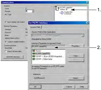
Figure 7-1 STEP 7-Micro/WIN Communications Interface
PPI Multi-Master Cables
The S7-200 supports communication through two different types of PPI Multi-Master cables. These cable types permit communication through either an RS-232 or a USB interface.
As shown in Figure 7-2, selecting the PPI Multi-Master cable type is simple. You perform the following steps:
- Click the Properties button on the Set PG/PC Interface property page.
- Click the Local Connection tab on the Properties page.
- Select the USB or the desired COM port.
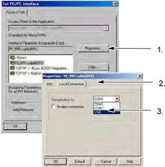
Figure 7-2 PPI Multi-Master Cable Selection
Tip Please note that only one USB cable can be used at a time.
Tip Examples in this manual use the RS-232/PPI Multi-Master cable. The RS-232/PPI Multi-Master cable replaces the previous PC/PPI cable. A USB/PPI Multi-Master cable is also available. Refer to Appendix E for order numbers.
210