(CP 243-1 IT) Internet Module Specifications
Table A-60 (CP 243-1 IT) Internet Module Order Number
| Order Number | Expansion Module | EM Inputs | EM Outputs | Removable Connector |
|---|---|---|---|---|
| 6GK7 243-1GX00-OXE0 | (CP 243-1 IT) Internet Module | - | 8¹ | No |
¹ Eight Q outputs are used as logical controls of the IT function and do not directly control any external signals.
Table A-61 (CP 243-1 IT) Internet Module General Specifications
| Order Number | Module Name and Description | Dimensions (mm) (W x H x D) | Weight | Dissipation | VDC Requirements +5 VDC | +24 VDC |
|---|---|---|---|---|---|---|
| 6GK7 243-1GX00-OXE0 | (CP 243-1 IT) Internet Module | 71.2 x 80 x 62 | approx. 150 g | 1.75 W | 55 mA | 60 mA |
Table A-62 (CP 243-1 IT) Internet Module Specifications
| General | 6GK7 243-1GX00-OXE0 |
|---|---|
| Transmission speed | 10 Mbit/s and 100 Mbits/s |
| Flash memory size | 8 Mbytes as ROM for firmware of the (CP 243-1 IT) Internet module, 8 Mbytes as RAM for the file system |
| SDRAM memory size | 16 Mbyte |
| Guaranteed life of flash memory for the file system | 1 million write or delete operations |
| Interface | Connection to Industrial Ethernet (10/100 Mbit/s) 8-pin RJ 45 socket |
| Input voltage | 20.4 to 28.8 VDC |
| Maximum connections | Maximum of 8 S7 connections (XPUT/XGET and READ/WRITE) plus 1 connection to STEP 7-Micro/WIN per (CP 243-1 IT) Internet module¹ |
| Maximum number of IT connections | 1 for FTP server 1 for FTP client 1 for e-mail client 4 for HTTP connections |
| Starting time or restart time after a reset | Approx. 10 seconds |
| User data quantities | Client: up to 212 bytes for XPUT/XGET Server: up to 222 bytes for XGET or READ up to 212 bytes for XPUT or WRITE |
| E-mail size, maximum | 1024 characters |
| File system: Path length including file size and drive names File name length Directory nesting depth | 254 characters maximum 99 characters maximum 49 maximum |
| Server ports available: HTTP FTP command channel FTP data channels for FTP server S7 connection establishment S7 server | 80 21 3100 to 3199 102 3000 to 3008 |
¹ Only one (CP 243-1 IT) Internet module should be connected per S7-200 CPU.
Technical Specifications Appendix A
The (CP 243-1 IT) Internet module is a communications processor used for connecting the S7-200 system to Industrial Ethernet (IE). The S7-200 can be remotely configured, programmed and diagnosed via Ethernet using STEP 7 Micro/WIN. The S7-200 can communicate with another S7-200, S7-300, or S7-400 controller via Ethernet. It can also communicate with an OPC server.
The IT functions of the (CP 243-1 IT) Internet module form the basis for monitoring and, if necessary, also manipulating automation systems with a WEB browser from a networked PC. Diagnostic messages can be e-mailed from a system. Using the IT functions, it is easy to exchange entire files with other computer and controller systems.
Industrial Ethernet is the network for the process control level and the cell level of the SIMATIC NET open communication system. Physically, Industrial Ethernet is an electrical network based on shielded, coaxial lines, twisted pair cables and an optical network of fiber optic conductors. Industrial Ethernet is defined by the International Standard IEEE 802.3.
S7-200 CPUs that Support Intelligent Modules
The (CP 243-1 IT) Internet module is an intelligent expansion module designed to work with the S7-200 CPUs shown in Table A-63.
Table A-63 (CP 243-1 IT) Internet Module Compatibility with S7-200 CPUs
| CPU | Description |
|---|---|
| CPU 222 Rel. 1.10 or greater | CPU 222 DC/DC/DC and CPU 222 AC/DC/Relay |
| CPU 224 Rel. 1.10 or greater | CPU 224 DC/DC/DC and CPU 224 AC/DC/Relay |
| CPU 224XP Rel. 2.00 or greater | CPU 224XP DC/DC/DC and CPU 224XP AC/DC/Relay |
| CPU 226 Rel. 1.00 or greater | CPU 226 DC/DC/DC and CPU 226 AC/DC/Relay |
The (CP 243-1 IT) Internet module has the following features:
- The (CPU 243-1 IT) Internet module is fully compatible with the (CP 243-1) Ethernet module. User programs written for the (CP 243-1) Ethernet module can also be run on the (CP 243-1 IT) Internet module.
The (CP 243-1 IT) Internet module is delivered with a preset, unique worldwide MAC address that cannot be changed.
Tip
Only one (CP 243-1 IT) Internet module should be connected per S7-200 CPU. If more than one (CP 243-1 IT) Internet module is connected, the S7-200 CPU may not operate properly.
Functions
The (CP 243-1 IT) Internet module offers the following functions:
- S7 Communication is based on TCP/IP
- IT communication
- Configuration
- Watchdog timer
- Ability of preset MAC addresses (48-bit value) to be addressed
461
S7-200 Programmable Controller System Manual
Configuration
Internet You can use the STEP 7-Micro/WIN Internet Wizard to configure the (CP 243-1 IT) Internet module to connect an S7-200 PLC to an Ethernet/Internet network. The (CP 243-1 IT) Internet module has additional web server functionality that can be configured with the Internet Wizard. To start the Internet Wizard, select the Tools > Internet Wizard menu command.
Connections
The (CP 243-1 IT) Internet module has the following connections. The connections are located under the covers of the front doors.
- Terminal block for 24 VDC supply voltage and ground connection
- 8-in RJ 45 socket for Ethernet connection
- Plug connector for I/O bus
- Integrated ribbon cable with socket for I/O bus
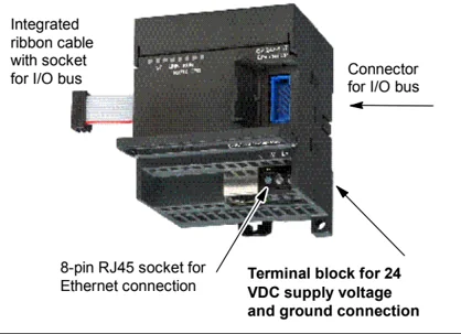
Figure A-41 Connecting the (CP 243-1 IT) Internet Module
Additional Information
For more information about the (CP 243-1 IT) Internet module, refer to the SIMATIC NET CP 243-1 IT Communications Processor for Industrial Ethernet and Information Technology Technical Manual.
462
(CP 243-2) AS-Interface Module Specifications
Table A-64 (CP 243-2) AS-Interface Module Order Number
| Order Number | Expansion Model | EM Inputs | EM Outputs | Removable Connector |
|---|---|---|---|---|
| 6GK7 243-2AX01-0XA0 | (CP 243-2) AS-Interface Module | 8 Digital and 8 Analog | 8 Digital and 8 Analog | Yes |
Table A-65 (CP 243-2) AS-Interface Module General Specifications
| Order Number | Module Name and Description | Dimensions (mm) (W x H x D) | Weight | Dissipation | +5 VDC | VDC Requirements From AS-Interface |
|---|---|---|---|---|---|---|
| 6GK7 243-2AX01-0XA0 | (CP 243-2) AS-Interface Module | 71 x 80 x 62 | approx. 250 g | 3.7 W | 220 mA | 100 mA |
Table A-66 (CP 243-2) AS-Interface Module Specifications
| General | 6GK7 243-2AX01-0XA0 |
|---|---|
| Cycle time | 5 ms with 31 slaves10 ms with 62 AS-I slaves using the extended addressing mode |
| Configuration | Set button on the front panel, or use the total configuration command (refer to the description of the AS-I commands in the CP 243-2 AS-I Interface Master manual) |
| AS-I master profiles supported | M1e |
| Attachment to the AS-I cable | Via an S 7-200 terminal block. Permitted current loading from terminal 1 to 3 or from terminal 2 to 4 maximum 3 A. |
| Address range | One digital module with 8 digital inputs and 8 digital outputs, andOne analog module with 8 analog inputs and 8 analog outputs |
Features
You can operate up to two AS-Interface modules on the S7-200 at the same time, significantly increasing the number of available digital and analog inputs/outputs (maximum 124 digital input/124 digital output on AS-Interface per CP). Setup times are reduced because of the ability to configure at the touch of a button. LEDs reduce downtime in the event of an error by displaying status of the CP and of all connected slaves, and by monitoring AS-Interface main voltage.
The AS-Interface Module has the following features:
- Supports analog modules
- Supports all master functions and allows connections for up to 62 AS-Interface slaves
- LEDs in the front plate display operating status and availability of connected slaves.
- LEDs in the front plate display errors (including AS-Interface voltage error, configuration error)
- Two terminals allow direct connection of the AS-Interface cable.
- Two buttons display the status information of the slaves, switch operating mode, and adopt the existing configuration as the SET configuration.

You can use the STEP 7-Micro/WIN AS-i Wizard to configure the (CP 243-2) AS-Interface module. The AS-Interface Wizard helps you use the data from an AS-Interface network in your configuration. To start the AS-i Wizard, select the Tools > AS-i Wizard menu command.
S7-200 Programmable Controller System Manual
Operation
In the process image of the S7-200, the AS-Interface Module occupies a digital input byte (status byte), a digital output byte (control byte), 8 analog input and 8 analog output words. The AS-Interface Module uses two logical module positions. You can use the status and the control byte to set the mode of the AS-Interface Module using a user program. Depending on its mode, the AS-Interface stores either the I/O data of the AS-Interface slave, diagnostics values, or enables master calls (for example, changing a slave address) in the analog address area of the S7-200.
All the connected AS-Interface slaves can be configured at the touch of a button. Further configuration of the CP is not necessary.
Caution When you use the AS-Interface Module, you must disable analog filtering in the CPU. If analog filtering is not disabled in the CPU, the digital point data will be destroyed, and error conditions will not be returned as bit values in the analog word. Ensure that analog filtering in the CPU is disabled.
Functions
The CP 243-2 is the AS-Interface master for the M1e master class, which means that it supports all the specified functions. This makes it possible to operate up to 31 digital slaves on the AS-Interface by means of double address assignment (A-B). The CP 243-2 can be set to two different modes:
- Standard mode: access to the I/O data of the AS-Interface slave
- Extended mode: master calls (for example, write parameters) or diagnostic value request
Connections
The AS-Interface Module has the following connections:
- Two connections to the AS-Interface Module cable (bridged internally)
- One connection for functional ground
The terminals are located under the cover of the front panel as shown in Figure A-42.
 Functional Ground
AS-I Cables Figure A-42 Connecting the AS-Interface Module Cable
Caution The load capacity of the AS-Interface Module contacts is a maximum of 3 A. If this value is exceeded on the AS-Interface Module cable, the AS-Interface must not be looped into the AS-I cable, but must be connected by a separate cable (in this case, only one pair of terminals of the AS-Interface Module is used). The AS-Interface must be connected to the grounding conductor via the ground terminal.
Tip The AS-Interface Module has a connection for functional ground. This connector should be connected to the PE conductor with as little resistance as possible.
Additional Information
For more information about the CP 243-2 AS-Interface Master, refer to the SIMATIC NET CP 243-2 AS-Interface Master manual.
464
Optional Cartridges
| Cartridge | Description | Order Number |
|---|---|---|
| Memory cartridge | Memory cartridge, 64K (user program, recipe, and data logging) | 6ES7 291-8GF23-0XA0 |
| Memory cartridge | Memory cartridge, 256K (user program, recipe, and data logging) | 6ES7 291-8GH23-0XA0 |
| Real-Time Clock with battery | Clock cartridge accuracy:2 minutes/month at 25°C,7 minutes/month at 0°C to 55°C | 6ES7 297-1AA23-0XA0 |
| Battery cartridge | Battery cartridgeData retention time: 200 days typicalShelf life: 5 years | 6ES7 291-8BA20-0XA0 |
| General Features | Dimensions | |
|---|---|---|
| BatterySizeType | 3 V, 30 mA hour, Renata CR 10259.9 mm x 2.5 mmLithium < 0.6 g |
Memory Cartridge
There are restrictions for using memory cartridges between CPUs of a different model. Memory cartridges programmed in a particular model number CPU can be read by CPUs with the same or higher model number as shown in Table A-67:
Table A-67 Memory Cartridge Model Number Read Restrictions
| Memory Cartridge Programmed In A ... | Can Be Read By A ... |
|---|---|
| CPU 221 | CPU 221, CPU 222, CPU 224, CPU 224XP, CPU 224XPsi, and CPU 226 |
| CPU 222 | CPU 222, CPU 224, CPU 224XP, CPU 224XPsi, and CPU 226 |
| CPU 224 | CPU 224, CPU 224XP, CPU 224XPsi, and CPU 226 |
| CPU 224XP | CPU 224XP, CPU 224XPsi, and CPU 226 |
| CPU 226 | CPU 226 |
The 64K and 256K memory cartridges are designed to work only with the new CPUs that have the order number as shown here: 6ES7 21x-xx23-0XB0. Each “x” means that this digit is a don’t care.
You may have user programs stored on 32K memory cartridges originally programmed by older CPUs (version “20”, “21”, or “22”). These cartridges can be read by the new CPUs, subject to the model number restrictions in Table A-67.
Real Time Clock Cartridge
The Real Time Clock cartridge (6ES7 297-1AA23-0XA0) is designed to work only with the “23” CPUs. The earlier version of the Real Time Clock cartridge (6ES7 297-1AA20-0XA0) is not physically or electrically compatible with the “23” CPUs.
I/O Expansion Cable
| General Features (6ES7 290-6AA20-0XA0) | |
|---|---|
| Cable length | 0.8 m |
| Weight | 25 g |
| Connector type | 10 pin ribbon |
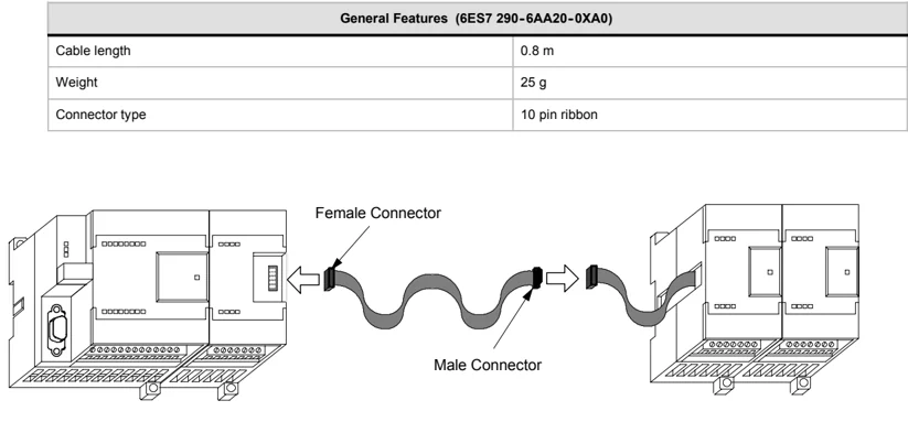
Figure A-43 Typical Installation of the I/O Expansion Cable
Tip Only one expansion cable is allowed in a CPU/expansion module chain.
466
Technical Specifications Appendix A
RS-232/PPI Multi-Master Cable and USB/PPI Multi-Master Cable
Table A-68 RS-232/PPI Multi-Master Cable and USB/PPI Multi-Master Cable Specifications
| Description Order Number | S7-200 RS-232/PPI Multi-Master Cable 6ES7 901-3CB30-0XA0 | S7-200 USB/PPI Multi-Master Cable 6ES7-901-3DB30-0XA0 |
|---|---|---|
| General Characteristics | ||
| Supply voltage | 14.4 to 28.8 VDC | 14.4 to 28.8 VDC |
| Supply current at 24 V nominal supply | 60 mA RMS max. | 50 mA RMS max. |
| Direction change delay: RS-232 stop bit edge received to RS-485 transmission disabled | - | - |
| Isolation | RS-485 to RS-232: 500 VDC | RS-485 to USB: 500 VDC |
| RS-485 Side Electrical Characteristics | ||
| Common mode voltage range | -7 V to +12 V, 1 second, 3 V RMS continuous | -7 V to +12 V, 1 second, 3 V RMS continuous |
| Receiver input impedance | 5.4 K Ω min. including termination | 5.4 K Ω min. including termination |
| Termination/bias | 10K Ω to +5 V on B, PROFIBUS pin 3 10K Ω to GND on A, PROFIBUS pin 8 | 10K Ω to +5 V on B, PROFIBUS pin 3 10K Ω to GND on A, PROFIBUS pin 8 |
| Receiver threshold/sensitivity | +/-0.2 V, 60 mV typical hysteresis | +/-0.2 V, 60 mV typical hysteresis |
| Transmitter differential output voltage | 2 V min. at RL=100 Ω, 1.5 V min. at RL=54 Ω | 2 V min. at RL=100 Ω, 1.5 V min. at RL=54 Ω |
| RS-232 Side Electrical Characteristics | ||
| Receiver input impedance | 3K Ω min. | - |
| Receiver threshold/sensitivity | 0.8 V min. low, 2.4 V max. high 0.5 V typical hysteresis | - |
| Transmitter output voltage | +/- 5 V min. at RL=3K Ω | - |
| USB Side Electrical Characteristics | ||
| Full speed (12 MB/s), Human Interface Device (HID) | ||
| Supply current at 5V | - | 50 mA max. |
| Power down current | - | 400 uA max. |
Features
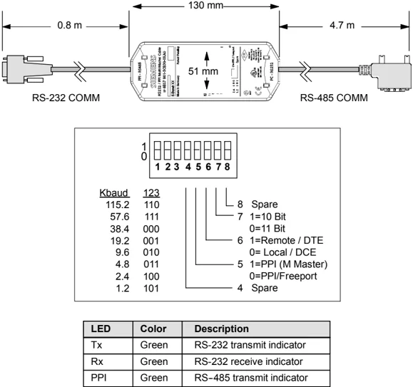
The S7-200 RS-232/PPI Multi-Master Cable comes factory set for optimal performance with the STEP 7-Micro/WIN 3.2 Service Pack 4 (or later) programming package. The factory setting for this cable is different than for the PC/PPI cables. Refer to Figure 1 to configure the cable for your application.
You can configure the S7-200 RS-232/PPI Multi-Master Cable to operate the same as the PC/PPI cable and to be compatible with any version of a STEP 7-Micro/WIN programming package by setting Switch 5 to the PPI/Freepport setting and then selecting your required baud rate.
The USB cable requires STEP 7-Micro/WIN 3.2 Service Pack 4 (or later) programming package for operation.

Tip
For more information about using these cables, refer to Chapter 7, Communicating over a Network.
467
S7-200 RS-232/PPI Multi-Master Cable
Table A-69 S7-200 RS-232/PPI Multi-Master Cable – Pin-outs for RS-485 to RS-232 Local Mode Connector
| RS-485 Connector Pin-out | RS-232 Local Connector Pin-out | ||
|---|---|---|---|
| Pin Number | Signal Description | Pin Number | Signal Description |
| 1 | No connect | 1 | Data Carrier Detect (DCD) (not used) |
| 2 | 24 V Return (RS-485 logic ground) | 2 | Receive Data (RD) (output from PC/PPI cable) |
| 3 | Signal B (RxD/TxD+) | 3 | Transmit Data (TD) (input to PC/PPI cable) |
| 4 | RTS (TTL level) | 4 | Data Terminal Ready (DTR)¹ |
| 5 | No connect | 5 | Ground (RS-232 logic ground) |
| 6 | No connect | 6 | Data Set Ready (DSR)¹ |
| 7 | 24 V Supply | 7 | Request To Send (RTS) (not used) |
| 8 | Signal A (RxD/TxD–) | 8 | Clear To Send (CTS) (not used) |
| 9 | Protocol select | 9 | Ring Indicator (RI) (not used) |
¹ Pins 4 and 6 are connected internally.
Table A-70 S7-200 RS-232/PPI Multi-Master Cable – Pin-outs for RS-485 to RS-232 Remote Mode Connector
| RS-485 Connector Pin-out | RS-232 Remote Connector Pin-out¹ | ||
|---|---|---|---|
| Pin Number | Signal Description | Pin Number | Signal Description |
| 1 | No connect | 1 | Data Carrier Detect (DCD) (not used) |
| 2 | 24 V Return (RS-485 logic ground) | 2 | Receive Data (RD) (input to PC/PPI cable) |
| 3 | Signal B (RxD/TxD+) | 3 | Transmit Data (TD) (output from PC/PPI cable) |
| 4 | RTS (TTL level) | 4 | Data Terminal Ready (DTR)² |
| 5 | No connect | 5 | Ground (RS-232 logic ground) |
| 6 | No connect | 6 | Data Set Ready (DSR)² |
| 7 | 24 V Supply | 7 | Request To Send (RTS) (output from PC/PPI cable) |
| 8 | Signal A (RxD/TxD–) | 8 | Clear To Send (CTS) (not used) |
| 9 | Protocol select | 9 | Ring Indicator (RI) (not used) |
¹ A conversion from female to male, and a conversion from 9-pin to 25-pin is required for modems.
² Pins 4 and 6 are connected internally.
Use the S7-200 RS-232/PPI Multi-Master Cable with STEP 7-Micro/WIN as a replacement for the PC/PPI cable or for Freeport operation
For connection directly to your personal computer:
- Set the PPI/Freeport mode (Switch 5=0)
- Set the baud rate (Switches 1, 2, and 3)
- Set Local (Switch 6=0). The Local setting is the same as setting the PC/PPI cable to DCE.
- Set the 11 Bit (Switch 7=0)
For connection to a modem:
- Set the PPI/Freeport mode (Switch 5=0)
- Set the baud rate (Switches 1, 2, and 3)
- Set Remote (Switch 6=1). The Remote setting is the same as setting the PC/PPI cable to DTE.
- Set the 10 Bit or 11 Bit (Switch 7) to match the number of bits per character setting of your modem.
Technical Specifications Appendix A
Use the S7-200 RS-232/PPI Multi-Master Cable with STEP 7-Micro/WIN 3.2 Service Pack 4 (or later)
For connection directly to your personal computer: ☐ Set the PPI mode (Switch 5=1) ☐ Set Local (Switch 6=0) ☐ Set 11-bit mode (Switch 7=0)
For connection to a modem: ☐ Set the PPI mode (Switch 5=1) ☐ Set Remote (Switch 6=1) ☐ Set 11-bit mode (Switch 7=0)
Tip All other switches other than those noted above do not matter when using PPI mode.
Figure A-44 shows the S7-200 RS-232/PPI Multi-Master Cable dimensions, label and LEDs.

| LED | Color | Description |
|---|---|---|
| Tx | Green | RS-232 transmit indicator |
| Rx | Green | RS-232 receive indicator |
| PPI | Green | RS-485 transmit indicator |
Figure A-44 S7-200 RS-232/PPI Multi-Master Cable Dimensions, Label and LEDs
469
S7-200 USB/PPI Multi-Master Cable
To use the USB cable, you must have STEP 7-Micro/WIN 3.2 Service Pack 4 (or later) installed. It is recommended that you use the USB cable only with an S7-200 CPU22x or later. The USB cable does not support Freeport communications or downloading the TP Designer to the TP 070.
Table A-71 S7-200 USB/PPI Multi-Master Cable - Pin-outs for the RS-485 to USB Series "A" Connector
Figure A-45 shows the S7-200 USB/PPI Multi-Master Cable dimensions and LEDs.
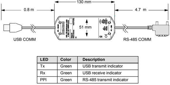
LED Color Description ---|---|--- Tx | Green | USB transmit indicator Rx | Green | USB receive indicator PPI | Green | RS-485 transmit indicator
Figure A-45 S7-200 USB/PPI Multi-Master Cable Dimensions and LEDs
Technical Specifications Appendix A
Input Simulators
| Order Number | 8 Position Simulator 6ES7 274-1XF00-0XA0 | 14 Position Simulator 6ES7 274-1XH00-0XA0 | 24 Position Simulator 6ES7 274-1XK00-0XA0 |
|---|---|---|---|
| Size (L x W x D) | 61 x 33.5 x 22 mm | 91.5 x 35.5 x 22 mm | 148.3 x 35.5 x 22 mm |
| Weight | 0.02 Kg | 0.03 Kg | 0.04 Kg |
| Points | 8 | 14 | 24 |
Figure A-46 Installation of the Input Simulator
Warning These input simulators are not approved for use in Class I DIV 2 or Class I Zone 2 hazardous locations. The switches present a potential spark hazard. Do not use input simulators in Class I DIV 2 or Class I Zone 2 hazardous locations.
471
Calculating a Power Budget
The S7-200 CPU has an internal power supply that provides power for the CPU itself, for any expansion modules, and for other 24 VDC user power requirements. Use the following information as a guide for determining how much power (or current) the S7-200 CPU can provide for your configuration.
Power Requirements
Each S7-200 CPU supplies both 5 VDC and 24 VDC power:
Each CPU has a 24 VDC sensor supply that can supply 24 VDC for local input points or for relay coils on the expansion modules. If the power requirement for 24 VDC exceeds the power budget of the CPU, you can add an external 24 VDC power supply to provide 24 VDC to the expansion modules. You must manually connect the 24 VDC supply to the input points or relay coils.
The CPU also provides 5 VDC power for the expansion modules when an expansion module is connected. If the 5 VDC power requirements for expansion modules exceeds the power budget of the CPU, you must remove expansion modules until the requirement is within the power budget.
The specifications in Appendix A provide information about the power budgets of the CPUs and the power requirements of the expansion modules.
Tip If the CPU power budget is exceeded, you may not be able to connect the maximum number of modules allowed for your CPU.
Warning Connecting an external 24 VDC power supply in parallel with the S7-200 DC Sensor Supply can result in a conflict between the two supplies as each seeks to establish its own preferred output voltage level.
The result of this conflict can be shortened lifetime or immediate failure of one or both power supplies, with consequent unpredictable operation of the PLC system. Unpredictable operation could result in death or serious injury to personnel, and/or damage to equipment.
The S7-200 DC Sensor Supply and any external power supply should provide power to different points. A single connection of the commons is allowed.

Calculating a Sample Power Requirement
Table B-1 shows a sample calculation of the power requirements for an S7-200 that includes the following:
☐ S7-200 CPU 224 AC/DC/Relay
☐ 3 each EM 223 8 DC In/8 Relay Out
☐ 1 each EM 221 8 DC In
This installation has a total of 46 inputs and 34 outputs.
Tip The CPU has already allocated the power required to drive the internal relay coils. You do not need to include the internal relay coil power requirements in a power budget calculation.
The S7-200 CPU in this example provides sufficient 5 VDC current for the expansion modules, but does not provide enough 24 VDC current from the sensor supply for all of the inputs and expansion relay coils. The I/O requires 400 mA and the S7-200 CPU provides only 280 mA. This installation requires an additional source of at least 120 mA at 24 VDC power to operate all the included 24 VDC inputs and outputs.
Table B-1 Power Budget Calculations for a Sample Configuration
Calculating a Power Budget Appendix B
Calculating Your Power Requirement
Use the table below to determine how much power (or current) the S7-200 CPU can provide for your configuration. Refer to Appendix A for the power budgets of your CPU model and the power requirements of your expansion modules.
minus
equals
Error Codes
The information about error codes is provided to help you identify problems with your S7-200 CPU.
I n This Chapter
- Fatal Error Codes and Messages . . . . . . . . . . . . . . . . . . . . . . . . . . . . . . . . . . . . . . . . . . . . . . . . . . . . . . . . . . . . . . . . . . . . . . . . . . . . . . . . . . . . . . . . . . . . . . . . . . . . . . . . . . . . . . . . . . . . . . . . . . . . . . . . . . . . . . . . . . . . . . . . . . . . . . . . . . . . . . . . . . . . . . . ........ 478
- Run-Time Programming Problems . . . . . . . . . . . . . . . . . . . . . . . . . . . . . . . . . . . . . . . . . . . . . . . . . . . . . . . . . . . . . . . . . . . . . . . . . . . . . . . . . . . . . . . . . . . . . . . . . . . . . . . . . . . . . . . ........ 479
- Compile Rule Violations . . . . . . . . . . . . . . . . . . . . . . . . . . . . . . . . . . . . . . . . . . . . . . . . . . . . . . . . . . . . . . . . . . . . . . . . . . . . . . . . . . . . . . . . . . . . . . . . . . . . . . . . . . . ........

Fatal Error Codes and Messages
Fatal errors cause the S7-200 to stop the execution of your program. Depending on the severity of the error, a fatal error can render the S7-200 incapable of performing any or all functions. The objective for handling fatal errors is to bring the S7-200 to a safe state from which the S7-200 can respond to interrogations about the existing error conditions.
The S7-200 performs the following tasks when a fatal error is detected:
- Changes to STOP mode
- Turns on both the S F/DIAG (Red) LED and the Stop LED
- Turns off the outputs
The S7-200 remains in this condition until the fatal error is corrected. To view the error codes, select the PLC > Information menu command from the main menu bar. Table C-1 provides a list with descriptions for the fatal error codes that can be read from the S7-200.
Table C-1 Fatal Error Codes and Messages Read from the S7-200
| Error Code | Description |
|---|---|
| 0000 | No fatal errors present |
| 0001 | User program checksum error |
| 0002 | Compiled ladder program checksum error |
| 0003 | Scan watchdog time-out error |
| 0004 | Permanent memory failed |
| 0005 | Permanent memory checksum error on user program |
| 0006 | Permanent memory checksum error on configuration (SDB0) parameters |
| 0007 | Permanent memory checksum error on force data |
| 0008 | Permanent memory checksum error on default output table values |
| 0009 | Permanent memory checksum error on user data, DB1 |
| 000A | Memory cartridge failed |
| 000B | Memory cartridge checksum error on user program. |
| 000C | Memory cartridge checksum error on configuration (SDB0) parameters |
| 000D | Memory cartridge checksum error on force data |
| 000E | Memory cartridge checksum error on default output table values |
| 000F | Memory cartridge checksum error on user data, DB1 |
| 0010 | Internal software error |
| 0011¹ | Compare contact indirect addressing error |
| 0012¹ | Compare contact illegal floating point value |
| 0013 | Program is not understood by this S7-200 |
| 0014¹ | Compare contact range error |
¹ The compare contact errors are the only errors that generate both fatal and non-fatal error conditions. The reason for the generation of the non-fatal error condition is to save the program address of the error.
Run-Time Programming Problems
Your program can create non-fatal error conditions (such as addressing errors) during the normal execution of the program. In this case, the S7-200 generates a non-fatal run-time error code. Table C-2 lists the descriptions of the non-fatal error codes.
Table C-2 Run-Time Programming Problems
| Error Code | Description |
|---|---|
| 0000 | No fatal errors present; no error |
| 0001 | HSC box enabled before executing HDEF box |
| 0002 | Conflicting assignment of input interrupt to a point already assigned to a HSC |
| 0003 | Conflicting assignment of inputs to an HSC already assigned to input interrupt or other HSC |
| 0004 | Attempted execution of an instruction that is not allowed in an interrupt routine |
| 0005 | Attempted execution of a second HSC/PLS with the same number before completing the first (HSC/PLS in an interrupt routine conflicts with HSC/PLS in main program) |
| 0006 | Indirect addressing error |
| 0007 | TODW (Time-of-Day Write) or TODR (Time-of-Day Read) data error |
| 0008 | Maximum user subroutine nesting level exceeded |
| 0009 | Simultaneous execution of XMT/RCV instructions on Port 0 |
| 000A | Attempt to redefine a HSC by executing another HDEF instruction for the same HSC |
| 000B | Simultaneous execution of XMT/RCV instructions on Port 1 |
| 000C | Clock cartridge not present for access by TODR, TODW, or communications |
| 000D | Attempt to redefine pulse output while it is active |
| 000E | Number of PTO profile segment was set to 0 |
| 000F | Illegal numeric value in compare contact instruction |
| 0010 | Command is not allowed in current PTO mode of operation |
| 0011 | Illegal PTO command code |
| 0012 | Illegal PTO profile table |
| 0013 | Illegal PID loop table |
| 0091 | Range error (with address information): check the operand ranges |
| 0092 | Error in count field of an instruction (with count information): verify the maximum count size |
| 0094 | Range error writing to non-volatile memory with address information |
| 009A | Attempt to switch to Freeport mode while in a user interrupt |
| 009B | Illegal index (string operation in which a starting position value of 0 is specified) |
| 009F | Memory cartridge missing or not responding |
Compile Rule Violations
When you download a program, the S7-200 compiles the program. If the S7-200 detects that the program violates a compile rule (such as an illegal instruction), the S7-200 aborts the download and generates a non-fatal, compile-rule error code. Table C-3 lists the descriptions of the error codes that are generated by violations of the compile rules.
Table C-3 Compile Rule Violations
| Error Code | Compile Errors (Non-Fatal) |
|---|---|
| 0080 | Program too large to compile; reduce program size |
| 0081 | Stack underflow; split network into multiple networks. |
| 0082 | Illegal instruction; check instruction mnemonics. |
| 0083 | Missing MEND or instruction not allowed in main program: add MEND instruction, or remove incorrect instruction. |
| 0084 | Reserved |
| 0085 | Missing FOR; add FOR instruction or delete NEXT instruction. |
| 0086 | Missing NEXT; add NEXT instruction or delete FOR instruction. |
| 0087 | Missing label (LBL, INT, SBR); add the appropriate label. |
| 0088 | Missing RET or instruction not allowed in a subroutine: add RET to the end of the subroutine or remove incorrect instruction. |
| 0089 | Missing RETI or instruction not allowed in an interrupt routine: add RETI to the end of the interrupt routine or remove incorrect instruction. |
| 008A | Reserved |
| 008B | Illegal JMP to or from an SCR segment |
| 008C | Duplicate label (LBL, INT, SBR); rename one of the labels. |
| 008D | Illegal label (LBL, INT, SBR); ensure the number of labels allowed was not exceeded. |
| 0090 | Illegal parameter; verify the allowed parameters for the instruction. |
| 0091 | Range error (with address information); check the operand ranges. |
| 0092 | Error in the count field of an instruction (with count information); verify the maximum count size. |
| 0093 | FOR/NEXT nesting level exceeded. |
| 0095 | Missing LSCR instruction (Load SCR) |
| 0096 | Missing SCRE instruction (SCR End) or disallowed instruction before the SCRE instruction |
| 0097 | User program contains both unnumbered and numbered EV/ED instructions |
| 0098 | Illegal edit in RUN mode (edit attempted on program with unnumbered EV/ED instructions) |
| 0099 | Too many hidden program segments (HIDE instructions) |
| 009B | Illegal index (string operation in which a starting position value of 0 is specified) |
| 009C | Maximum instruction length exceeded |
| 009D | Illegal parameter detected in SDB0 |
| 009E | Too many PCALL strings |
| 009F to 00FF | Reserved |
Special Memory (SM) Bits
Special memory bits provide a variety of status and control functions, and also serve as a means of communicating information between the S7-200 and your program. Special memory bits can be used as bits, bytes, words, or double words.
In This Chapter
| Description | Page |
|---|---|
| SMB0: Status Bits | 482 |
| SMB1: Status Bits | 482 |
| SMB2: Freeport Receive Character | 483 |
| SMB3: Freeport Parity Error | 483 |
| SMB4: Queue Overflow | 483 |
| SMB5: I/O Status | 484 |
| SMB6: CPU ID Register | 484 |
| SMB7: Reserved | 484 |
| SMB8 to SMB21: I/O Module ID and Error Registers | 485 |
| SMW22 to SMW26: Scan Times | 486 |
| SMB28 and SMB29: Analog Adjustment | 486 |
| SMB30 and SMB130: Freeport Control Registers | 486 |
| SMB31 and SMW32: Permanent Memory (EEPROM) Write Control | 487 |
| SMB34 and SMB35: Time Interval Registers for Timed Interrupts | 487 |
| SMB36 to SMB65: HSC0, HSC1, and HSC2 Register | 487 |
| SMB66 to SMB85: PTO/PWM Registers | 489 |
| SMB86 to SMB94, and SMB186 to SMB194: Receive Message Control | 490 |
| SMW98: Errors on the Expansion I/O Bus | 491 |
| SMB130: Freeport Control Register (see SMB30) | 491 |
| SMB131 to SMB165: HSC3, HSC4, and HSC5 Register | 491 |
| SMB166 to SMB185: PTO0, PTO1 Profile Definition Table | 492 |
| SMB186 to SMB194: Receive Message Control (see SMB86 to SMB94) | 492 |
| SMB200 to SMB549: Intelligent Module Status | 493 |

SMB0: Status Bits
As described in Table D-1, SMB0 contains eight status bits that are updated by the S7-200 at the end of each scan cycle.
Table D-1 Special Memory Byte SMB0 (SM0.0 to SM0.7)
| SM Bits | Description (Read Only) |
|---|---|
| SM0.0 | This bit is always on. |
| SM0.1 | This bit is on for the first scan cycle. One use is to call an initialization subroutine. |
| SM0.2 | This bit is turned on for one scan cycle if retentive data was lost. This bit can be used as either an error memory bit or as a mechanism to invoke a special startup sequence. |
| SM0.3 | This bit is turned on for one scan cycle when RUN mode is entered from a power-up condition. This bit can be used to provide machine warm-up time before starting an operation. |
| SM0.4 | This bit provides a clock pulse that is on for 30 seconds and off for 30 seconds, for a duty cycle time of 1 minute. It provides an easy-to-use delay, or a 1-minute clock pulse. |
| SM0.5 | This bit provides a clock pulse that is on for 0.5 seconds and then off for 0.5 seconds, for a duty cycle time of 1 second. It provides an easy-to-use delay or a 1-second clock pulse. |
| SM0.6 | This bit is a scan cycle clock which is on for one scan cycle and then off for the next scan cycle. This bit can be used as a scan counter input. |
| SM0.7 | This bit reflects the position of the Mode switch (off is TERM position, and on is RUN position). If you use this bit to enable Freeport mode when the switch is in the RUN position, normal communications with the programming device can be enabled by switching to the TERM position. |
SMB1: Status Bits
As described in Table D-2, SMB1 contains various potential error indicators. These bits are set and reset by instructions at execution time.
Table D-2 Special Memory Byte SMB1 (SM1.0 to SM1.7)
| SM Bits | Description (Read Only) |
|---|---|
| SM1.0 | This bit is turned on by the execution of certain instructions when the result of the operation is zero. |
| SM1.1 | This bit is turned on by the execution of certain instructions either when an overflow results or when an illegal numeric value is detected. |
| SM1.2 | This bit is turned on when a negative result is produced by a math operation. |
| SM1.3 | This bit is turned on when division by zero is attempted. |
| SM1.4 | This bit is turned on when the Add to Table instruction attempts to overfill the table. |
| SM1.5 | This bit is turned on when either LIFO or FIFO instructions attempt to read from an empty table. |
| SM1.6 | This bit is turned on when an attempt to convert a non-BCD value to binary is made. |
| SM1.7 | This bit is turned on when an ASCII value cannot be converted to a valid hexadecimal value. |
SMB2: Freeport Receive Character
SMB2 is the Freeport receive character buffer. As described in Table D-3, each character received while in Freeport mode is placed in this location for easy access from the ladder logic program.
Tip SMB2 and SMB3 are shared between Port 0 and Port 1. When the reception of a character on Port 0 results in the execution of the interrupt routine attached to that event (interrupt event 8), SMB2 contains the character received on Port 0, and SMB3 contains the parity status of that character. When the reception of a character on Port 1 results in the execution of the interrupt routine attached to that event (interrupt event 25), SMB2 contains the character received on Port 1 and SMB3 contains the parity status of that character.
Table D-3 Special Memory Byte SMB2
| SM Byte | Description (Read Only) |
|---|---|
| SMB2 | This byte contains each character that is received from Port 0 or Port 1 during Freeport communications. |
SMB3: Freeport Parity Error
SMB3 is used for Freeport mode and contains a parity error bit that is set when a parity error is detected on a received character. As shown in Table D-4, SM3.0 turns on when a parity error is detected. Use this bit to discard the message.
Table D-4 Special Memory Byte SMB3 (SM3.0 to SM3.7)
| SM Bits | Description (Read Only) |
|---|---|
| SM3.0 | Parity error from Port 0 or Port 1 (0 = no error; 1 = error was detected) |
| SM3.1 to SM3.7 | Reserved |
SMB4: Queue Overflow
As described in Table D-5, SMB4 contains the interrupt queue overflow bits, a status indicator showing whether interrupts are enabled or disabled, and a transmitter-idle memory bit. The queue overflow bits indicate either that interrupts are happening at a rate greater than can be processed, or that interrupts were disabled with the global interrupt disable instruction.
Table D-5 Special Memory Byte SMB4 (SM4.0 to SM4.7)
| SM Bits | Description (Read Only) |
|---|---|
| SM4.0¹ | This bit is turned on when the communications interrupt queue has overflowed. |
| SM4.1¹ | This bit is turned on when the input interrupt queue has overflowed. |
| SM4.2¹ | This bit is turned on when the timed interrupt queue has overflowed. |
| SM4.3 | This bit is turned on when a run-time programming problem is detected. |
| SM4.4 | This bit reflects the global interrupt enable state. It is turned on when interrupts are enabled. |
| SM4.5 | This bit is turned on when the transmitter is idle (Port 0). |
| SM4.6 | This bit is turned on when the transmitter is idle (Port 1). |
| SM4.7 | This bit is turned on when something is forced. |
¹ Use status bits 4.0, 4.1, and 4.2 only in an interrupt routine. These status bits are reset when the queue is emptied, and control is returned to the main program.
SMB5: I/O Status
As described in Table D-6, SMB5 contains status bits about error conditions that were detected in the I/O system. These bits provide an overview of the I/O errors detected.
Table D-6 Special Memory Byte SMB5 (SM5.0 to SM5.7)
| SM Bits | Description (Read Only) |
|---|---|
| SM5.0 | This bit is turned on if any I/O errors are present. |
| SM5.1 | This bit is turned on if too many digital I/O points have been connected to the I/O bus. |
| SM5.2 | This bit is turned on if too many analog I/O points have been connected to the I/O bus. |
| SM5.3 | This bit is turned on if too many intelligent I/O modules have been connected to the I/O bus. |
| SM5.4 to SM5.7 | Reserved. |
SMB6: CPU ID Register
As described in Table D-7, SMB6 is the identification register for the S7-200 CPU. SM6.4 to SM6.7 identify the type of S7-200 CPU. SM6.0 to SM6.3 are reserved for future use.
Table D-7 Special Memory Byte SMB6
| SM Bits | Description (Read Only) |
|---|---|
| Format | MSB 7 LSB 0 x x x x r r r r CPU ID register |
| SM6.0 to SM6.3 | Reserved |
| SM6.4 to SM6.7 | xxxx = 0000 = CPU 2220010 = CPU 224 / CPU 224XP0110 = CPU 2211001 = CPU 226 |
SMB7: Reserved
SMB7 is reserved for future use.