Changing PPI Communications to Freeport Mode
S MB30 and S MB130 configure the communications ports, 0 and 1 respectively, for Freeport operation and provide selection of baud rate, parity, and number of data bits. Figure 6-8 describes the Freeport control byte. One stop bit is generated for all configurations.
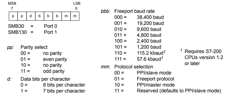
Figure 6-8 S M Control Byte for Freeport Mode (S MB30 or S MB130)
Transmitting Data
The Transmit instruction lets you send a buffer of one or more characters, up to a maximum of 255.
Figure 6-9 shows the format of the Transmit buffer.
If an interrupt routine is attached to the transmit complete event, the S7-200 generates an interrupt (interrupt event 9 for port 0 and interrupt event 26 for port 1) after the last character of the buffer is sent.
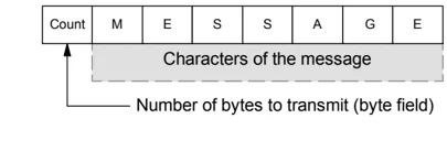
Figure 6-9 Format for the Transmit Buffer
You can make transmissions without using interrupts (for example, sending a message to a printer) by monitoring S M4.5 or S M4.6 to signal when transmission is complete.
You can use the Transmit instruction to generate a B R E A K condition by setting the number of characters to zero and then executing the Transmit instruction. This generates a B R E A K condition on the line for 16-bit times at the current baud rate. Transmitting a B R E A K is handled in the same manner as transmitting any other message, in that a Transmit interrupt is generated when the B R E A K is complete and S M4.5 or S M4.6 signals the current status of the Transmit operation.
Receiving Data
The Receive instruction lets you receive a buffer of one or more characters, up to a maximum of 255.
Figure 6-10 shows the format of the Receive buffer.
If an interrupt routine is attached to the receive message complete event, the S7-200 generates an interrupt (interrupt event 23 for port 0 and interrupt event 24 for port 1) after the last character of the buffer is received.
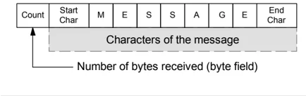
Figure 6-10 Format for the Receive Buffer
You can receive messages without using interrupts by monitoring S MB86 (port 0) or S MB186 (port 1). This byte is non-zero when the Receive instruction is inactive or has been terminated. It is zero when a receive is in progress.
As shown in Table 6-13, the Receive instruction allows you to select the message start and message end conditions, using SMB86 through SMB94 for port 0 and SMB186 through SMB194 for port 1.
Tip The receive message function is automatically terminated in case of an overrun or a parity error. You must define a start condition and an end condition (maximum character count) for the receive message function to operate.
Table 6-13 Bytes of the Receive Buffer (SMB86 to SMB94, and SMB186 to SMB194)
| Port 0 | Port 1 | Description |
|---|---|---|
| SMB86 | SMB186 | Receive message status byteMSB 7LSB 0nre00tcpn: 1 = Receive message function terminated: user issued disable command.r: 1 = Receive message function terminated: error in input parameters or missing start or end condition.e: 1 = End character received.t: 1 = Receive message function terminated: timer expired.c: 1 = Receive message function terminated: maximum character count achieved.p 1 = Receive message function terminated: a parity error. |
| SMB87 | SMB187 | Receive message control byteMSB 7LSB 0enscecilc/mtmrbk0en: 0 = Receive message function is disabled.1 = Receive message function is enabled.The enable/disable receive message bit is checked each time the RCV instruction is executed.sc: 0 = Ignore SMB88 or SMB188.1 = Use the value of SMB88 or SMB188 to detect start of message.ec: 0 = Ignore SMB89 or SMB189.1 = Use the value of SMB89 or SMB189 to detect end of message.il: 0 = Ignore SMW90 or SMW190.1 = Use the value of SMW90 or SMW190 to detect an idle line condition.c/m: 0 = Timer is an inter-character timer.1 = Timer is a message timer.tmr: 0 = Ignore SMW92 or SMW192.1 = Terminate receive if the time period in SMW92 or SMW192 is exceeded.bk: 0 = Ignore break conditions.1 = Use break condition as start of message detection. |
| SMB88 | SMB188 | Start of message character. |
| SMB89 | SMB189 | End of message character. |
| SMW90 | SMW190 | Idle line time period given in milliseconds. The first character received after idle line time has expired is the start of a new message. |
| SMW92 | SMW192 | Inter-character/message timer time-out value given in milliseconds. If the time period is exceeded, the receive message function is terminated. |
| SMB94 | SMB194 | Maximum number of characters to be received (1 to 255 bytes). This range must be set to the expected maximum buffer size, even if the character count message termination is not used. |
88
S7-200 Instruction Set Chapter 6
Start and End Conditions for the Receive Instruction
The Receive instruction uses the bits of the receive message control byte (SMB87 or SMB187) to define the message start and end conditions.
Tip
If there is traffic present on the communications port from other devices when the Receive instruction is executed, the receive message function could begin receiving a character in the middle of that character, resulting in a possible parity error and termination of the receive message function. If parity is not enabled the received message could contain incorrect characters. This situation can occur when the start condition is specified to be a specific start character or any character, as described in item 2. and item 6. below.
The Receive instruction supports several message start conditions. Specifying a start condition involving a break or an idle line detection avoids this problem by forcing the receive message function to synchronize the start of the message with the start of a character before placing characters into the message buffer.
The Receive instruction supports several start conditions:
- Idle line detection: The idle line condition is defined as a quiet or idle time on the transmission line. A receive is started when the communications line has been quiet or idle for the number of milliseconds specified in SMW90 or SMW190. When the Receive instruction in your program is executed, the receive message function initiates a search for an idle line condition. If any characters are received before the idle line time expires, the receive message function ignores those characters and restarts the idle line timer with the time from SMW90 or SMW190. See Figure 6-11. After the idle line time expires, the receive message function stores all subsequent characters received in the message buffer.
The idle line time should always be greater than the time to transmit one character (start bit, data bits, parity and stop bits) at the specified baud rate. A typical value for the idle line time is three character times at the specified baud rate.
You use idle line detection as a start condition for binary protocols, protocols where there is not a particular start character, or when the protocol specifies a minimum time between messages.
Setup: il = 1, sc = 0, bk = 0, SMW90/SMW190 = idle line timeout in milliseconds
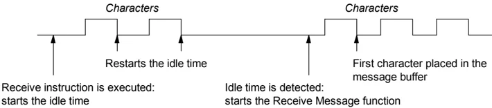
Figure 6-11 Using Idle Time Detection to Start the Receive Instruction
- Start character detection: The start character is any character which is used as the first character of a message. A message is started when the start character specified in SMB88 or SMB188 is received. The receive message function stores the start character in the receive buffer as the first character of the message. The receive message function ignores any characters that are received before the start character. The start character and all characters received after the start character are stored in the message buffer.
Typically, you use start character detection for ASCII protocols in which all messages start with the same character.
Setup: il = 0, sc = 1, bk = 0, SMW90/SMW190 = don't care, SMB88/SMB188 = start character
89
- Idle line and start character: The Receive instruction can start a message with the combination of an idle line and a start character. When the Receive instruction is executed, the receive message function searches for an idle line condition. After finding the idle line condition, the receive message function looks for the specified start character. If any character but the start character is received, the receive message function restarts the search for an idle line condition. All characters received before the idle line condition has been satisfied and before the start character has been received are ignored. The start character is placed in the message buffer along with all subsequent characters.
The idle line time should always be greater than the time to transmit one character (start bit, data bits, parity and stop bits) at the specified baud rate. A typical value for the idle line time is three character times at the specified baud rate.
Typically, you use this type of
The Receive instruction supports several ways to terminate a message. The message can be terminated on one or a combination of the following:
- End character detection: The end character is any character which is used to denote the end of the message. After finding the start condition, the Receive instruction checks each character received to see if it matches the end character. When the end character is received, it is placed in the message buffer and the receive is terminated.
Typically, you use end character detection with ASCII protocols where every message ends with a specific character. You can use end character detection in combination with the intercharacter timer, the message timer or the maximum character count to terminate a message.
Setup: ec = 1, SMB89/SMB189 = end character
- Intercharacter timer: The intercharacter time is the time measured from the end of one character (the stop bit) to the end of the next character (the stop bit). If the time between characters (including the second character) exceeds the number of milliseconds specified in SMW92 or SMW192, the receive message function is terminated. The intercharacter timer is restarted on each character received. See Figure 6-12.
You can use the intercharacter timer to terminate a message for protocols which do not have a specific end-of-message character. This timer must be set to a value greater than one character time at the selected baud rate since this timer always includes the time to receive one entire character (start bit, data bits, parity and stop bits).
You can use the intercharacter timer in combination with the end character detection and the maximum character count to terminate a message.
Setup: c/m = 0, tmr = 1, SMW92/SMW192 = timeout in milliseconds

Figure 6-12 Using the Intercharacter Timer to Terminate the Receive Instruction
- Message timer: The message timer terminates a message at a specified time after the start of the message. The message timer starts as soon as the start condition(s) for the receive message function have been met. The message timer expires when the number of milliseconds specified in SMW92 or SMW192 have passed. See Figure 6-13.
Typically, you use a message timer when the communications devices cannot guarantee that there will not be time gaps between characters or when operating over modems. For modems, you can use a message timer to specify a maximum time allowed to receive the message after the message has started. A typical value for a message timer would be about 1.5 times the time required to receive the longest possible message at the selected baud rate.
You can use the message timer in combination with the end character detection and the maximum character count to terminate a message.
Setup: c/m = 1, tmr = 1, SMW92/SMW192 = timeout in milliseconds

Figure 6-13 Using the Message Timer to Terminate the Receive Instruction
- Maximum character count: The Receive instruction must be told the maximum number of characters to receive (SMB94 or SMB194). When this value is met or exceeded, the receive message function is terminated. The Receive instruction requires that the user specify a maximum character count even if this is not specifically used as a terminating condition. This is because the Receive instruction needs to know the maximum size of the receive message so that user data placed after the message buffer is not overwritten.
The maximum character count can be used to terminate messages for protocols where the message length is known and always the same. The maximum character count is always used in combination with the end character detection, intercharacter timer, or message timer.
-
Parity errors: The Receive instruction is automatically terminated when the hardware signals a parity error on a received character. Parity errors are only possible if parity is enabled in SMB30 or SMB130. There is no way to disable this function.
-
User termination: The user program can terminate a receive message function by executing another Receive instruction with the enable bit (EN) in SMB87 or SMB187 set to zero. This immediately terminates the receive message function.
Using Character Interrupt Control to Receive Data
To allow complete flexibility in protocol support, you can also receive data using character interrupt control. Each character received generates an interrupt. The received character is placed in SMB2, and the parity status (if enabled) is placed in SM3.0 just prior to execution of the interrupt routine attached to the receive character event. SMB2 is the Freeport receive character buffer. Each character received while in Freeport mode is placed in this location for easy access from the user program. SMB3 is used for Freeport mode and contains a parity error bit that is turned on when a parity error is detected on a received character. All other bits of the byte are reserved. Use the parity bit either to discard the message or to generate a negative acknowledgement to the message.
When the character interrupt is used at high baud rates (38.4 kbaud to 115.2 kbaud), the time between interrupts is very short. For example, the character interrupt for 38.4 kbaud is 260 microseconds, for 57.6 kbaud is 173 microseconds, and for 115.2 kbaud is 86 microseconds. Ensure that you keep the interrupt routines very short to avoid missing characters, or else use the Receive instruction.
Tip
SMB2 and SMB3 are shared between Port 0 and Port 1. When the reception of a character on Port 0 results in the execution of the interrupt routine attached to that event (interrupt event 8), SMB2 contains the character received on Port 0, and SMB3 contains the parity status of that character. When the reception of a character on Port 1 results in the execution of the interrupt routine attached to that event (interrupt event 25), SMB2 contains the character received on Port 1 and SMB3 contains the parity status of that character.
92
S7-200 Instruction Set Chapter 6
Example: Transmit and Receive Instructions
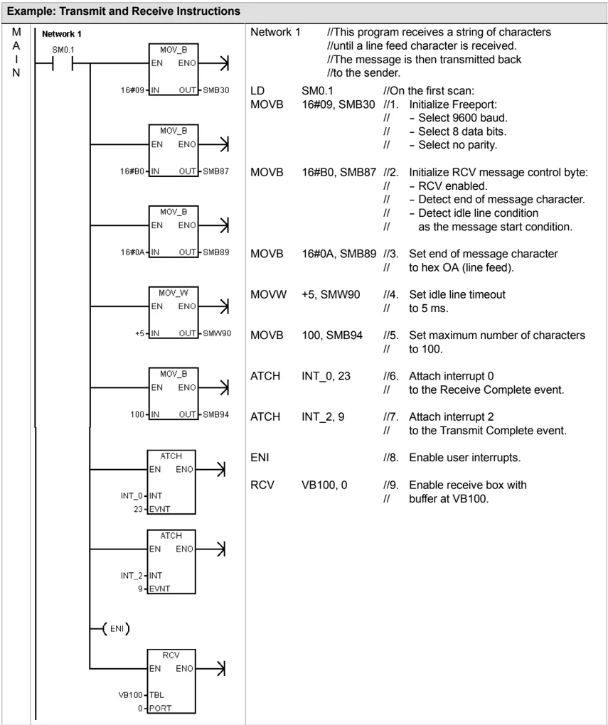
93
Example: Transmit and Receive Instructions, continued
| INT 0 | Network 1 SMB86 ==B 16#20 MOV_B EN ENO 10 IN OUT SMB34 ATCH EN ENO INT_1 INT 10 EVNT (RET) NOT RCV EN ENO VB100 TBL 0 PORT | Network 1 //Receive complete interrupt routine: //1. If receive status shows receive of // end character, then attach a // 10 ms timer to trigger a transmit and return. //2. If the receive completed for any other reason, // then start a new receive. LDB= SMB86, 16#20 MOVB 10, SMB34 ATCH INT_1, 10 CRETI NOT RCV VB100, 0 |
|---|---|---|
| INT 1 | Network 1 SM0.0 DTCH EN ENO 10 EVNT XMT EN ENO VB100 TBL 0 PORT | Network 1 //10-ms Timer interrupt: //1. Detach timer interrupt. //2. Transmit message back to user on port. LD SM0.0 DTCH 10 XMT VB100, 0 |
| INT 2 | Network 1 SM0.0 RCV EN ENO VB100 TBL 0 PORT | Network 1 //Transmit Complete interrupt: //Enable another receive. LD SM0.0 RCV VB100, 0 |
94
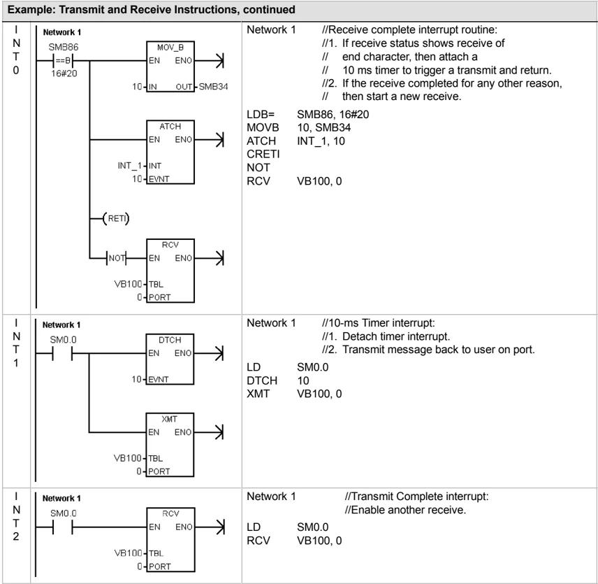
Get Port Address and Set Port Address Instructions
The Get Port Address instruction (GPA) reads the station address of the S7-200 CPU port specified in PORT and places the value in the address specified in ADDR.
The Set Port Address instruction (SPA) sets the port station address (PORT) to the value specified in ADDR. The new address is not saved permanently. After a power cycle, the affected port returns to the last address (the one that was downloaded with the system block).
Error conditions that set ENO = 0: ■ 0006 (indirect address) ■ 0004 (attempted to perform a Set Port Address instruction in an interrupt routine)
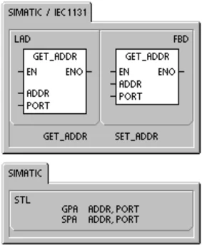
Table 6-14 Valid Operands for the Get Port Address and Set Port Address Instructions
Compare Instructions
Comparing Numerical Values
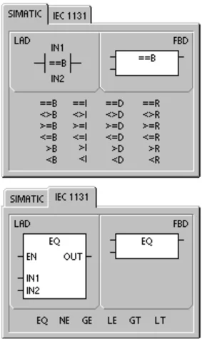
The compare instructions are used to compare two values:
IN1 = IN2 \quad IN1 >= IN2 \quad IN1 <= IN2 IN1 > IN2 \quad IN1 < IN2 \quad IN1 <> IN2
Compare Byte operations are unsigned. Compare Integer operations are signed. Compare Double Word operations are signed. Compare Real operations are signed.
For LAD and FBD: When the comparison is true, the Compare instruction turns on the contact (LAD) or output (FBD).
For STL: When the comparison is true, the Compare instruction Loads, ANDs, or ORs a 1 with the value on the top of the stack (STL).
When you use the IEC compare instructions, you can use various data types for the inputs. However, both input values must be of the same data type.
Notice
The following conditions are fatal errors and cause your S7-200 to immediately stop the execution of your program:
- Illegal indirect address is encountered (any Compare instruction)
- Illegal real number (for example, NAN) is encountered (Compare Real instruction)
To prevent these conditions from occurring, ensure that you properly initialize pointers and values that contain real numbers before executing compare instructions that use these values.
Compare instructions are executed regardless of the state of power flow.
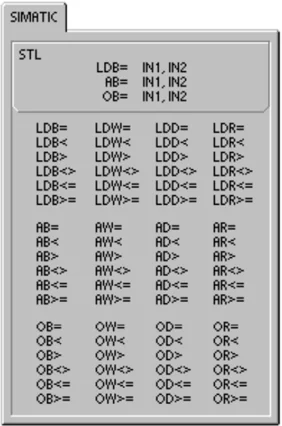
Table 6-15 Valid Operands for the Compare Instructions \begin{tabular}{|l|l|l|} \hline Inputs/Outputs & Type & Operands \ \hline IN1, IN2 & BYTE & IB, QB, VB, MB, SMB, SB, LB, AC, *VD, *LD, *AC, Constant \ \cline{2-3} & INT & IW, QW, VW, MW, SMW, SW, T, C, LW, AC, AIW, *VD, *LD, *AC, Constant \ \cline{2-3} & DINT & ID, QD, VD, MD, SMD, SD, LD, AC, HC, *VD, *LD, *AC, Constant \ \cline{2-3} & REAL & ID, QD, VD, MD, SMD, SD, LD, AC, *VD, *LD, *AC, Constant \ \hline Output (or OUT) & BOOL & I, Q, V, M, SM, S, T, C, L, Power Flow \ \hline \end{tabular}
S7-200 Instruction Set Chapter 6
Example: Compare Instructions
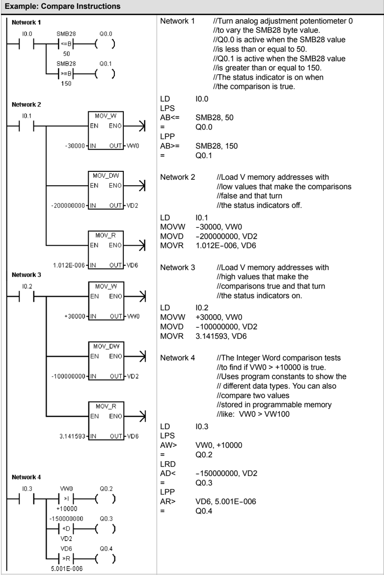
Network 1 //Turn analog adjustment potentiometer 0 //to vary the SMB28 byte value. //Q0.0 is active when the SMB28 value //is less than or equal to 50. //Q0.1 is active when the SMB28 value //is greater than or equal to 150. //The status indicator is on when //the comparison is true.
LD I0.0 LPS AB<= SMB28, 50 = Q0.0 LPP AB>= SMB28, 150 = Q0.1
Network 2 //Load V memory addresses with //low values that make the comparisons //false and that turn //the status indicators off.
LD I0.1 MOVW -30000, VW0 MOVD -200000000, VD2 MOVR 1.012E-006, VD6
Network 3 //Load V memory addresses with //high values that make the //comparisons true and that turn //the status indicators on.
LD I0.2 MOVW +30000, VW0 MOVD -100000000, VD2 MOVR 3.141593, VD6
Network 4 //The Integer Word comparison tests //to find if VW0 > +10000 is true. //Uses program constants to show the //different data types. You can also //compare two values //stored in programmable memory //like: VW0 > VW100
LD I0.3 LPS AW> VW0, +10000 = Q0.2 LRD AD< -150000000, VD2 = Q0.3 LPP AR> VD6, 5.001E-006 = Q0.4
97
Compare String
The Compare String instruction compares two strings of ASCII characters:
IN1 = IN2 \quad IN1 <> IN2
When the comparison is true, the Compare instruction turns the contact (LAD) or output (FBD) on, or the compare instruction Loads, ANDs or ORs a 1 with the value on the top of the stack (STL).
Notice
The following conditions are fatal errors and cause your S7-200 to immediately stop the execution of your program:
■ Illegal indirect address is encountered (any compare instruction)
A string with a length greater than 254 characters is encountered (Compare String instruction)
A string whose starting address and length are such that it will not fit in the specified memory area (Compare String instruction)
To prevent these conditions from occurring, ensure that you properly initialize pointers and memory locations that are intended to hold ASCII strings prior to executing compare instructions that use these values. Ensure that the buffer reserved for an ASCII string can reside completely within the specified memory area.
Compare instructions are executed regardless of the state of power flow.
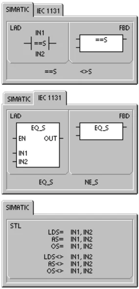
Table 6-16 Valid Operands for the Compare String Instructions \begin{tabular}{|l|l|l|} \hline Inputs/Outputs & Type & Operands \ \hline IN1 & STRING & VB, LB, *VD, *LD, *AC, constant \ \hline IN2 & STRING & VB, LB, *VD, *LD, *AC \ \hline Output (OUT) & BOOL & I, Q, V, M, SM, S, T, C, L, Power Flow \ \hline \end{tabular}
Conversion Instructions
Standard Conversion Instructions
Numerical Conversions
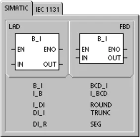
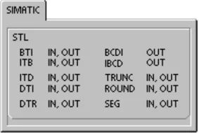
The Byte to Integer (BTI), Integer to Byte (ITB), Integer to Double Integer (ITD), Double Integer to Integer (DTI), Double Integer to Real (DTR), BCD to Integer (BCDI) and Integer to BCD (IBCD) instructions convert an input value IN to the specified format and stores the output value in the memory location specified by OUT. For example, you can convert a double integer value to a real number. You can also convert between integer and BCD formats.
Round and Truncate
The Round instruction (ROUND) converts a real value IN to a double integer value and places the rounded result into the variable specified by OUT.
The Truncate instruction (TRUNC) converts a real number IN into a double integer and places the whole-number portion of the result into the variable specified by OUT.
Segment
The Segment instruction (SEG) allows you to generate a bit pattern that illuminates the segments of a seven-segment display.
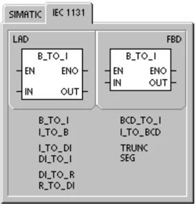
Table 6-17 Valid Operands for the Standard Conversion Instructions \begin{tabular}{|l|l|l|} \hline Inputs/Outputs & Data Type & Operands \ \hline IN & BYTE & IB, QB, VB, MB, SMB, SB, LB, AC, *VD, *LD, *AC, Constant \ \cline{2-3} & WORD, INT & IW, QW, VW, MW, SMW, SW, T, C, LW, AIW, AC, *VD, *LD, *AC, Constant \ \cline{2-3} & DINT & ID, QD, VD, MD, SMD, SD, LD, HC, AC, *VD, *LD, *AC, Constant \ \cline{2-3} & REAL & ID, QD, VD, MD, SMD, SD, LD, AC, *VD, *LD, *AC, Constant \ \hline OUT & BYTE & IB, QB, VB, MB, SMB, SB, LB, AC, *VD, *LD, *AC \ \cline{2-3} & WORD, INT & IW, QW, VW, MW, SMW, SW, T, C, LW, AC, *VD, *LD, *AC \ \cline{2-3} & DINT, REAL & ID, QD, VD, MD, SMD, SD, LD, AC, *VD, *LD, *AC \ \hline \end{tabular}
Operation of the BCD to Integer and Integer to BCD Instructions
The BCD to Integer instruction (BCDI) converts the binary-coded decimal value IN to an integer value and loads the result into the variable specified by OUT. The valid range for IN is 0 to 9999 BCD.
The Integer to BCD instruction (IBCD) converts the input integer value IN to a binary-coded decimal and loads the result into the variable specified by OUT. The valid range for IN is 0 to 9999 integer.
Error conditions that set ENO = 0
- SM1.6 (invalid BCD)
- 0006 (indirect address)
SM bits affected:
- SM1.6 (invalid BCD)
Operation of the Double Integer to Real Instruction
The Double Integer to Real instruction (DTR) converts a 32-bit, signed integer IN into a 32-bit real number and places the result into the variable specified by OUT.
Error conditions that set ENO = 0
- 0006 (indirect address)
Operation of the Double Integer to Integer Instruction
The Double Integer to Integer instruction (DTI) converts the double integer value IN to an integer value and places the result into the variable specified by OUT.
If the value that you are converting is too large to be represented in the output, then the overflow bit is set and the output is not affected.
Error conditions that set ENO = 0
- SM1.1 (overflow)
- 0006 (indirect address)
SM bits affected:
- SM1.1 (overflow)
Operation of the Integer to Double Integer Instruction
The Integer to Double Integer instruction (ITD) converts the integer value IN to a double integer value and places the result into the variable specified by OUT. The sign is extended.
Error conditions that set ENO = 0
- 0006 (indirect address)
Operation of the Byte to Integer Instruction
The Byte to Integer instruction (BTI) converts the byte value IN to an integer value and places the result into the variable specified by OUT. The byte is unsigned, therefore there is no sign extension.
Error conditions that set ENO = 0
- 0006 (indirect address)
Operation of the Integer to Byte Instruction
The Integer to Byte instruction (ITB) converts the word value IN to a byte value and places the result into the variable specified by OUT. Values 0 to 255 are converted. All other values result in overflow and the output is not affected.
Error conditions that set ENO = 0
- SM1.1 (overflow)
- 0006 (indirect address)
SM bits affected:
- SM1.1 (overflow)
Tip To change an integer to a real number, use the Integer to Double Integer instruction and then use the Double Integer to Real instruction.
100
Operation of the Round and Truncate Instructions
The Round instruction (ROUND) converts the real-number value IN to a double integer value and places the result into the variable specified by OUT. If the fraction portion is 0.5 or greater, the number is rounded up.
The Truncate instruction (TRUNC) converts a real-number value IN into a double integer and places the result into the variable specified by OUT. Only the whole number portion of the real number is converted, and the fraction is discarded.
If the value that you are converting is not a valid real number or is too large to be represented in the output, then the overflow bit is set and the output is not affected.
Error conditions that set ENO = 0
- SM1.1 (overflow)
- 0006 (indirect address)
SM bits affected:
- SM1.1 (overflow)
Example: Standard Conversion Instructions
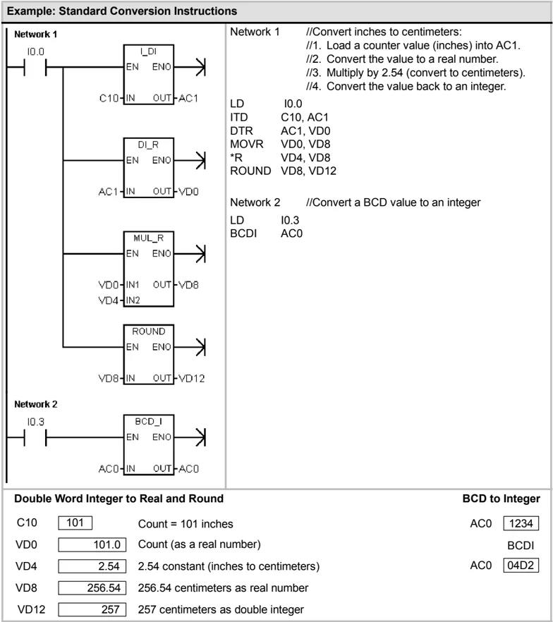
| Double Word Integer to Real and Round | BCD to Integer |
|---|---|
C10 101 Count = 101 inches |
AC0 1234 |
VD0 101.0 Count (as a real number) |
BCDI |
VD4 2.54 2.54 constant (inches to centimeters) |
AC0 04D2 |
VD8 256.54 256.54 centimeters as real number |
|
VD12 257 257 centimeters as double integer |
Operation of the Segment Instruction
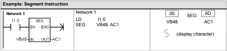
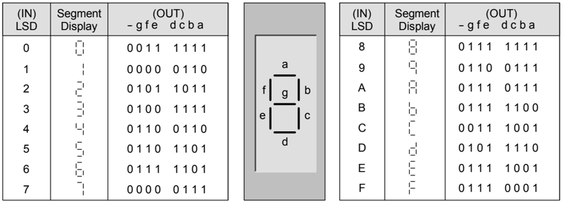
To illuminate the segments of a seven-segment display, the Segment instruction (SEG) converts the character (byte) specified by IN to generate a bit pattern (byte) at the location specified by OUT.
The illuminated segments represent the character in the least significant digit of the input byte. Figure 6-14 shows the seven-segment display coding used by the Segment instruction.
Error conditions that set ENO = 0 ■ 0006 (indirect address)
\begin{tabular}{|c|c|c|c|c|c|} \hline \multicolumn{1}{|c|}{(IN)} & \multicolumn{1}{c|}{Segment} & \multicolumn{1}{c|}{(OUT)} & \multicolumn{1}{c|}{(IN)} & \multicolumn{1}{c|}{Segment} & \multicolumn{1}{c|}{(OUT)} \ \cline{1-2}\cline{3-3}\cline{4-5}\cline{6-6} LSD & Display & - g f e d c b a & LSD & Display & - g f e d c b a \ \hline 0 & \square & 0 0 1 1 1 1 1 1 & 8 & 8 & 0 1 1 1 1 1 1 1 \ \hline 1 & $|$ & 0 0 0 0 0 1 1 0 & 9 & 9 & 0 1 1 0 0 1 1 1 \ \hline 2 & 2 & 0 1 0 1 1 0 1 1 & A & A & 0 1 1 1 0 1 1 1 \ \hline 3 & 3 & 0 1 0 0 1 1 1 1 & B & b & 0 1 1 1 1 1 0 0 \ \hline 4 & 4 & 0 1 1 0 0 1 1 0 & C & C & 0 0 1 1 1 0 0 1 \ \hline 5 & 5 & 0 1 1 0 1 1 0 1 & D & d & 0 1 0 1 1 1 1 0 \ \hline 6 & 6 & 0 1 1 1 1 1 0 1 & E & E & 0 1 1 1 1 0 0 1 \ \hline 7 & 7 & 0 0 0 0 0 1 1 1 & F & F & 0 1 1 1 0 0 0 1 \ \hline \end{tabular}
Figure 6-14 Coding for a Seven-Segment Display
Example: Segment Instruction
ASCII Conversion Instructions
Valid ASCII characters are the hexadecimal values 30 to 39, and 41 to 46.
Converting between ASCII and Hexadecimal Values
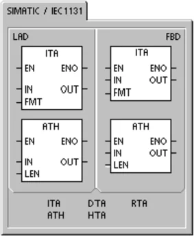
The ASCII to Hexadecimal instruction (ATH) converts a number LEN of ASCII characters, starting at IN, to hexadecimal digits starting at OUT. The Hexadecimal to ASCII instruction (HTA) converts the hexadecimal digits, starting with the input byte IN, to ASCII characters starting at OUT. The number of hexadecimal digits to be converted is specified by length LEN.
The maximum number of ASCII characters or hexadecimal digits that can be converted is 255. Valid ASCII input
Valid ASCII input characters are alphanumeric characters 0 to 9 with a hex code value of 30 to 39, and uppercase characters A to F with a hex code value of 41 to 46.
Error conditions that set ENO = 0
- SM1.7 (illegal ASCII) ASCII to Hexadecimal only
- 0006 (indirect address)
- 0091 (operand out of range)
SM bits affected:
- SM1.7 (illegal ASCII)
Converting Numerical Values to ASCII
The Integer to ASCII (ITA), Double Integer to ASCII (DTA), and Real to ASCII (RTA) instructions convert integer, double integer, or real number values to ASCII characters.
Table 6-18 Valid Operands for the ASCII Conversion Instructions \begin{tabular}{|l|l|l|} \hline Inputs/Outputs & Data Type & Operands \ \hline IN & BYTE & IB, QB, VB, MB, SMB, SB, LB, *VD, *LD, *AC \ & INT & IW, QW, VW, MW, SMW, SW, T, C, LW, AC, AIW, *VD, *LD, *AC, Constant \ & DINT & ID, QD, VD, MD, SMD, SD, LD, AC, HC, *VD, *LD, *AC, Constant \ & REAL & ID, QD, VD, MD, SMD, SD, LD, AC, *VD, *LD, *AC, Constant \ \hline LEN, FMT & BYTE & IB, QB, VB, MB, SMB, SB, LB, AC, *VD, *LD, *AC, Constant \ \hline OUT & BYTE & IB, QB, VB, MB, SMB, SB, LB, *VD, *LD, *AC \ \hline \end{tabular}
Operation of the Integer to ASCII Instruction
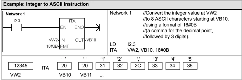
The Integer to ASCII instruction (ITA) converts an integer word IN to an array of ASCII characters. The format FMT specifies the conversion precision to the right of the decimal, and whether the decimal point is to be shown as a comma or a period. The resulting conversion is placed in 8 consecutive bytes beginning with OUT.
The array of ASCII characters is always 8 characters.
Error conditions that set ENO = 0
- 0006 (indirect address)
- Illegal format
- nnn > 5
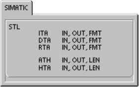
Figure 6-15 describes the format operand for the Integer to ASCII instruction. The size of the output buffer is always 8 bytes. The number of digits to the right of the decimal point in the output buffer is specified by the nnn field. The valid range of the nnn field is 0 to 5. Specifying 0 digits to the right of the decimal point causes the value to be displayed without a decimal point. For values of nnn bigger than 5, the output buffer is filled with ASCII spaces. The c bit specifies the use of either a comma (c=1) or a decimal point (c=0) as the separator between the whole number and the fraction. The upper 4 bits must be zero.
Figure 6-15 shows examples of values that are formatted using a decimal point (c=0) with three digits to the right of the decimal point (nnn=011). The output buffer is formatted according to the following rules:
- Positive values are written to the output buffer without a sign.
- Negative values are written to the output buffer with a leading minus sign (-).
- Leading zeros to the left of the decimal point (except the digit adjacent to the decimal point) are suppressed.
- Values are right-justified in the output buffer.
FMT
MSB 7 6 5 4 3 2 1 0 LSB 0 0 0 0 c n n n
c = comma (1) or decimal point (0) nnn = digits to right of decimal point
in=□□ in=-123 in=□□□□ in = -12345
| Out | Out +1 | Out +2 | Out +3 | Out +4 | Out +5 | Out +6 | Out +7 |
|---|---|---|---|---|---|---|---|
| 0 | . | 0 | 1 | 2 | |||
| - | 0 | . | 1 | 2 | 3 | ||
| 1 | . | 2 | 3 | 4 | |||
| - | 1 | 2 | . | 3 | 4 | 5 |
Figure 6-15 FMT Operand for the Integer to ASCII (ITA) Instruction
Operation of the Double Integer to ASCII Instruction
The Double Integer to ASCII (DTA) instruction converts a double word IN to an array of ASCII characters. The format operand FMT specifies the conversion precision to the right of the decimal. The resulting conversion is placed in 12 consecutive bytes beginning with OUT.
The size of the output buffer is always 12 bytes.
Figure 6-16 describes the format operand for the Double Integer to ASCII instruction. The number of digits to the right of the decimal point in the output buffer is specified by the nnn field. The valid range of the nnn field is 0 to 5. Specifying 0 digits to the right of the decimal point causes the value to be displayed without a decimal point. For values of nnn bigger than 5, the output buffer is filled with ASCII spaces. The c bit specifies the use of either a comma (c=1) or a decimal point (c=0) as the separator between the whole number and the fraction. The upper 4 bits must be zero.
Figure 6-16 shows examples of values that are formatted using a decimal point (c=0) with four digits to the right of the decimal point (nnn=100). The output buffer is formatted according to the following rules:
- Positive values are written to the output buffer without a sign.
- Negative values are written to the output buffer with a leading minus sign (-).
- Leading zeros to the left of the decimal point (except the digit adjacent to the decimal point) are suppressed.
- Values are right-justified in the output buffer.
Error conditions that set ENO = 0
- 0006 (indirect address)
- Illegal format
- nnn > 5
104

S7-200 Instruction Set Chapter 6

Figure 6-16 FMT Operand for the Double Integer to ASCII (DTA) Instruction
Operation of the Real to ASCII Instruction
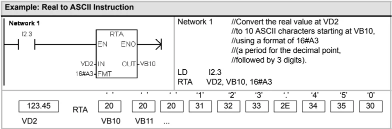
The Real to ASCII instruction (RTA) converts a real-number value IN to ASCII characters. The format FMT specifies the conversion precision to the right of the decimal, whether the decimal point is shown as a comma or a period, and the output buffer size.
The resulting conversion is placed in an output buffer beginning with OUT.
The number (or length) of the resulting ASCII characters is the size of the output buffer and can be specified to a size ranging from 3 to 15 bytes or characters.
The real-number format used by the S7-200 supports a maximum of 7 significant digits. Attempting to display more than 7 significant digits produces a rounding error.
Figure 6-17 describes the format operand (FMT) for the RTA instruction. The size of the output buffer is specified by the ssss field. A size of 0, 1, or 2 bytes is not valid. The number of digits to the right of the decimal point in the output buffer is specified by the nnn field. The valid range of the nnn field is 0 to 5. Specifying 0 digits to the right of the decimal point causes the value to be displayed without a decimal point. The output buffer is filled with ASCII spaces for values of nnn bigger than 5 or when the specified output buffer is too small to store the converted value. The c bit specifies the use of either a comma (c=1) or a decimal point (c=0) as the separator between the whole number and the fraction.
Figure 6-17 also shows examples of values that are formatted using a decimal point (c=0) with one digit to the right of the decimal point (nnn=001) and a buffer size of six bytes (ssss=0110). The output buffer is formatted according to the following rules:
- Positive values are written to the output buffer without a sign.
- Negative values are written to the output buffer with a leading minus sign (-).
- Leading zeros to the left of the decimal point (except the digit adjacent to the decimal point) are suppressed.
- Values to the right of the decimal point are rounded to fit in the specified number of digits to the right of the decimal point.
- The size of the output buffer must be a minimum of three bytes more than the number of digits to the right of the decimal point.
- Values are right-justified in the output buffer.
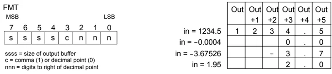
Figure 6-17 FMT Operand for the Real to ASCII (RTA) Instruction
Error conditions that set ENO = 0
- 0006 (indirect address)
- nnn > 5
- ssss < 3
- ssss < number of characters in OUT
105
S7-200 Programmable Controller System Manual
Example: ASCII to Hexadecimal Instruction
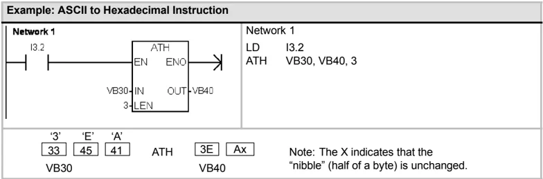
Note: The X indicates that the "nibble" (half of a byte) is unchanged.
Example: Integer to ASCII Instruction
Example: Real to ASCII Instruction
106
String Conversion Instructions
Converting Numerical Values to String
The Integer to String (ITS), Double Integer to String (DTS), and Real to String (RTS) instructions convert integers, double integers, or real number values (IN) to an ASCII string (OUT).
Operation of the Integer to String
The Integer to String instruction (ITS) converts an integer word IN to an ASCII string with a length of 8 characters. The format (FMT) specifies the conversion precision to the right of the decimal, and whether the decimal point is to be shown as a comma or a period. The resulting string is written to 9 consecutive bytes starting at OUT. See the section, format for strings in Chapter 4 for more information.
Error conditions that set ENO = 0
- 0006 (indirect address)
- 0091 (operand out of range)
- Illegal format (nnn > 5)
Figure 6-18 describes the format operand for the Integer to String instruction. The length of the output string is always 8 characters. The number of digits to the right of the decimal point in the output buffer is specified by the nnn field. The valid range of the nnn field is 0 to 5. Specifying 0 digits to the right of the decimal point causes the value to be displayed without a decimal point. For values of nnn greater than 5, the output is a string of 8 ASCII space characters. The c bit specifies the use of either a comma (c=1) or a decimal point (c=0) as the separator between the whole number and the fraction. The upper 4 bits of the format must be zero.
Figure 6-18 also shows examples of values that are formatted using a decimal point (c= 0) with three digits to the right of the decimal point (nnn = 011). The value at OUT is the length of the string.
The output string is formatted according to the following rules:
- Positive values are written to the output buffer without a sign.
- Negative values are written to the output buffer with a leading minus sign (-).
- Leading zeros to the left of the decimal point (except the digit adjacent to the decimal point) are suppressed.
- Values are right-justified in the output string.
Table 6-19 Valid Operands for the Instructions That Convert Numerical Values to Strings
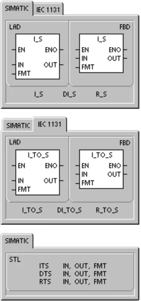

Figure 6-18 FMT Operand for the Integer to String Instruction
Operation of the Double Integer to String
The Double Integer to String instruction (DTS) converts a double integer IN to an ASCII string with a length of 12 characters. The format (FMT) specifies the conversion precision to the right of the decimal, and whether the decimal point is to be shown as a comma or a period. The resulting string is written to 13 consecutive bytes starting at OUT. For more information, see the section that describes the format for strings in Chapter 4.
Figure 6-19 describes the format operand for the Integer to String instruction. The length of the output string is always 8 characters. The number of digits to the right of the decimal point in the output buffer is specified by the nnn field. The valid range of the nnn field is 0 to 5. Specifying 0 digits to the right of the decimal point causes the value to be displayed without a decimal point. For values of nnn greater than 5, the output is a string of 12 ASCII space characters. The c bit specifies the use of either a comma (c=1) or a decimal point (c=0) as the separator between the whole number and the fraction. The upper 4 bits of the format must be zero.
Figure 6-19 also shows examples of values that are formatted using a decimal point (c=0) with four digits to the right of the decimal point (nnn = 100). The value at OUT is the length of the string. The output string is formatted according to the following rules:
- Positive values are written to the output buffer without a sign.
- Negative values are written to the output buffer with a leading minus sign (-).
- Leading zeros to the left of the decimal point (except the digit adjacent to the decimal point) are suppressed.
- Values are right-justified in the output string.

Figure 6-19 FMT Operand for the Double Integer to String Instruction
Error conditions that set ENO = 0
- 0006 (indirect address)
- 0091 (operand out of range)
- Illegal format (nnn > 5)
108
Operation of the Real to String
The Real to String instruction (RTS) converts a real value IN to an ASCII string. The format (FMT) specifies the conversion precision to the right of the decimal, whether the decimal point is to be shown as a comma or a period and the length of the output string.
The resulting conversion is placed in a string beginning with OUT. The length of the resulting string is specified in the format and can be 3 to 15 characters. For more information, see the section that describes the format for strings in Chapter 4.
The real-number format used by the S7-200 supports a maximum of 7 significant digits. Attempting to display more than the 7 significant digits produces a rounding error.
Figure 6-20 describes the format operand for the Real to String instruction. The length of the output string is specified by the ssss field. A size of 0, 1, or 2 bytes is not valid. The number of digits to the right of the decimal point in the output buffer is specified by the nnn field. The valid range of the nnn field is 0 to 5. Specifying 0 digits to the right of the decimal point causes the value to be displayed without a decimal point. The output string is filled with ASCII space characters when nnn is greater than 5 or when the specified length of the output string is too small to store the converted value. The c bit specifies the use of either a comma (c=1) or a decimal point (c=0) as the separator between the whole number and the fraction.
Figure 6-20 also shows examples of values that are formatted using a decimal point (c= 0) with one digit to the right of the decimal point (nnn = 001) and a output string length of 6 characters (ssss = 0110). The value at OUT is the length of the string. The output string is formatted according to the following rules:
- Positive values are written to the output buffer without a sign.
- Negative values are written to the output buffer with a leading minus sign (-).
- Leading zeros to the left of the decimal point (except the digit adjacent to the decimal point) are suppressed.
- Values to the right of the decimal point are rounded to fit in the specified number of digits to the right of the decimal point.
- The size of the output string must be a minimum of three bytes more than the number of digits to the right of the decimal point.
- Values are right-justified in the output string.
Error conditions that set ENO = 0
- 0006 (indirect address)
- 0091 (operand out of range)
- Illegal format:
- nnn > 5
- ssss < 3
- ssss < number of characters required

Figure 6-20 FMT Operand for the Real to String Instruction
Converting Substrings to Numerical Values
The Substring to Integer (STI), Substring to Double Integer (STD), and Substring to Real (STR) instructions convert a string value IN, starting at the offset INDX, to an integer, double integer or real number value OUT.
Error conditions that set ENO = 0
- 0006 (indirect address)
- 0091 (operand out of range)
- 009B (index = 0)
- SM1.1 (overflow)
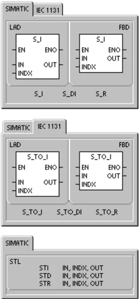
The Substring to Integer and Substring to Double Integer convert strings with the following form: [spaces] [+ or -] [digits 0 - 9]
The Substring to Real instruction converts strings with the following form: [spaces] [+ or -] [digits 0 - 9] [. or ,] [digits 0 - 9]
The INDX value is normally set to 1, which starts the conversion with the first character of the string. The INDX value can be set to other values to start the conversion at different points within the string. This can be used when the input string contains text that is not part of the number to be converted. For example, if the input string is "Temperature: 77.8", you set INDX to a value of 13 to skip over the word "Temperature: " at the start of the string.
The Substring to Real instruction does not convert strings using scientific notation or exponential forms of real numbers. The instruction does not produce an overflow error (SM1.1) but converts the string to a real number up to the exponential and then terminates the conversion. For example, the string '1.234E6' converts without errors to a real value of 1.234.
The conversion is terminated when the end of the string is reached or when the first invalid character is found. An invalid character is any character which is not a digit (0 - 9).
The overflow error (SM1.1) is set whenever the conversion produces an integer value that is too large for the output value. For example, the Substring to Integer instruction sets the overflow error if the input string produces a value greater than 32767 or less than -32768.
The overflow error (SM1.1) is also set if no conversion is possible when the input string does not contain a valid value. For example, if the input string contains 'A123', the conversion instruction sets SM1.1 (overflow) and the output value remains unchanged.
Table 6-20 Valid Operands for the Instructions That Convert Substrings to Numerical Values
S7-200 Instruction Set Chapter 6
Valid Input S strings for Integer and Double Integer
| Input S string | Output Integer |
|---|---|
| '123' | 123 |
| '-00456' | -456 |
| '123.45' | 123 |
| '+2345' | 2345 |
| '000000123ABCD' | 123 |
Valid Input S strings for Real Numbers
| Input S string | Output Real |
|---|---|
| '123' | 123.0 |
| '-00456' | -456.0 |
| '123.45' | 123.45 |
| '+2345' | 2345.0 |
| '00.000000123' | 0.000000123 |
Invalid Input S strings
| Input S string |
|---|
| 'A123' |
| ' ' |
| '++123' |
| '+-123 |
| '+ 123' |
Figure 6-21 Examples of Valid and Invalid Input S strings
Example: String Conversion: Substring to Integer, Double Integer and Real
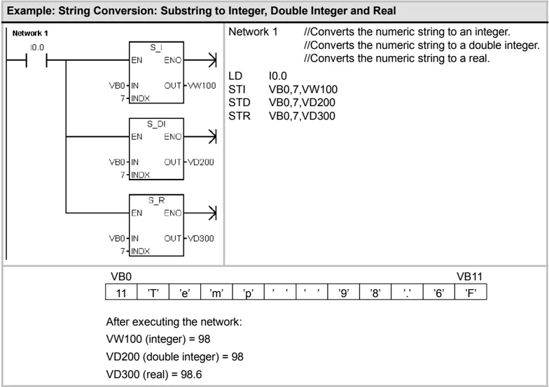
After executing the network: VW100 (integer) = 98 VD200 (double integer) = 98 VD300 (real) = 98.6
111