Table 10-3 shows the Modbus addresses supported by the Modem module, and the mapping of Modbus addresses to the S7-200 CPU addresses.
Use the Modem Expansion wizard to create a configuration block in for the Modem module to support Modbus RTU protocol. The Modem module configuration block must be downloaded to the CPU data block before you can use the Modbus protocol.
Table 10-3 Mapping Modbus Addresses to the S7-200 CPU
| Modbus Address | S7-200 CPU Address |
|---|---|
| 000001 | Q0.0 |
| 000002 | Q0.1 |
| 000003 | Q0.2 |
| ... | ... |
| 000127 | Q15.6 |
| 000128 | Q15.7 |
| 010001 | I0.0 |
| 010002 | I0.1 |
| 010003 | I0.2 |
| ... | ... |
| 010127 | I15.6 |
| 010128 | I15.7 |
| 030001 | AIW0 |
| 030002 | AIW2 |
| 030003 | AIW4 |
| ... | ... |
| 030032 | AIW62 |
| 040001 | VW0 |
| 040002 | VW2 |
| 040003 | VW4 |
| ... | ... |
| 04xxxx | VW 2*(xxxx-1) |
Paging and SMS Messaging
The Modem module supports sending numeric and text paging messages, and SMS (Short Message Service) messages to cellular phones (where supported by the cellular provider). The messages and telephone numbers are stored in the Modem module configuration block which must be downloaded to the data block in the S7-200 CPU. You can use the Modem Expansion wizard to create the messages and telephone numbers for the Modem module configuration block. The Modem Expansion wizard also creates the program code to allow your program to initiate the sending of the messages.
Numeric Paging
Numeric paging uses the tones of a touch tone telephone to send numeric values to a pager. The Modem module dials the requested paging service, waits for the voice message to complete, and then sends the tones corresponding to the digits in the paging message. The digits 0 through 9, asterisk (*), A, B, C and D are allowed in the paging message. The actual characters displayed by a pager for the asterisk and A, B, C, and D characters are not standardized, and are determined by the pager and the paging service provider.
Text Paging
Text paging allows alphanumeric messages to be transmitted to a paging service provider, and from there to a pager. Text paging providers normally have a modem line that accepts text pages. The Modem module uses Telelocator Alphanumeric Protocol (TAP) to transmit the text messages to the service provider. Many providers of text paging use this protocol to accept messages.
Short Message Service (SMS)
Short Message Service (SMS) messaging is supported by some cellular telephone services, generally those that are GSM compatible. SMS allows the Modem module to send a message over an analog telephone line to an SMS provider. The SMS provider then transmits the message to the cellular telephone, and the message appears on the text display of the telephone. The Modem module uses the Telelocator Alphanumeric Protocol (TAP) and the Universal Computer Protocol (UCP) to send messages to the SMS provider. You can send SMS messages only to SMS providers that support these protocols on a modem line.
310
Embedded Variables in Text and SMS Messages
The Modem module can embed data values from the CPU in the text messages and format the data values based on a specification in the message. You can specify the number of digits to the left and right of the decimal point, and whether the decimal point is a period or a comma. When the user program commands the Modem module to transmit a text message, the Modem module retrieves the message from the CPU, determines what CPU values are needed within the message, retrieves those values from the CPU, and then formats and place the values within the text message before transmitting the message to the service provider.
The telephone number of the messaging provider, the message, and the variables embedded within the message are read from the CPU over multiple CPU scan cycles. Your program should not modify telephone numbers or messages while a message is being sent. The variables embedded within a message can continue to be updated during the sending of a message. If a message contains multiple variables, those variables are read over multiple scan cycles of the CPU. If you want all of the embedded variables within a message to be consistent, the you must not change any of the embedded variables after you send a message.
Data Transfers
The Modem module allows your program to transfer data to another CPU or to a Modbus device over the telephone line. The data transfers and telephone numbers are configured with the Modem Expansion wizard, and are stored in the Modem module configuration block. The configuration block is then downloaded to the data block in the S7-200 CPU. The Modem Expansion wizard also creates program code to allow your program to initiate the data transfers.
A data transfer can be either a request to read data from a remote device, or a request to write data to a remote device. A data transfer can read or write between 1 and 100 words of data. Data transfers move data to or from the V memory of the attached CPU.
The Modem Expansion wizard allows you to create a data transfer consisting of a single read from the remote device, a single write to the remote device, or both a read from and a write to the remote device.
Data transfers use the configured protocol of the Modem module. If the Modem module is configured to support PPI protocol (where it responds to STEP 7-Micro/WIN), the Modem module uses the PPI protocol to transfer data. If the Modem module is configured to support the Modbus RTU protocol, data transfers are transmitted using the Modbus protocol.
The telephone number of the remote device, the data transfer request and the data being transferred are read from the CPU over multiple CPU scan cycles. Your program should not modify telephone numbers or messages while a message is being sent. Also, you should not modify the data being transferred while a message is being sent.
If the remote device is another Modem module, the password function can be used by the data transfers by entering the password of the remote Modem module in the telephone number configuration. The callback function cannot be used with data transfers.
Password Protection
The password security of the Modem module is optional and is enabled with the Modem Expansion wizard. The password used by the Modem module is not the same as the CPU password. The Modem module password is a separate 8-character password that the caller must supply to the Modem module before being allowed access to the attached CPU. The password is stored in the V memory of the CPU as part of the Modem module configuration block. The Modem module configuration block must be downloaded to the data block of the attached CPU.
If the CPU has the password security enabled in the System Data Block, the caller must supply the CPU password to gain access to any password protected functions.
Security Callback
The callback function of the Modem module is optional and is configured with the Modem Expansion wizard. The callback function provides additional security for the attached CPU by allowing access to the CPU only from predefined telephone numbers. When the callback function is enabled, the Modem module answers any incoming calls, verifies the caller, and then disconnects the line. If the caller is authorized, the Modem module then dials a predefined telephone number for the caller, and allows access to the CPU.
The Modem module supports three callback modes:
☐ Callback to a single predefined telephone number
☐ Callback to multiple predefined telephone numbers
☐ Callback to any telephone number
The callback mode is selected by checking the appropriate option in the Modem Expansion wizard and then defining the callback telephone numbers. The callback telephone numbers are stored in the Modem module configuration block stored in the data block of the attached CPU.
The simplest form of callback is to a single predefined telephone number. If only one callback number is stored in the Modem module configuration block, whenever the Modem module answers an incoming call, it notifies the caller that callback is enabled, disconnects the caller, and then dials the callback number specified in the configuration block.
The Modem module also supports callback for multiple predefined telephone numbers. In this mode the caller is asked for a telephone number. If the supplied number matches one of the predefined telephone numbers in the Modem module configuration block, the Modem module disconnects the caller, and then calls back using the matching telephone number from the configuration block. The user can configure up to 250 callback numbers.
Where there are multiple predefined callback numbers, the callback number supplied when connecting to the Modem module must be an exact match of the number in the configuration block of the Modem module except for the first two digits. For example, if the configured callback is 91(123)4569999 because of a need to dial an outside line (9) and long distance (1), the number supplied for the callback could be any of the following:
☐ 91(123)4569999
☐ 1(123)4569999
☐ (123)4569999
All of the above telephone number are considered to be a callback match. The Modem module uses the callback telephone number from its configuration block when performing the callback, in this example 91(123)4569999. When configuring multiple callback numbers, make sure that all telephone numbers are unique excluding the first two digits. Only the numeric characters in a telephone number are used when comparing callback numbers. Characters such as commas or parenthesis are ignored when comparing callback numbers.
The callback to any telephone number is set up in the Modem Expansion wizard by selecting the "Enable callbacks to any phone number" option during the callback configuration. If this option is selected, the Modem module answers an incoming call and requests a callback telephone number. After the telephone number is supplied by the caller, the Modem module disconnects and dials that telephone number. This callback mode only provides a means to allow telephone charges to be billed to the Modem module's telephone connection and does not provide any security for the S7-200 CPU. The Modem module password should be used for security if this callback mode is used.
The Modem module password and callback functions can be enabled at the same time. The Modem module requires a caller to supply the correct password before handling the callback.
Creating a Program for the Modem Module Chapter 10
Configuration Table for the Modem Module
All of the text messages, telephone numbers, data transfer information, callback numbers and other options are stored in a Modem module configuration table which must loaded into the V memory of the S7-200 CPU. The Modem Expansion wizard guides you through the creation of a Modem module configuration table. STEP 7-Micro/WIN then places the Modem module configuration table in the Data Block which is downloaded to the S7-200 CPU.
The Modem module reads this configuration table from the CPU on startup and within five seconds of any STOP-to-RUN transition of the CPU. The Modem module does not read a new configuration table from the CPU as long the Modem module is online with STEP 7-Micro/WIN. If a new configuration table is downloaded while the Modem module is online, the Modem module reads the new configuration table when the online session is ended.
If the Modem module detects an error in the configuration table, the Module Good (MG) LED on the front of the module flashes on and off. Check the PLC Information screen in STEP 7-Micro/WIN, or read the value in SMW220 (for module slot 0) for information about the configuration error. The Modem module configuration errors are listed in Table 10-4. If you use the Modem Expansion wizard to create the Modem module configuration table, STEP 7-Micro/WIN checks the data before creating the configuration table.
Table 10-4 EM 241 Configuration Errors (Hexadecimal)
Status LEDs of the Modem Module
The Modem module has 8 status LEDs on the front panel. Table 10-5 describes the status LEDs.
Table 10-5 EM 241 Status LEDs
\begin{tabular}{|l|p{0.8\textwidth}|} \hline LED & Description \ \hline MF & Module Fail - This LED is on when the module detects a fault condition such as: \newline \textbullet{} No 24 VDC external power \newline \textbullet{} Timeout of the I/O watchdog \newline \textbullet{} Modem failure \newline \textbullet{} Communications error with the local CPU \ \hline MG & Module Good - This LED is on when there is no module fault condition. The Module Good LED flashes if there is a error in the configuration table, or the user has selected an illegal country setting for the telephone line interface. Check the PLC Information screen in STEP 7-Micro/WIN or read the value in SMW220 (for module slot 0) for information about the configuration error. \ \hline OH & Off Hook - This LED is on when the EM 241 is actively using the telephone line. \ \hline NT & No Dial Tone - This LED indicates an error condition and turns on when the EM 241 has been commanded to send a message and there is no dial tone on the telephone line. This is only an error condition if the EM 241 has been configured to check for a dial tone before dialing. The LED remains on for approximately 5 seconds after a failed dial attempt. \ \hline RI & Ring Indicator - This LED indicates that the EM 241 is receiving an incoming call. \ \hline CD & Carrier Detect - This LED indicates that a connection has been established with a remote modem. \ \hline Rx & Receive Data - This LED flashes on when the modem is receiving data. \ \hline Tx & Transmit Data - This LED flashes on when the modem is transmitting data. \ \hline \end{tabular}
Using the Modem Expansion Wizard to Configure the Modem Module
Start the Modem Expansion wizard from the STEP 7-Micro/WIN Tools menu or from the Tools portion of the Navigation Bar.
Modem Expansion To use this wizard, the project must be compiled and set to Symbolic Addressing Mode. If you have not already compiled your program, compile it now.
- On first screen of the Modem Expansion wizard, select Configure an EM 241 Modem module and click Next>.
- The Modem Expansion wizard requires the Modem module's position relative to the S7-200 CPU in order to generate the correct program code. Click the Read Modules button to automatically read the positions of the intelligent modules attached to the CPU. Expansion modules are numbered sequentially starting at zero. Double-click the Modem module that you want to configure, or set the Module Position field to the position of the Modem module. Click Next>.
For an S7-200 CPU with firmware prior to version 1.2, you must install the intelligent module next to the CPU in order for the Modem Expansion wizard to configure the module. 3. The password protection screen allows you to enable password protection for the Modem module and assign a 1 to 8 character password for the module. This password is independent of the S7-200 CPU password. When the module is password-protected, anyone who attempts to connect with the S7-200 CPU through the Modem module is required to supply the correct password. Select password protection if desired, and enter a password. Click Next>.
314
-
The Modem module supports two communications protocols: PPI protocol (to communicate with STEP 7-Micro/WIN), and Modbus RTU protocol. Protocol selection is dependent on the type of device that is being used as the remote communications partner. This setting controls the communications protocol used when the Modem module answers a call and also when the Modem module initiates a CPU data transfer. Select the appropriate protocol and click Next>.
-
You can configure the module to send numeric and text messages to pagers, or Short Message Service (SMS) messages to cellular telephones. Check the Enable messaging checkbox and click the Configure Messaging... button to define messages and the recipient's telephone numbers.
-
When setting up a message to be sent to a pager or cellular phone, you must define the message and the telephone number. Select the Messages tab on the Configure Messaging screen and click the New Message button. Enter the text for the message and specify any CPU data values to insert into the message. To insert a CPU data value into the message, move the cursor to the position for the data and click the Insert Data... button. Specify the address of the CPU data value (i.e. VW100), the display format (i.e. Signed Integer) and the digits left and right of the decimal point. You can also specify if the decimal point should be a comma or a period.
- Numeric paging messages are limited to the digits 0 to 9, the letters A, B, C and D, and the asterisk (*). The maximum allowed length of a numeric paging message varies by service provider.
- Text messages can be up to 119 characters in length and contain any alphanumeric character.
- Text messages can contain any number of embedded variables.
- Embedded variables can be from V, M, SM, I, Q, S, T, C or AI memory in the attached CPU.
- Hexadecimal data is displayed with a leading '16#'. The number of characters in the value is based on the size of the variable. For example, VW100 displays as 16#0123.
- The number of digits left of the decimal must be large enough to display the expected range of values, including the negative sign, if the data value is a signed integer or floating point value.
- If the data format is integer and the number of digits right of the decimal point is not zero, the integer value is displayed as a scaled integer. For example, if VW100 = 1234 and there are 2 digits right of the decimal point, the data is displayed as '12.34'.
- If the data value is greater than can be displayed in the specified field size, the Modem module places the # character in all character positions of data value.
- Telephone numbers are configured by selecting the Phone Numbers tab on the Configure Messaging screen. Click the New Phone Number... button to add a new telephone number. Once a telephone number has been configured it must be added to the project. Highlight the telephone number in the Available Phone Numbers column and click the right arrow box to add the telephone number to the current project. Once you have added the telephone number to the current project, you can select the telephone number and add a symbolic name for this number to use in your program.
The telephone number consists of several fields which vary based on the type of messaging selected by the user.
- The Messaging Protocol selection tells the Modem module which protocol to use when sending the message to the message service provider. Numeric pagers support only numeric protocol. Text paging services usually require TAP (Telelocator Alphanumeric Protocol). SMS messaging providers are supported with either TAP or UCP (Universal Computer Protocol). There are three different UCP services normally used for SMS messaging. Most providers support command 1 or 51. Check with the SMS provider to determine the protocol and commands required by that provider.
- The Description field allows you to add a text description for the telephone number.
- The Phone Number field is the telephone number of the messaging service provider. For text messages this is the telephone number of the modem line the service provider uses to accept text messages. For numeric paging this is the telephone number of the pager itself. The Modem module allows the telephone number field to be a maximum of 40 characters. The following characters are allowed in telephone numbers that the Modem module uses to dial out:
- 0 to 9 allowed from a telephone keypad
- A B C D * # DTMF digits (tone dialing only)
- , pause dialing for 2 seconds
- ! commands the modem to generate a hook flash
- @ wait for 5 seconds of silence
- W wait for a dial tone before continuing
- ( )- ignored (can be used to format the telephone number)
The dash character (-) is only supported in Version 1.1 of the EM 241 Modem module.
-
The Specific Pager ID or Cell Phone Number field is where you enter the pager number or cellular telephone number of the message recipient. This number should not contain any characters except the digits 0 through 9. A maximum of 20 characters is allowed.
-
The Password field is optional for TAP message. Some providers require a password but normally this field should be left blank. The Modem module allows the password to be up to 15 characters.
-
The Originating Phone Number field allows the Modem module to be identified in the SMS message. This field is required by some service providers which use UCP commands. Some service providers might require a minimum number of characters in this field. The Modem module allows up to 15 characters.
-
The Modem Standard field is provided for use in cases where the Modem module and the service provider modem cannot negotiate the modem standard. The default is V.34 (33.6 kBaud).
-
The Data Format fields allow you to adjust the data bits and parity used by the modem when transmitting a message to a service provider. TAP normally used 7 data bits and even parity, but some service providers use 8 data bits and no parity. UCP always uses 8 data bits with no parity. Check with the service provider to determine which settings to use.
-
You can configure the Modem module to transfer data to another S7-200 CPU (if PPI protocol was selected) or to transfer data to a Modbus device (if Modbus protocol was selected). Check the Enable CPU data transfers checkbox and click the Configure CPU-to... button to define the data transfers and the telephone numbers of the remote devices.
-
When setting up a CPU-to-CPU or a CPU-to-Modbus data transfer you must define the data to transfer and the telephone number of the remote device. Select the Data Transfers tab on the Configure Data Transfers screen and click the New Transfer button. A data transfer consists of a data read from the remote device, a data write to the remote device, or both a read from and a write to the remote device. If both a read and a write are selected, the read is performed first and then the write.
Up to 100 words can be transferred in each read or write. Data transfers must be to or from the V Memory in the local CPU. The wizard always describes the memory locations in the remote device as if the remote device is an S7-200 CPU. If the remote device is a Modbus device, the transfer is to or from holding registers in the Modbus device (address 04xxxx). The equivalent Modbus address (xxxx) is determined as follows:
Modbus address = 1 + (V memory address / 2) V memory address = (Modbus address - 1) * 2
316
- The Phone Numbers tab on the Configure CPU Data Transfers screen allows you to define the telephone numbers for CPU-to-CPU or a CPU-to-Modbus data transfers. Click the New Phone Number... button to add a new telephone number. Once a telephone number has been configured it must be added to the project. Highlight the telephone number in the Available Phone Numbers column and click the right arrow box to add the telephone number to the current project. Once you have added the telephone number to the current project, you can select the telephone number and add a symbolic name for this telephone number to use in your program.
The Description and Phone Number fields are the same as described earlier for messaging. The Password field is required if the remote device is a Modem module and password protection has been enabled. The Password field in the local Modem module must be set to the password of the remote Modem module. The local Modem module supplies this password when it is requested by the remote Modem module.
-
Callback causes the Modem module to automatically disconnect and dial a predefined telephone number after receiving an incoming call from a remote STEP 7-Micro/WIN. Select the Enable callback checkbox and click the Configure Callback... button to configure callback telephone numbers. Click Next>.
-
The Configure Callback... screen allows you enter the telephone numbers the Modem module uses when it answers an incoming call. Check the 'Enable callbacks to only specified phone numbers' if the callback numbers are to be predefined. If the Modem module is to accept any callback number supplied by the incoming caller (to reverse the connection charges), check the 'Enable callbacks to any phone number' selection.
If only specified callback telephone numbers are allowed, click the New Phone Number button to add callback telephone numbers. The Callback Properties screen allows you to enter the predefined callback telephone numbers and a description for the callback number. The callback number entered here is the telephone number that the Modem module uses to dial when performing the callback. This telephone number should include all digits required to connect to an outside line, pause while waiting for an outside line, connect to long distance, etc.
After entering a new callback telephone number, it must be added to the project. Highlight the telephone number in the Available Callback Phone Numbers column and click the right arrow box to add the telephone number to the current project.
- You can set the number of dialing attempts that the Modem module makes when sending a message or during a data transfer. The Modem module reports an error to the user program only when all attempts to dial and send the message are unsuccessful.
Some telephone lines do not have a dial tone present when the telephone receiver is lifted. Normally, the Modem module returns an error to the user program if a dial tone is not present when the Modem module is commanded to send a message or perform a callback. To allow dialing out on a line with no dial tone, check the box, Enable Dialing Without Dial Tone Selection.
- Version 1.1 of the EM 241 Module can be programmed to answer after a specific number of rings. The module will answer on the first ring unless another value is specified. You can select the answering ring number between 0 and 20. Values of 0 and 1 will answer on the first ring. The value of zero provides compatibility with the previous version of the EM 241.
When using Modbus RTU protocol, Version 1.1 of the EM 241 Module allows the user to configure the module to answer only a specific Modbus address. You can specify Modbus addresses between 0 and 247. An address of zero provides compatibility with the previous version of the EM 241 and causes the EM 241 to answer any address.
-
The Modem Expansion wizard creates a configuration block for the Modem module and requires the user to enter the starting memory address where the Modem module configuration data is stored. The Modem module configuration block is stored in V Memory in the CPU. STEP 7-Micro/WIN writes the configuration block to the project Data Block. The size of the configuration block varies based on the number of messages and telephone numbers configured. You can select the V Memory address where you want the configuration block stored, or click the Suggest Address button if you want the wizard to suggest the address of an unused V Memory block of the correct size. Click Next>.
-
The final step in configuring the Modem module is to specify the Q memory address of the command byte for the Modem module. You can determine the Q memory address by counting the output bytes used by any modules with discrete outputs installed on the
317
S7-200 before the Modem module. Click Next>.
- The Modem Expansion wizard now generates the project components for your selected configuration (program block and data block) and makes that code available for use by your program. The final wizard screen displays your requested configuration project components. You must download the Modem module configuration block (Data Block) and the Program Block to the S7-200 CPU.
Overview of Modem Instructions and Restrictions
The Modem Expansion wizard makes controlling the Modem module easier by creating unique instruction subroutines based on the position of the module and configuration options you selected. Each instruction is prefixed with a "MODx_" where x is the module location.
Requirements for Using the EM 241 Modem Module Instructions
Consider these requirements when you use Modem module instructions:
☐ The Modem module instructions use three subroutines.
☐ The Modem module instructions increase the amount of memory required for your program by up to 370 bytes. If you delete an unused instruction subroutine, you can rerun the Modem Expansion wizard to recreate the instruction if needed.
☐ You must make sure that only one instruction is active at a time.
☐ The instructions cannot be used in an interrupt routine.
☐ The Modem module reads the configuration table information when it first powers up and after a STOP-to-RUN transition. Any change that your program makes to the configuration table is not seen by the module until a mode change or the next power cycle.
Using the EM 241 Modem Module Instructions
To use the Modem module instructions in your S7-200 program, follow these steps:
-
Use the Modem Expansion wizard to create the Modem module configuration table.
-
Insert the MODx_CTRL instruction in your program and use the SM0.0 contact to execute it every scan.
-
Insert a MODx_MSG instruction for each message you need to send.
-
Insert a MODx_XFR instruction for each data transfer.
Instructions for the Modem Module
MODx_CTRL Instruction
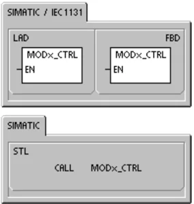
The MODx_CTRL (Control) instruction is used to enable and initialize the Modem module. This instruction should be called every scan and should only be used once in the project.
MODx_XFR Instruction
The MODx_XFR (Data Transfer) instruction is used to command the Modem module to read and write data to another S7-200 CPU or a Modbus device. This instruction requires 20 to 30 seconds from the time the START input is triggered until the Done bit is set.
The EN bit must be on to enable a command to the module, and should remain on until the Done bit is set, signaling completion of the process. An XFR command is sent to the Modem module on each scan when START input is on and the module is not currently busy. The START input can be pulsed on through an edge detection element, which only allows one command to be sent.
Phone is the number of one of the data transfer telephone numbers. You can use the symbolic name you assigned to each data transfer telephone number when the number was defined with the Modem Expansion wizard.
Data is the number of one of the defined data transfers. You can use the symbolic name you assigned to the data transfer when the request was defined using the Modem Expansion wizard.
Done is a bit that comes on when the Modem module completes the data transfer.
Error is a byte that contains the result of the data transfer. Table 10-4 defines the possible error conditions that could result from executing this instruction.
Table 10-6 Parameters for the MODx_XFR Instruction
 \begin{tabular}{|l|l|l|}
\hline
Inputs/Outputs & Data Type & Operands \
\hline
START & BOOL & I, Q, M, S, SM, T, C, V, L, Power Flow \
\hline
Phone, Data & BYTE & VB, IB, QB, MB, SB, SMB, LB, AC, Constant, *VD, *AC, *LD \
\hline
Done & BOOL & I, Q, M, S, SM, T, C, V, L \
\hline
Error & BYTE & VB, IB, QB, MB, SB, SMB, LB, AC, *VD, *AC, *LD \
\hline
\end{tabular}
MODx_MSG Instruction
The MODx_MSG (Send Message) instruction is used to send a paging or SMS message from Modem module. This instruction requires 20 to 30 seconds from the time the START input is triggered until the Done bit is set.
The EN bit must be on to enable a command to the module, and should remain on until the Done bit is set, signaling completion of the process. A MSG command is sent to the Modem module on each scan when START input is on and the module is not currently busy. The START input can be pulsed on through an edge detection element, which only allows one command to be sent.
Phone is the number of one of the message telephone numbers. You can use the symbolic name you assigned to each message telephone number the when the number was defined with the Modem Expansion wizard.
Msg is the number of one of the defined messages. You can use the symbolic name you assigned to the message when the message was defined using the Modem Expansion wizard.
Done is a bit that comes on when the Modem module completes the sending of the message to the service provider.
Error is a byte that contains the result of this request to the module. Table 10-8 defines the possible error conditions that could result from executing this instruction.
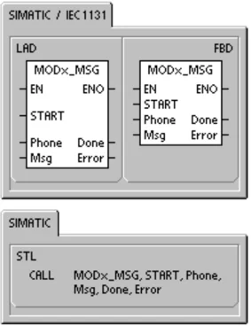
Table 10-7 Parameters for the MODx_MSG Instruction \begin{tabular}{|l|l|l|} \hline Inputs/Outputs & Data Type & Operands \ \hline START & BOOL & I, Q, M, S, SM, T, C, V, L, Power Flow \ \hline Phone, Msg & BYTE & VB, IB, QB, MB, SB, SMB, LB, AC, Constant, *VD, *AC, *LD \ \hline Done & BOOL & I, Q, M, S, SM, T, C, V, L \ \hline Error & BYTE & VB, IB, QB, MB, SB, SMB, LB, AC, *VD, *AC, *LD \ \hline \end{tabular}
Creating a Program for the Modem Module Chapter 10
Table 10-8 Error Values Returned by MODx_MSG and MODx_XFR Instructions
| Error | Description |
|---|---|
| 0 | No error |
| Telephone line errors | |
| 1 | No dial tone present |
| 2 | Busy line |
| 3 | Dialing error |
| 4 | No answer |
| 5 | Connect timeout (no connection within 1 minute) |
| 6 | Connection aborted or an unknown response |
| Errors in the command | |
| 7 | Numeric paging message contains illegal digits |
| 8 | Telephone number (Phone input) out of range |
| 9 | Message or data transfer (Msg or Data input) out of range |
| 10 | Error in text message or data transfer message |
| 11 | Error in messaging or data transfer telephone number |
| 12 | Operation not allowed (i.e. attempts set to zero) |
| Service provider errors | |
| 13 | No response (timeout) from messaging service |
| 14 | Message service disconnected for unknown reason |
| 15 | User aborted message (disabled command bit) |
| TAP - Text paging and SMS message errors returned by service provider | |
| 16 | Remote disconnect received (service provider aborted session) |
| 17 | Login not accepted by message service (incorrect password) |
| 18 | Block not accepted by message service (checksum or transmission error) |
| 19 | Block not accepted by message service (unknown reason) |
| UCP - SMS message errors returned by service provider | |
| 20 | Unknown error |
| 21 | Checksum error |
| 22 | Syntax error |
| 23 | Operation not supported by system (illegal command) |
| 24 | Operation not allowed at this time |
| 25 | Call barring active (blacklist) |
| 26 | Caller address invalid |
| 27 | Authentication failure |
| 28 | Legitimization code failure |
| 29 | GA not valid |
| 30 | Repetition not allowed |
| 31 | Legitimization code for repetition, failure |
| 32 | Priority call not allowed |
| 33 | Legitimization code for priority call, failure |
| 34 | Urgent message not allowed |
| 35 | Legitimization code for urgent message, failure |
| 36 | Reverse charging not allowed |
| 37 | Legitimization code for reverse charging, failure |
321
Table 10-8 Error Values Returned by MODx_MSG and MODx_XFR Instructions, continued
| Error | Description |
|---|---|
| UCP - SMS message errors returned by service provider (continued) | |
| 38 | Deferred delivery not allowed |
| 39 | New AC not valid |
| 40 | New legitimization code not allowed |
| 41 | Standard text not valid |
| 42 | Time period not valid |
| 43 | Message type not supported by system |
| 44 | Message too long |
| 45 | Requested standard text not valid |
| 46 | Message type not valid for pager type |
| 47 | Message not found in SMS C |
| 48 | Reserved |
| 49 | Reserved |
| 50 | Subscriber hang up |
| 51 | Fax group not supported |
| 52 | Fax message type not supported |
| Data transfer errors | |
| 53 | Message timeout (no response from remote device) |
| 54 | Remote CPU busy with upload or download |
| 55 | Access error (memory out of range, illegal data type) |
| 56 | Communications error (unknown response) |
| 57 | Checksum or CRC error in response |
| 58 | Remote EM 241 set for callback (not allowed) |
| 59 | Remote EM 241 rejected the provided password |
| 60 to 127 | Reserved |
| Instruction use errors | |
| 128 | Cannot process this request. Either the Modem module is busy with another request, or there was no START pulse on this request. |
| 129 | Modem module error:• The location of the Modem module or the Q memory address that was configured with the Modem Expansion wizard does not match the actual location or memory address• Refer to SMB8 to SMB21 (I/O Module ID and Error Register) |
322
Creating a Program for the Modem Module Chapter 10
Sample Program for the Modem Module
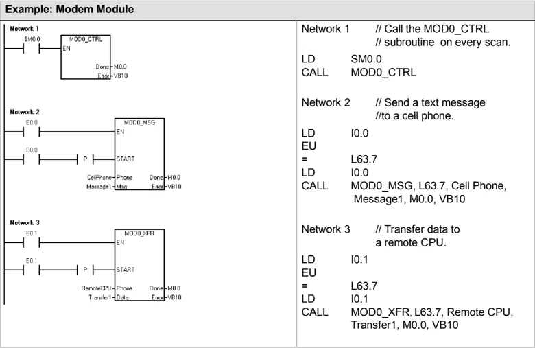
Example: Modem Module
S7-200 CPUs that Support Intelligent Modules
The Modem module is an intelligent expansion module designed to work with the S7-200 CPUs shown in Table 10-9.
Table 10-9 EM 214 Module Compatibility with S7-200 CPUs
| CPU | Description |
|---|---|
| CPU 222 Rel. 1.10 or greater | CPU 222 DC/DC/DC and CPU 222 AC/DC/Relay |
| CPU 224 Rel. 1.10 or greater | CPU 224 DC/DC/DC and CPU 224 AC/DC/Relay |
| CPU 224XP Rel. 2.00 or greater | CPU 224XP DC/DC/DC and CPU 224XP AC/DC/Relay |
| CPU 226 Rel. 1.00 or greater | CPU 226 DC/DC/DC and CPU 226 AC/DC/Relay |
Special Memory Location for the Modem Module
Fifty bytes of special memory (SM) are allocated to each intelligent module based on its physical position in the I/O expansion bus. When an error condition or a change in status is detected, the module indicates this by updating the SM locations corresponding to the module’s position. If it is the first module, it updates SMB200 through SMB249 as needed to report status and error information. If it is the second module, it updates SMB250 through SMB299, and so on. See Table 10-10.
Table 10-10 Special Memory Bytes SMB200 to SMB549
| Intelligent Module in Slot 0 | Intelligent Module in Slot 1 | Intelligent Module in Slot 2 | Intelligent Module in Slot 3 | Intelligent Module in Slot 4 | Intelligent Module in Slot 5 | Intelligent Module in Slot 6 |
|---|---|---|---|---|---|---|
| SMB200 to SMB249 | SMB250 to SMB299 | SMB300 to SMB349 | SMB350 to SMB399 | SMB400 to SMB449 | SMB450 to SMB499 | SMB500 to SMB549 |
Table10-11 shows the Special Memory data area allocated for the Modem module. This area is defined as if this were the intelligent module located in Slot 0 of the I/O system.
323
Table 10-11 S M Locations for the E M 241 Modem Module
| SM Address | Description |
|---|---|
| SMB200 to SMB215 | Module name (16 AS C II characters) SMB200 is the first character. "E M241 Modem" |
| SMB216 to SMB219 | S /W revision number (4 AS C II characters) SMB216 is the first character. |
| SMW220 | Error code0000 - No error0001 - No user power0002 - Modem failure0003 - No configuration block ID0004 - Configuration block out of range0005 - Configuration error0006 - Country code selection error0007 - Phone number too large0008 - Message too large0009 to 00FF - Reserved01xx - Error in callback number xx02xx - Error in pager number xx03xx - Error in message number xx0400 to FFFF - Reserved |
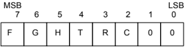
| SMB222 | Module status - reflects the LE D statusMS B 7 6 5 4 3 2 1 0 LS BF G H T R C 0 0F - E M_FAULT 0 - no fault 1 - faultG - E M_GOOD 0 - not good 1 - goodH - OFF_HOOK 0 - on hook, 1 - off hookT - NO DIALTONE 0 - dial tone 1 - no dial toneR - RING 0 - not ringing 1 - phone ringingC - CONNECT 0 - not connected 1 - connected |
| SMB223 | Country code as set by switches (decimal value) |
| SMW224 | Baud rate at which the connection was established (unsigned decimal value). |
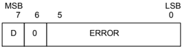
| SMB226 | Result of the user commandMS B 7 6 5 0 LS BD 0 ERRORD - Done bit;0 - operation in progress1 - operation completeERROR : Error Code Description, see Table 10-8 |
| SMB227 | Telephone number selector - This byte specifies which messaging telephone number to use when sending a message. Valid values are 1 through 250. |
| SMB228 | Message selector - This byte specifies which message to send. Valid values are 1 through 250. |
| SMB229 to SMB244 | Reserved |
| SMB245 | Offset to the first Q byte used as the command interface to this module. The offset is supplied by the C P U for the convenience of the user and is not needed by the module. |
| SMD246 | Pointer to the configuration table for the Modem module in V memory. A pointer value to an area other than V memory is not accepted and the module continues to examine this location, waiting for a non-zero pointer value. |
324
Advanced Topics
Understanding the Configuration Table
The Modem Expansion wizard has been developed to make modem applications easy by automatically generating the configuration table based upon the answers you give about your system. Configuration table information is provided for advanced users who want to create their own Modem module control routines and format their own messages.
The configuration table is located in the V memory area of the S7-200. In Table 10-12, the Byte Offset column of the table is the byte offset from the location pointed to by the configuration area pointer in SM memory. The configuration table information is divided into four sections.
☐ The Configuration Block contains information to configure the module.
☐ The Callback Telephone Number Block contains the predefined telephone numbers allowed for callback security.
☐ The Message Telephone Number Block contains the telephone numbers used when dialing messaging services or CPU data transfers.
☐ The Message Block contains the predefined messages to send to the messaging services.
Table 10-12 Configuration Table for the Modem Module Configuration Block
Table 10-12 Configuration Table for the Modem Module, continued
\begin{tabular}{|l|p{0.7\textwidth}|} \hline \multicolumn{2}{|l|}{Callback Telephone Number Block (optional)} \ \hline Byte Offset & Description \ \hline 24 & Callback Telephone Number 1 - A string representing the first telephone number that is authorized for callback access from the EM 241 Modem module. Each callback telephone number must be allocated the same amount of space as specified in the callback telephone number length field (offset 6 in the Configuration Block). \ \hline 24+ callback number & Callback Telephone Number 2 \ \hline : & : \ \hline : & Callback Telephone Number n \ \hline \multicolumn{2}{|l|}{Messaging Telephone Number Block (optional)} \ \hline Byte Offset & Description \ \hline M & Messaging Telephone Number 1 - A string representing a messaging telephone number which includes protocol and dialing options. Each telephone number must be allocated the same amount of space as specified in the messaging telephone number length field (offset 7 in the Configuration Block). The messaging telephone number format is described below \ \hline M + messaging number length & Messaging Telephone Number 2 \ \hline : & : \ \hline : & Messaging Telephone Number n \ \hline \multicolumn{2}{|l|}{Message Block (optional)} \ \hline Byte Offset & Description \ \hline N & V memory offset (relative to VB0) for the first message (2 bytes) \ \hline N+2 & Length of message 1 \ \hline N+3 & Length of message 2 \ \hline : & : \ \hline : & Length of message n \ \hline P & Message 1 - A string (120 bytes max.) representing the first message. This string includes text and embedded variable specifications or it could specify a CPU data transfer. See the Text Message Format and the CPU Data Transfer Format described below. \ \hline P + length of message 1 & Message 2 \ \hline : & : \ \hline : & Message n \ \hline \end{tabular}
The Modem module re-reads the configuration table when these events occur:
- Within five seconds of each STOP-to-RUN transition of the S7-200 CPU (unless the modem is currently online)
- Every five seconds until a valid configuration is found (unless the modem is currently online)
- Every time the modem transitions from an online to an offline condition
326
Messaging Telephone Number Format
The Messaging Telephone Number is a structure which contains the information needed by the Modem module to send a message. The Messaging Telephone Number is an ASCII string with a leading length byte followed by ASCII characters. The maximum length of a Messaging Telephone Number is 120 bytes (which includes the length byte).
The Messaging Telephone Number contains up to 6 fields separated by a forward slash (/) character. Back-to-back slashes indicate an empty (null) field. Null fields are set to default values in the Modem module.
Format: <Telephone Number>/<ID>/<Password>/<Protocol>/<Standard>/<Format>
The Telephone Number field is the telephone number that the Modem module dials when sending a message. If the message being sent is a text or SMS message, this is the telephone number of the service provider. If the message is a numeric page, this field is the pager telephone number. If the message is a CPU data transfer, this is the telephone number of the remote device. The maximum number of characters in this field is 40.
The ID is the pager number or cellular telephone number. This field should consist of the digits 0 to 9 only. If the protocol is a CPU data transfer, this field is used to supply the address of the remote device. Up to 20 characters are allowed in this field.
The Password field is used to supply the a password for messages sent via TAP if a password is required by the service provider. For messages sent via UCP this field is used as the originating address or telephone number. If the message is a CPU data transfer to another Modem module, this field can be used to supply the password of the remote Modem module. The password can be up to 15 characters in length.
The Protocol field consists of one ASCII character which tells the Modem module how it should format and transmit the message. The following values are allowed:
1 - Numeric paging protocol (default) 2 - TAP 3 - UCP command 1 4 - UCP command 30 5 - UCP command 51 6 - CPU data transfer
The Standard field forces the Modem module to use a specific modem standard. The standard field is one ASCII character. The following values are allowed:
1 - Bell 103 2 - Bell 212 3 - V.21 4 - V.22 5 - V.22 bit 6 - V.23c 7 - V.32 8 - V.32 bit 9 - V.34 (default)
The Format field is three ASCII characters which specify the number of data bits and parity to be used when transmitting the message. This field does not apply if the protocol is set to numeric paging. Only the following two settings are allowed:
8N1 - 8 data bits, no parity, one stop bit (default) 7E1 - 7 data bits, even parity, one stop bit
Text Message Format
The Text Message Format defines the format of text paging or SMS messages. These types of messages can contain text and embedded variables. The text message is an ASCII string with a leading length byte followed by ASCII characters. The maximum length of a text message is 120 bytes (which includes the length byte).
Format: <Text><Variable><Text><Variable>...
The Text field consists of ASCII characters.
The Variable field defines an embedded data value which the Modem module reads from the local CPU, formats, and places in the message. The percent (%) character is used to mark the start and the end of a variable field. The address and the left fields are separated with a colon. The delimiter between the Left and Right fields can be either a period or a comma and is used as the decimal point in the formatted variable. The syntax for the variable field is:
% Address :Left.Right Format%
The Address field specifies the address, data type and size of the embedded data value (i.e. VD100, VW50, MB20 or T10). The following data types are allowed: I, Q, M, SM, V, T (word only), C (word only), and AI (word only). Byte, word and double word sizes are allowed.
The Left field defines the number of digits to display left of the decimal point. This value should be large enough to handle the expected range of the embedded variable including a minus sign if needed. If Left is zero the value is displayed with a leading zero. The valid range for Left is 0 to 10.
The Right field defines the number of digits to display right of the decimal point. Zeros to the right of the decimal point are always displayed. If Right is zero the number is displayed without a decimal point. The valid range for Right is 0 to 10.
The Format field specifies the display format of the embedded value. The following characters are allowed for the format field:
i - signed integer u - unsigned integer h - hexadecimal f - floating point/real
Example: "Temperature = %VW100:3.1i% Pressure = %VD200:4.3f%"
328
CPU Data Transfer Message Format
A CPU data transfer, either a CPU-to-CPU or a CPU-to-Modbus data transfer, is specified using the CPU Data Transfer Message Format. A CPU Data Transfer Message is an ASCII string which can specify any number of data transfers between devices, up to the number of specifications that fit in the maximum message length of 120 bytes (119 characters plus a length byte). An ASCII space can be used to separate the data transfer specifications, but is not required. All data transfer specifications are executed within one connection. Data transfers are executed in the order defined in the message. If an error is detected in a data transfer, the connection to the remote device is terminated and subsequent transactions are not processed.
If the operation is specified as a read, Count number of words are read from the remote device starting at the Remote_address, and then written to V Memory in the local CPU starting at the Local_address.
If the operation is specified as a write, Count number of words are read from the local CPU starting at the Local_address, and then written to the remote device starting at Remote_address.
Format: <Operation>=<Count>,<Local_address>,<Remote_address>
The Operation field consists of one ASCII character and defines the type of transfer.
R - Read data from the remote device
W - Write data to the remote device
The Count field specifies the number of words to be transferred. The valid range for the count field is 1 to 100 words.
The Local_address field specifies the V Memory address in the local CPU for the data transfer (i.e. VW100).
The Remote_address field specifies the address in the remote device for the data transfer (i.e. VW500). This address is always specified as a V Memory address even if the data transfer is to a Modbus device. If the remote device is a Modbus device, the conversion between V Memory address and Modbus address is as follows:
Modbus address = 1 + (V Memory address /2)
V Memory address = (Modbus address - 1) *2
Example: R=20,VW100, VW200 W=50,VW500,VW1000 R=100,VW1000,VW2000
Using the USS Protocol Library to Control a MicroMaster Drive
STEP 7-Micro/WIN Instruction Libraries makes controlling MicroMaster drives easier by including preconfigured subroutines and interrupt routines that are specifically designed for using the USS protocol to communicate with a motor drive. You can control the physical drive and the read/write drive parameters with the USS instructions.
You find these instructions in the Libraries folder of the STEP 7-Micro/WIN instruction tree. When you select a USS instruction, one or more associated subroutines (USS1 through USS7) are added automatically.
Siemens Libraries are sold on a separate CD, STEP 7-Micro/WIN Add-On: Instruction Library, with the order number 6ES7 830-2BC00-0YX0. After version 1.1 of the Siemens Library is purchased and installed, any subsequent STEP 7-Micro/WIN V3.2x and V4.0 upgrade that you install will also upgrade your libraries automatically at no additional cost (when library additions or modifications are made).
I n This Chapter
- Requirements for Using the USS Protocol . . . . . . . . . . . . . . . . . . . . . . . . . . . . . . . . . . . . . . . . . . . . . . . . . . . . . . . . . . . . . . . . . . . . . . . . . . . . . . . . . . . . . . . . . . . . . . . . . . . . . . . . . . . . ........ 332
- Calculating the Time Required for Communicating with the Drive . . . . . . . . . . . . . . . . . . . . . . . . . . . . . . . . . . . . . . . . . . . . . . . . . . . . . . . . . . . . . . . . . . . . . . . . . . . . . . . . . . . . . . . . . . . . . . . . . . . . . . . . . . . . . . . . . . . . . . . . . . . . . . . . . . . . . . . . . . . . . . . . . . . . . . . . . . . . . . . . . . . . . . . . . . . . . . . . . . . . . . . . . . . . . . . . . . . . . . . . . . . . . . . . . . . . . . . . ........ 332
- Using the USS Instructions . . . . . . . . . . . . . . . . . . . . . . . . . . . . . . . . . . . . . . . . . . . . . . . . . . . . . . . . . . . . . . . . . . . . . . . . . . . . . . . . . . . . . . . . . . . . . . . . . . . . . . . . . . . ........

Requirements for Using the USS Protocol
The STEP 7-Micro/WIN Instruction Libraries provide subroutines, interrupt routines, and instructions to support the USS protocol. The USS instructions use the following resources in the S7-200:
☐ USS Protocol is an interrupt driven application. In the worst case the receive message interrupt routine requires up to 2.5ms to execute. During this time all other interrupt events are queued for service after the receive message interrupt routine has been executed. If your application cannot tolerate this worst case delay, then you may want to consider other solutions for controlling drives.
☐ Initializing the USS protocol dedicates an S7-200 port for USS communications.
You use the USS_INIT instruction to select either USS or PPI for port 0. (USS refers to the USS protocol for SIMOTION MicroMaster drives.) You can also use USS_INIT_P1 to assign port 1 for USS communication. When a port is set to use the USS protocol for communicating with drives, you cannot use the port for any other purpose, including communicating with STEP 7-Micro/WIN.
During the development of the program for an application using the USS protocol, you should use a two port model, CPU 226, CPU 226XM, or EM 277 PROFIBUS_DP module connected to a PROFIBUS CP card in your computer. The second communications port allows STEP 7-Micro/WIN to monitor the control program while USS protocol is running.
☐ The USS instructions affect all of the SM locations that are associated with Freeport communications on the assigned port.
☐ The USS subroutines and interrupt routines are stored in your program.
☐ The USS instructions increase the amount of memory required for your program by up to 3050 bytes. Depending on the specific USS instructions used, the support routines for these instructions can increase the overhead for the control program by at least 2150 bytes, up to 3500 bytes.
☐ The variables for the USS instructions require a 400-byte block of V memory. The starting address for this block is assigned by the user and is reserved for USS variables.
☐ Some of the USS instructions also require a 16-byte communications buffer. As a parameter for the instruction, you provide a starting address in V memory for this buffer. It is recommended that a unique buffer be assigned for each instance of USS instructions.
☐ When performing calculations, the USS instructions use accumulators AC0 to AC3. You can also use the accumulators in your program; however, the values in the accumulators will be changed by the USS instructions.
☐ The USS instructions cannot be used in an interrupt routine.
Tip To change the operation of a port back to PPI so that you can communicate with STEP 7-Micro/WIN, use another USS_INIT instruction to reassign the port to PPI operation.. You can also set the mode switch on the S7-200 to STOP mode. This resets the parameters for the port. Be aware that stopping the communications to the drives also stops the drives.
Calculating the Time Required for Communicating with the Drive
Communications with the drive are asynchronous to the S7-200 scan. The S7-200 typically completes several scans before one drive communications transaction is completed. The following factors help determine the amount of time required: the number of drives present, the baud rate, and the scan time of the S7-200.
Some drives require longer delays when using the parameter access instructions. The amount of time required for a parameter access is dependent on the drive type and the parameter being accessed.
After a USS_INIT instruction assigns Port 0 to use the USS Protocol (or USS_INIT_P1 for port 1), the S7-200 regularly polls all active drives at the intervals shown in Table 11-1. You must set the time-out parameter of each drive to allow for this task.
Table 11-1 Communications Times
Tip
Only one USS_RPM_x or USS_WPM_x instruction can be active at a time. The Done output of each instruction should signal completion before user logic initiates a new instruction. Use only one USS_CTRL instruction for each drive.
Using the USS Instructions
To use the USS protocol instructions in your S7-200 controller program, follow these steps:
- Insert the USS_INIT instruction in your program and execute the USS_INIT instruction for one scan only. You can use the USS_INIT instruction either to initiate or to change the USS communications parameters.
When you insert the USS_INIT instruction, several hidden subroutines and interrupt routines are automatically added to your program.
- Place only one USS_CTRL instruction in your program for each active drive.
You can add as many USS_RPM_x and USS_WPM_x instructions as required, but only one of these can be active at a time.
- Allocate the V memory for the library instructions by right-clicking (to get the menu) on the Program Block node in the instruction tree.
Select the Library Memory option to display the Library Memory Allocation dialog box.
-
Configure the drive parameters to match the baud rate and address used in the program.
-
Connect the communications cable between the S7-200 and the drives.
Ensure that all of the control equipment, such as the S7-200, that is connected to the drive be connected by a short, thick cable to the same ground or star point as the drive.
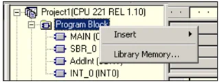
Figure 11-1 Allocating V Memory for the Instruction Library
Caution
Interconnecting equipment with different reference potentials can cause unwanted currents to flow through the interconnecting cable. These unwanted currents can cause communications errors or damage equipment.
Ensure that all equipment that is connected with a communications cable either shares a common circuit reference or is isolated to prevent unwanted current flows.
The shield must be tied to chassis ground or pin 1 on the 9-pin connector. It is recommended that you tie wiring terminal 2-0V on the MicroMaster drive to chassis ground.
Instructions for the USS Protocol
USS_INIT Instruction
The USS_INIT instruction (port 0) or USS_INIT_P1 (port 1) is used to enable and initialize, or to disable MicroMaster Drive communications. Before any other USS instruction can be used, the USS_INIT instruction must be executed without errors. The instruction completes and the Done bit is set immediately, before continuing to the next instruction.
The instruction is executed on each scan when the EN input is on.
Execute the USS_INIT instruction only once for each change in communications state. Use an edge detection instruction to pulse the EN input on. To change the initialization parameters, execute a new USS_INIT instruction.
The value for Mode selects the communications protocol: an input value of 1 assigns a port to USS protocol and enables the protocol, and an input value of 0 assigns port 0 to PPI and disables the USS protocol.
Baud sets the baud rate at 1200, 2400, 4800, 9600, 19200, 38400, 57600 or 115200. Baud rates 57600 and 115200 are supported by S7-200 CPUs version 1.2 or later.

Table 11-2 Parameters for the USS_INIT Instruction
| Inputs/Outputs | Data Type | Operands |
|---|---|---|
| Mode | BYTE | VB, IB, QB, MB, SB, SMB, LB, AC, Constant, *VD, *AC, *LD |
| Baud, Active | DWORD | VD, ID, QD, MD, SD, SMD, LD, Constant, AC *VD, *AC, *LD |
| Done | BOOL | I, Q, M, S, SM, T, C, V, L |
| Error | BYTE | VB, IB, QB, MB, SB, SMB, LB, AC, *VD, *AC, *LD |
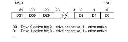
Active indicates which drives are active. Some drives only support addresses 0 through 30.
Figure 11-2 shows the description and format of the active drive input. Any drive that is marked as Active is automatically polled in the background to control the drive, collect status, and prevent serial link time-outs in the drive.
Refer to Table 11-1 to compute the time between status polls.
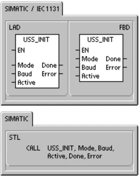
Figure 11-2 Format for the Active Drive Parameter
When the USS_INIT instruction completes, the Done output is turned on. The Error output byte contains the result of executing the instruction. Table 11-6 defines the error conditions that could result from executing the instruction.
Example: USS_INIT Subroutine
334