Technical Specifications Appendix A
EM 231 RTD Module Ranges
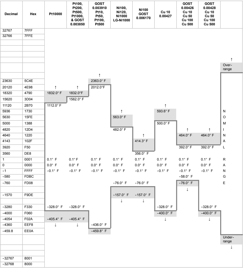
EM 231 RTD temperature ranges and accuracy for each type of RTD module are shown in Tables A-35 and A-36.
Table A-35 Temperature Ranges (°C) and Accuracy for the RTD Module
| Decimal | Hex | Pt10000 | Pt100, Pt200, Pt500, Pt1000, & GOST 0.003850 | GOST 0.003910 Pt10, Pt50, Pt100, Pt500 | Ni100, Ni120, Ni1000 LG-Ni1000 | Ni100 GOST 0.006170 | Cu 10 0.00427 | GOST 0.00426 Cu 10 Cu 50 Cu 100 Cu 500 | GOST 0.00428 Cu 10 Cu 50 Cu 100 Cu 500 | |
|---|---|---|---|---|---|---|---|---|---|---|
| 32767 | 7FFF | |||||||||
| 32766 | 7FFE | |||||||||
| 32511 | 7EFF | |||||||||
| 27649 | 6C01 | |||||||||
| 27648 | 6C00 | |||||||||
| 25000 | 61A8 | |||||||||
| 18000 | 4650 | |||||||||
| 15000 | 3A98 | |||||||||
| 12950 | 3296 | |||||||||
| 11000 | 2AF8 | |||||||||
| 10000 | 2710 | 1000.0°C | 1000.0°C | 1100.0°C | ||||||
| 8500 | 2134 | 850.0°C | ||||||||
| 6000 | 1770 | 600.0°C | ||||||||
| 3120 | 0C30 | |||||||||
| 2950 | 0B86 | 295.0°C | ||||||||
| 2600 | 0A28 | |||||||||
| 2500 | 09C4 | |||||||||
| 2400 | 960 | |||||||||
| 2124 | 84C | □□□.□°C | ||||||||
| 2000 | 7D0 | |||||||||
| 1800 | 708 | |||||||||
| 1 | 0001 | 0.1°C | 0.1°C | 0.1°C | 0.1°C | 0.1°C | 0.1°C | 0.1°C | 0.1°C | R |
| 0 | 0000 | 0.0°C | 0.0°C | 0.0°C | 0.0°C | 0.0°C | 0.0°C | 0.0°C | 0.0°C | A |
| -1 | FFFF | -0.1°C | -0.1°C | -0.1°C | -0.1°C | -0.1°C | -0.1°C | -0.1°C | -0.1°C | N |
| 500 | FE0C | -50.0°C | G | |||||||
| -600 | FDA8 | E | ||||||||
| -1050 | FBE6 | -105.0°C | -105.0°C | |||||||
| -2000 | F830 | -200.0°C | -200.0°C | -200.0°C | -200.0°C | |||||
| -2400 | F6A0 | |||||||||
| -2430 | F682 | -243.0°C | -243.0°C | |||||||
| -2600 | F5D8 | -240.0°C | -240.0°C | |||||||
| -273.2 | F554 | -260.0°C | ||||||||
| -6000 | E890 | -273.2°C | ||||||||
| -10500 | D6FC | |||||||||
| -12000 | D120 | |||||||||
| -32767 | 8001 | |||||||||
| -32768 | 8000 | |||||||||
| ACCURACY OVER FULL SPAN | ±0.4% | ±0.1% | ±0.5% | ±0.2% | ±0.5% | ±0.2% | ±0.3% | ±0.3% | ||
| ACCURACY IN NOMINAL RANGE | ±4°C | ±1°C | ±1°C¹ | ±0.6°C | ±42.8°C | ±1°C | ±1°C | ±1°C |
- OF = Overflow; OR = Over range; NR = Nominal range; UR = Under range; UF = Underflow
↑ or ↓: All analog values exceeding the limits will report the out of range value, 32767 (0x7FFF).
¹Accuracy decreases below -250°C to as great as □°C. - Accuracy may deviate up to +/- 1.5% of full-scale when subjected to severe RF interferences such as specified in the generic immunity standard EN 61000-6-2.
435
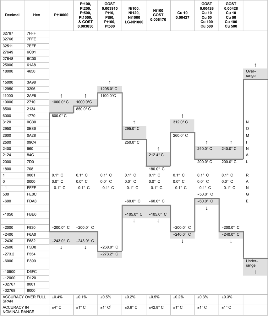
Table A-36 Temperature Ranges (°F) and Accuracy for the RTD Module
| Decimal | Hex | Pt10000 | Pt100, Pt200, Pt500, Pt1000, & GOST 0.003850 | GOST 0.003910 Pt10, Pt50, Pt100, Pt500 | Ni100, Ni120, Ni1000 LG-Ni1000 | Ni100 GOST 0.006170 | Cu 10 0.00427 | GOST 0.00426 Cu 10 Cu 50 Cu 100 Cu 500 | GOST 0.00428 Cu 10 Cu 50 Cu 100 Cu 500 | |
|---|---|---|---|---|---|---|---|---|---|---|
| 32767 | 7FFF | |||||||||
| 32766 | 7FFE | |||||||||
| 23630 | 5C4E | |||||||||
| 20120 | 4E98 | |||||||||
| 18320 | 4790 | 1832.0° F | 1832.0° F | |||||||
| 15620 | 3D04 | 1562.0° F | ||||||||
| 11120 | 2B70 | 1112.0° F | ||||||||
| 5936 | 1730 | |||||||||
| 5630 | 15FE | |||||||||
| 5000 | 1388 | |||||||||
| 4820 | 12D4 | |||||||||
| 4640 | 1220 | |||||||||
| 4143 | 102F | |||||||||
| 3920 | F50 | |||||||||
| 3560 | DE8 | |||||||||
| 1 | 0001 | 0.1° F | 0.1° F | 0.1° F | 0.1° F | 0.1° F | 0.1° F | 0.1° F | 0.1° F | R |
| 0 | 0000 | 0.0° F | 0.0° F | 0.0° F | 0.0° F | 0.0° F | 0.0° F | 0.0° F | 0.0° F | A |
| -1 | FFFF | -0.1° F | -0.1° F | -0.1° F | -0.1° F | -0.1° F | -0.1° F | -0.1° F | -0.1° F | N |
| -580 | FDBC | -58.0° F | G | |||||||
| -760 | FD08 | -76.0° F | -76.0° F | -76.0° F | E | |||||
| -1570 | F9DE | |||||||||
| -3280 | F330 | -328.0° F | -328.0° F | -328.0° F | -328.0° F | |||||
| -4000 | F060 | |||||||||
| -4054 | F02A | -405.4° F | -405.4° F | |||||||
| -4360 | EEF8 | -436.0° F | ||||||||
| -459.8 | EE0A | -459.8° F | ||||||||
| -32767 | 8001 | |||||||||
| -32768 | 8000 |
OF = Overflow; OR = Over range; NR = Nominal range; UR = Under range; UF = Underflow ↑ or ↓: All analog values exceeding the limits will report the out of range value, 32767 (0x7FFF).
436
Technical Specifications Appendix A
Table A-37 Representation of the analog values from 150Ω to 600Ω resistive transducers
| System | Resistive transducer range | |||
|---|---|---|---|---|
| Decimal | Hexadecimal | 150Ω | 300Ω | 600Ω |
| 32767 | 7FFF | 177.77Ω | 355.54Ω | 711.09Ω |
| 32512 | 7F00 | 176.39Ω | 352.78Ω | 705.55Ω |
| 32511 | 7EFF | 176.38Ω | 352.77Ω | 705.53Ω |
| 27649 | 6C01 | 150.01Ω | 300.01Ω | 600.02Ω |
| 27648 | 6C00 | 150Ω | 300Ω | 600Ω |
| 20736 | 5100 | 112.5Ω | 225Ω | 450Ω |
| 1 | 1 | 5.43mΩ | 10.85mΩ | 21.70mΩ |
| 0 | 0 | 0Ω | 0Ω | 0Ω |
| Negative values are physically impossible |
| Overflow | | Overshoot range | | Nominal range | | Undershoot range |
437
EM 277 PROFIBUS-DP Module Specifications
Table A-38 EM 277 PROFIBUS-DP Module Order Number
| Order Number | Expansion Model | EM Inputs | EM Outputs | Removable Connector |
|---|---|---|---|---|
| 6ES7 277-0AA22-0XA0 | EM 277 PROFIBUS-DP | - | - | No |
Table A-39 EM 277 PROFIBUS-DP Module General Specifications
| Order Number | Module Name and Description | Dimensions (mm) (W x H x D) | Weight | Dissipation | VDC Requirements +5 VDC | +24 VDC |
|---|---|---|---|---|---|---|
| 6ES7 277-0AA22-0XA0 | EM 277 PROFIBUS-DP | 71 x 80 x 62 | 175 g | 2.5 W | 150mA | See below |
Table A-40 EM 277 PROFIBUS-DP Module Specifications
| General | 6ES7 277-0AA22-0XA0 |
|---|---|
| Number of Ports (Limited Power) | 1 |
| Electrical interface | RS-485 |
| PROFIBUS-DP/MPI baud rates (set automatically) | 9.6, 19.2, 45.45, 93.75, 187.5, and 500 kbaud; 1, 1.5, 3, 6, and 12 Mbaud |
| Protocols | PROFIBUS-DP slave and MPI slave |
| Cable Length | |
| Up to 93.75 kbaud | 1200 m |
| 187.5 kbaud | 1000 m |
| 500 kbaud | 400 m |
| 1 to 1.5 Mbaud | 200 m |
| 3 to 12 Mbaud | 100 m |
| Network Capabilities | |
| Station address settings | 0 to 99 (set by rotary switches) |
| Maximum stations per segment | 32 |
| Maximum stations per network | 126, up to 99 EM 277 stations |
| MPI Connections | 6 total, 2 reserved (1 for PG and 1 for OP) |
| 24 VDC Input Power Requirements | |
| Voltage range | 20.4 to 28.8 VDC (Class 2, Limited Power, or sensor power from PLC) |
| Maximum current | |
| Module only with port active | 30 mA |
| Add 90 mA of 5V port load | 60 mA |
| Add 120 mA of 24V port load | 180 mA |
| Ripple noise (<10 MHz) | <1 V peak to peak (maximum) |
| Isolation (field to logic)¹ | 500 VAC for 1 minute |
| 5 VDC Power on Communications Port | |
| Maximum current per port | 90 mA |
| Isolation (24 VDC to logic) | 500 VAC for 1 minute |
| 24 VDC Power on Communications Port | |
| Voltage range | 20.4 to 28.8 VDC |
| Maximum current per port | 120 mA |
| Current limit | 0.7 to 2.4 A |
| Isolation | Not isolated, same circuit as input 24 VDC |
¹ No power is supplied to module logic by the 24 VDC supply. 24 VDC supplies power for the communications port.
Technical Specifications Appendix A
S7-200 CPUs that Support Intelligent Modules
The EM 277 PROFIBUS-DP slave module is an intelligent expansion module designed to work with the S7-200 CPUs shown in Table A-41.
Table A-41 EM 277 PROFIBUS-DP Module Compatibility with S7-200 CPUs \begin{tabular}{|l|l|} \hline CPU & Description \ \hline CPU 222 Rel. 1.10 or greater & CPU 222 DC/DC/DC and CPU 222 AC/DC/Relay \ \hline CPU 224 Rel. 1.10 or greater & CPU 224 DC/DC/DC and CPU 224 AC/DC/Relay \ \hline CPU 224XP Rel. 2.0 or greater & CPU 224XP DC/DC/DC and CPU 224XP AC/DC/Relay \ \hline CPU 226 Rel. 1.00 or greater & CPU 226 DC/DC/DC and CPU 226 AC/DC/Relay \ \hline \end{tabular}
Address Switches and LEDs
The address switches and status LEDs are located on the front of the module as shown in Figure A-26. The pin-out for the DP slave port connector is also shown. See Table A-45 for a description of the status LEDs.
Front View of EM 277 PROFIBUS-DP
Address Switches: x10=sets the most significant digit of the address x1= sets the least significant digit of the address
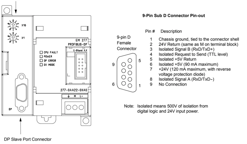
9-Pin Sub D Connector Pin-out
Pin # Description 1 Chassis ground, tied to the connector shell 2 24V Return (same as M on terminal block) 3 Isolated Signal B (RxD/TxD+) 4 Isolated Request to Send (TTL level) 5 Isolated +5V Return 6 Isolated +5V (90 mA maximum) 7 +24V (120 mA maximum, with reverse voltage protection diode) 8 Isolated Signal A (RxD/TxD-) 9 No Connection
Note: Isolated means 500V of isolation from digital logic and 24V input power.
Figure A-26 EM 277 PROFIBUS-DP
439
Distributed Peripheral (DP) Standard Communications
PROFIBUS-DP (or DP Standard) is a remote I/O communications protocol defined by the European Standard EN 50170. Devices that adhere to this standard are compatible even though they are manufactured by different companies. DP stands for distributed peripherals, that is, remote I/O. PROFIBUS stands for Process Field Bus.
The EM 277 PROFIBUS-DP module has implemented the DP Standard protocol as defined for slave devices in the following communications protocol standards:
☐ EN 50 170 (PROFIBUS) describes the bus access and transfer protocol and specifies the properties of the data transfer medium.
☐ EN 50 170 (DP Standard) describes the high-speed cyclic exchange of data between DP masters and DP slaves. This standard defines the procedures for configuration and parameter assignment, explains how cyclic data exchange with distributed I/O functions, and lists the diagnostic options which are supported.
A DP master is configured to know the addresses, slave device types, and any parameter assignment information that the slaves require. The master is also told where to place data that is read from the slaves (inputs) and where to get the data to write to the slaves (outputs). The DP master establishes the network and then initializes its DP slave devices. The master writes the parameter assignment information and I/O configuration to the slave. The master then reads the diagnostics from the slave to verify that the DP slave accepted the parameters and the I/O configuration. The master then begins to exchange I/O data with the slave. Each transaction with the slave writes outputs and reads inputs. The data exchange mode continues indefinitely. The slave devices can notify the master if there is an exception condition and the master then reads the diagnostic information from the slave.
Once a DP master has written the parameters and I/O configuration to a DP slave, and the slave has accepted the parameters and configuration from the master, the master owns that slave. The slave only accepts write requests from the master that owns it. Other masters on the network can read the slave's inputs and outputs, but they cannot write anything to the slave.
Using the EM 277 to Connect an S7-200 as a DP Slave
The S7-200 CPU can be connected to a PROFIBUS-DP network through the EM 277 PROFIBUS-DP expansion slave module. The EM 277 is connected to the S7-200 CPU through the serial I/O bus. The PROFIBUS network is connected to the EM 277 PROFIBUS-DP module through its DP communications port. This port operates at any PROFIBUS baud rate between 9600 baud and 12 Mbaud. See the Specifications for EM 277 PROFIBUS-DP Module for the baud rates supported.
As a DP slave device, the EM 277 module accepts several different I/O configurations from the master, allowing you to tailor the amount of data transferred to meet the requirements of the application. Unlike many DP devices, the EM 277 module does not transfer only I/O data. Inputs, counter values, timer values, or other calculated values can be transferred to the master by first moving the data to the variable memory in the S7-200 CPU. Likewise, data from the master is stored in variable memory in the S7-200 CPU and can be moved to other data areas.
440
Technical Specifications Appendix A
The DP port of the EM 277 PROFIBUS-DP module can be attached to a DP master on the network and still communicate as an MPI slave with other master devices such as SIMATIC programming devices or S7-300/S7-400 CPUs on the same network. Figure A-27 shows a PROFIBUS network with a CPU 224 and an EM 277 PROFIBUS-DP module.
- The CPU 315-2 is the DP master and has been configured by a SIMATIC programming device with STEP 7 programming software.
- The CPU 224 is a DP slave owned by the CPU 315-2. The ET 200 I/O module is also a slave owned by the CPU 315-2.
- The S7-400 CPU is attached to the PROFIBUS network and is reading data from the CPU 224 by means of XGET instructions in the S7-400 CPU user program.
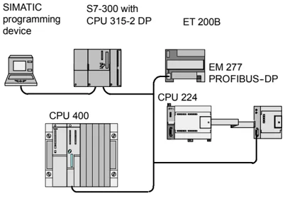
Figure A-27 EM 277 PROFIBUS-DP Module and CPU 224 on a PROFIBUS Network
Configuration
To use the EM 277 PROFIBUS-DP as a DP slave, you must set the station address of the DP port to match the address in the configuration of the master. The station address is set with the rotary switches on the EM 277 module. You must power cycle the CPU after you have made a switch change in order for the new slave address to take effect.
The master device exchanges data with each of its slaves by sending information from its output area to the slave’s output buffer (called a “Receive mailbox”). The slave responds to the message from the master by returning an input buffer (called a “Send mailbox”) which the master stores in an input area.
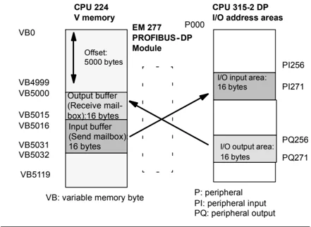
Figure A-28 V Memory and I/O Address Area
Figure A-28 shows an example of the V memory and I/O address area of a PROFIBUS-DP Master.
The EM 277 PROFIBUS-DP can be configured by the DP master to accept output data from the master and return input data to the master. The output and input data buffers reside in the variable memory (V memory) of the S7-200 CPU. When you configure the DP master, you define the byte location in V memory where the output data buffer should start as part of the parameter assignment information for the EM 277. You also define the I/O configuration as the amount of output data to be written to the S7-200 CPU and amount of input data to be returned from the S7-200 CPU. The EM 277 determines the size of the input and output buffers from the I/O configuration. The DP master writes the parameter assignment and I/O configuration information to the EM 277 PROFIBUS DP module. The EM 277 then transfers the V memory address and input and output data lengths to the S7-200 CPU.
Figure A-28 shows a memory model of the V memory in a CPU 224 and the I/O address areas of a DP master CPU. In this example, the DP master has defined an I/O configuration of 16 output bytes and 16 input bytes, and a V memory offset of 5000. The output buffer and input buffer lengths in the CPU 224 (determined from the I/O configuration) are both 16 bytes long. The output data buffer starts at V5000; the input buffer immediately follows the output buffer and begins at V5016. The output data (from the master) is placed in V memory at V5000. The input data (to the master) is taken from the V memory at V5016.
441
Tip If you are working with a data unit (consistent data) of three bytes or data units greater than four bytes, you must use SFC14 to read the inputs of the DP slave and SFC15 to address the outputs of the DP slave. For more information, see the System Software for S7-300 and S7-400 System and Standard Functions Reference Manual.
Table A-42 lists the configurations that are supported by the EM 277 PROFIBUS-DP module. The default configuration for the EM 277 module is two words of input and two words of output.
Table A-42 EM 277 Configuration Options
\begin{tabular}{|l|l|l|l|} \hline Configuration & Inputs to Master & Outputs from Master & Data Consistency \ \hline 1 & 1 word & 1 word & \multirow{12}{}{Word Consistency} \ \cline{1-3} 2 & 2 words & 2 words & \ \cline{1-3} 3 & 4 words & 4 words & \ \cline{1-3} 4 & 8 words & 8 words & \ \cline{1-3} 5 & 16 words & 16 words & \ \cline{1-3} 6 & 32 words & 32 words & \ \cline{1-3} 7 & 8 words & 2 words & \ \cline{1-3} 8 & 16 words & 4 words & \ \cline{1-3} 9 & 32 words & 8 words & \ \cline{1-3} 10 & 2 words & 8 words & \ \cline{1-3} 11 & 4 words & 16 words & \ \cline{1-3} 12 & 8 words & 32 words & \ \hline 13 & 2 bytes & 2 bytes & \multirow{4}{}{Byte Consistency} \ \cline{1-3} 14 & 8 bytes & 8 bytes & \ \cline{1-3} 15 & 32 bytes & 32 bytes & \ \cline{1-3} 16 & 64 bytes & 64 bytes & \ \hline 17 & 4 bytes & 4 bytes & \multirow{4}{*}{Buffer Consistency} \ \cline{1-3} 18 & 8 bytes & 8 bytes & \ \cline{1-3} 19 & 12 bytes & 12 bytes & \ \cline{1-3} 20 & 16 bytes & 16 bytes & \ \hline \end{tabular}
You can configure the location of the input and output buffers to be anywhere in the V memory of the S7-200 CPU. The default address for the input and output buffers is VB0. The location of the input and output buffers is part of the parameter assignment information that the master writes to the S7-200 CPU. You configure the master to recognize its slaves and to write the required parameters and I/O configuration to each of its slaves.
Use the following tools to configure the DP master:
- For SIMATIC S5 masters, use COM PROFIBUS Windows software
- For SIMATIC S7 masters, use STEP 7 programming software
- For SIMATIC 505 masters, use COM PROFIBUS and either TIS OFT2 or SoftShop
For detailed information about using these configuration and programming software packages, refer to the manuals for these devices. For detailed information about the PROFIBUS network and its components, refer to the ET 200 Distributed I/O System Manual.
442
Data Consistency
PROFIBUS supports three types of data consistency:
- Byte consistency ensures that bytes are transferred as whole units.
- Word consistency ensures that word transfers cannot be interrupted by other processes in the CPU (the two bytes composing the word are always moved together and cannot be split). Use Word consistency if the data values being transferred are integers.
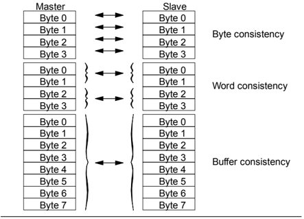
Figure A-29 Byte, Word, and Buffer Data Consistency
- Buffer consistency ensures that the entire buffer of data is transferred as a single unit, uninterrupted by any other process in the CPU. Buffer consistency should be used if the data values are double words or floating point values or when a group of values all relate to one calculation or item.
You set the data consistency as part of the I/O configuration in the master. The data consistency selection is written to the DP slave as part of the initialization of the slave. Both the DP master and the DP slave use the data consistency selection to be sure that data values (bytes, words, or buffers) are transferred uninterrupted within master and slave. The different types of consistency are shown in Figure A-29.
User Program Considerations
Once the EM 277 PROFIBUS-DP module has been successfully configured by a DP master, the EM 277 and the DP master enter data exchange mode. In data exchange mode, the master writes output data to the EM 277 PROFIBUS-DP module, the EM 277 module then responds with most current S7-200 CPU input data. The EM 277 module continuously updates its inputs from the S7-200 CPU in order to provide the most recent input data to the DP Master. The module then transfers the output data to the S7-200 CPU. The output data from the master is placed into V memory (the output buffer) starting at the address that the DP master supplied during initialization. The input data to the master is taken from the V memory locations (the input buffer) immediately following the output data.
The output data from the master must be moved by the user program in the S7-200 CPU from the output buffer to the data areas where it is to be used. Likewise, the input data to the master must be moved from the various data areas to the input buffer for transfer to the master.
Output data from the DP master is placed into V memory immediately after the user program portion of the scan has been executed. Input data (to the master) is copied from V memory to the EM 277 for transfer to the master at the same time.
Output data from the master is only written into V memory when there is new data available from the master.
Input data to the master are transmitted to the master on the next data exchange with the master. The starting address of the data buffers in V memory and the size of the buffers must be known at the time the user program for the S7-200 CPU is created.
Status Information
There are 50 bytes of special memory (SM) allocated to each intelligent module based on its physical position. The module updates the SM locations corresponding to the modules’ relative position to the CPU (with respect to other modules). If it is the first module, it updates SMB200 through SMB249. If it is the second module, it updates SMB250 through SMB299, and so on. See Table A-43.
Table A-43 Special Memory Bytes SMB200 to SMB549
| Intelligent Module in Slot 0 | Intelligent Module in Slot 1 | Intelligent Module in Slot 2 | Intelligent Module in Slot 3 | Intelligent Module in Slot 4 | Intelligent Module in Slot 5 | Intelligent Module in Slot 6 |
|---|---|---|---|---|---|---|
| SMB200 to SMB249 | SMB250 to SMB299 | SMB300 to SMB349 | SMB350 to SMB399 | SMB400 to SMB449 | SMB450 to SMB499 | SMB500 to SMB549 |
These SM locations show default values if DP communications have not been established with a master. After a master has written parameters and I/O configuration to the EM 277 PROFIBUS-DP module, these SM locations show the configuration set by the DP master. You should check the protocol status byte (for example SMB224 for slot 0) to be sure that the EM 277 is currently in data exchange mode with the master before using the information in the SM locations shown in Table A-44, or data in the V memory buffer.
Tip
You cannot configure the EM 277 PROFIBUS-DP I/O buffer sizes or buffer location by writing to SM memory locations. Only the DP master can configure the EM 277 PROFIBUS-DP module for DP operation.
Table A-44 Special Memory Bytes for the EM 277 PROFIBUS-DP
| Intelligent Module in Slot 0 | ... | Intelligent Module in Slot 6 | Description |
|---|---|---|---|
| SMB200 to SMB215 | ... | SMB500 to SMB515 | Module name (16 ASCII characters) "EM277 ProfibusDP" |
| SMB216 to SMB219 | ... | SMB516 to SMB519 | S/W revision number (4 ASCII characters) xxxx |
| SMW220 | ... | SMW520 | Error code16#0000 No error16#0001 No user power16#0002 to 16#FFFF Reserved |
| SMB222 | ... | SMB522 | DP slave module’s station address as set by address switches (0 - 99 decimal) |
| SMB223 | ... | SMB523 | Reserved |
| SMB224 | ... | SMB524 | DP standard protocol status byteMSB LSB0 0 0 0 0 0 S1 S0S1 S0 DP Standard status byte description0 0 DP communications not initiated since power on0 1 Configuration/parameterization error detected1 0 Currently in data exchange mode1 1 Dropped out of data exchange mode |
| SMB225 | ... | SMB525 | DP standard protocol - address of the slave’s master (0 to 126) |
| SMW226 | ... | SMW526 | DP standard protocol - V memory address of the output buffer as an offset from VB0. |
| SMB228 | ... | SMB528 | DP standard protocol - number of bytes of output data |
| SMB229 | ... | SMB529 | DP standard protocol - number of bytes of input data |
| SMB230 to SMB249 | ... | SMB530 to SMB549 | Reserved - cleared on power up |
Note: SM locations are updated each time the DP slave module accepts configuration/parameterization information. These locations are updated even if a configuration/parameterization error is detected. The locations are cleared on each power up.
LED Status Indicators for the EM 277 PROFIBUS-DP
The EM 277 PROFIBUS-DP module has four status LEDs on the front panel to indicate the operational state of the DP port:
After the S7-200 CPU is turned on, the DX MODE LED remains off as long as DP communications are not attempted.
Once DP communications have been successfully initiated (the EM 277 PROFIBUS-DP module has entered data exchange mode with the master), the DX MODE LED turns green and remains on until data exchange mode is exited.
If DP communications are lost, which forces the EM 277 module to exit data exchange mode, the DX MODE LED turns OFF and the DP ERROR LED turns red. This condition persists until the S7-200 CPU is powered off or data exchange is resumed.
If there is an error in the I/O configuration or parameter information that the DP master is writing to the EM 277 module, the DP ERROR LED flashes red.
If user 24 VDC is not provided, the POWER LED will be off.
Table A-45 summarizes the status indications signified by the EM 277 status LEDs.
Table A-45 EM 277 PROFIBUS-DP Module Status LEDs
Note: When the EM 277 PROFIBUS-DP module is used exclusively as an MPI slave, only the green Power LED is on.
Additional Configuration Features
The EM 277 PROFIBUS-DP module can be used as a communications interface to other MPI masters, whether or not it is being used as a PROFIBUS-DP slave. The module can provide a connection from the S7-300/400 to the S7-200 using the XGET/XPUT functions of the S7-300/400. STEP 7-Micro/WIN and a network card (such as the CP5611) using the MPI or PROFIBUS parameter set, an OP device or the TD 200 (Rel. 2.0 or greater, order number 6ES7 272-0AA20-0YA0) can be used to communicate with the S7-200 through the EM 277 PROFIBUS-DP module.
A maximum of six connections (six devices) in addition to the DP master can be connected to the EM 277 PROFIBUS-DP module. One connection is reserved for a programming device (PG) and one is reserved for an operator panel (OP). The other four connections can be used by any MPI master. In order for the EM 277 PROFIBUS-DP module to communicate with multiple masters, all masters must be operating at the same baud rate. See the Figure A-30 for one possible network configuration.
When the EM 277 PROFIBUS-DP module is used for MPI communications, the MPI master must use the station address of the module for all messages that are sent to the S7-200 to which the module is connected. MPI messages sent to the EM 277 PROFIBUS-DP module are passed on to the S7-200.
The EM 277 PROFIBUS-DP module is a slave module and cannot be used for communications between S7-200 PLCs using the NETR and NETW functions. The EM 277 PROFIBUS-DP module cannot be used for Freeport communications.
 Figure A-30 PROFIBUS-DP/MPI Network
Device Database File: GSD
Different PROFIBUS devices have different performance characteristics. These characteristics differ with respect to functionality (for example, the number of I/O signals and diagnostic messages) or bus parameters, such as transmission speed and time monitoring. These parameters vary for each device type and vendor, and are usually documented in a technical manual. To help you achieve a simple configuration of PROFIBUS, the performance characteristics of a particular device are specified in an electronic data sheet called a device database file, or GSD file. Configuration tools based on GSD files allow simple integration of devices from different vendors in a single network.
The device database file provides a comprehensive description of the characteristics of a device in a precisely defined format. These GSD files are prepared by the vendor for each type of device and made available to the PROFIBUS user. The GSD file allows the configuration system to read in the characteristics of a PROFIBUS device and use this information when configuring the network.
The latest versions of the COM PROFIBUS or STEP 7 software include configuration files for the EM 277 PROFIBUS-DP Module. If your version of software does not include a configuration file for the EM 277, you can access the latest GSD file (SIEM089D.GSD) at website www.profibus.com.
If you are using a non-Siemens master device, refer to the documentation provided by the manufacturer on how to configure the master device by using the GSD file.
446
Technical Specifications Appendix A
;============================================== ; GSD File for the EM 277 PROFIBUS-DP with a DPC31 ; MLFB : 6ES7 277-0AA2.-0XA0 ; DATE : 26-March-2001 ;============================================== #Profibus_DP ;General parameters GSD_Revision = 1 Vendor_Name = "Siemens" Model_Name = "EM 277 PROFIBUS-DP" Revision = "V1.02" Ident_Number = 0x089D Protocol_Ident = 0 Station_Type = 0 FMS_supp = 0 Hardware_Release = "1.00" Software_Release = "1.02" 9.6_supp = 1 19.2_supp = 1 45.45_supp = 1 93.75_supp = 1 187.5_supp = 1 500_supp = 1 1.5M_supp = 1 3M_supp = 1 6M_supp = 1 12M_supp = 1 MaxTsdr_9.6 = 60 MaxTsdr_19.2 = 60 MaxTsdr_45.45 = 250 MaxTsdr_93.75 = 60 MaxTsdr_187.5 = 60 MaxTsdr_500 = 100 MaxTsdr_1.5M = 150 MaxTsdr_3M = 250 MaxTsdr_6M = 450 MaxTsdr_12M = 800 Redundancy = 0 Repeater_Ctrl_Sig = 2 24V_Pins = 2
; Slave-Specification: OrderNumber="6ES7 277-0AA2.-0XA0" Periphery="SIMATIC S5" Slave_Family=10@TdF@SIMATIC Freeze_Mode_supp = 1 Sync_Mode_supp = 1 Set_Slave_Add_Supp = 0 Auto_Baud_supp = 1 Min_Slave_Intervall = 1 Fail_Safe = 0 Max_Diag_Data_Len = 6 Modul_Offset = 0 Modular_Station = 1 Max_Module = 1 Max_Input_len = 128 Max_Output_len = 128 Max_Data_len = 256
; UserPrmData-Definition ExtUserPrmData=1 "I/O Offset in the V-memory" Unsigned16 0 0-10239 EndExtUserPrmData ; UserPrmData: Length and Preset: User_Prm_Data_Len=3 User_Prm_Data= 0,0,0 Max_User_Prm_Data_Len=3 Ext_User_Prm_Data_Const(0)=0x00,0x00,0x00 Ext_User_Prm_Data_Ref(1)=1
;============================================== ; Continuation of GSD File ;============================================== ; Module Definition List Module = "2 Bytes Out/ 2 Bytes In -" 0x31 EndModule Module = "8 Bytes Out/ 8 Bytes In -" 0x37 EndModule Module = "32 Bytes Out/ 32 Bytes In -" 0xC0,0x1F,0x1F EndModule Module = "64 Bytes Out/ 64 Bytes In -" 0xC0,0x3F,0x3F EndModule Module = "1 Word Out/ 1 Word In -" 0x70 EndModule Module = "2 Word Out/ 2 Word In -" 0x71 EndModule Module = "4 Word Out/ 4 Word In -" 0x73 EndModule Module = "8 Word Out/ 8 Word In -" 0x77 EndModule Module = "16 Word Out/ 16 Word In -" 0x7F EndModule Module = "32 Word Out/ 32 Word In -" 0xC0,0x5F,0x5F EndModule Module = "2 Word Out/ 8 Word In -" 0xC0,0x41,0x47 EndModule Module = "4 Word Out/ 16 Word In -" 0xC0,0x43,0x4F EndModule Module = "8 Word Out/ 32 Word In -" 0xC0,0x47,0x5F EndModule Module = "8 Word Out/ 2 Word In -" 0xC0,0x47,0x41 EndModule Module = "16 Word Out/ 4 Word In -" 0xC0,0x4F,0x43 EndModule Module = "32 Word Out/ 8 Word In -" 0xC0,0x5F,0x47 EndModule Module = "4 Byte buffer I/O -" 0xB3 EndModule Module = "8 Byte buffer I/O -" 0xB7 EndModule Module = "12 Byte buffer I/O -" 0xBB EndModule Module = "16 Byte buffer I/O -" 0xBF EndModule
Figure A-31 Listing of the GSD File for the EM 277 PROFIBUS Module
447
Sample Program for DP Communications to a CPU
A sample program in Statement List for the PROFIBUS-DP module in slot 0 for a CPU that uses the DP port information in SM memory is shown below. The program determines the location of the DP buffers from SMW226 and the sizes of the buffers from SMB228 and SMB229. This information is used to copy the data in the DP output buffer to the process-image output register of the CPU. Similarly, the data in the process-image input register of the CPU are copied into the V memory input buffer.
In the following sample program for a DP module in position 0, the DP configuration data in the SM memory area provides the configuration of the DP slave. The program uses the following data:
| Address | Description |
|---|---|
| SMW220 | DP Module Error Status |
| SMB224 | DP Status |
| SMB225 | Master Address |
| SMW226 | V memory offset of outputs |
| SMB228 | Number of bytes of output data |
| SMB229 | Number of bytes of input data |
| VD1000 | Output Data Pointer |
| VD1004 | Input Data Pointer |
Technical Specifications Appendix A
Example of DP Communications to a CPU
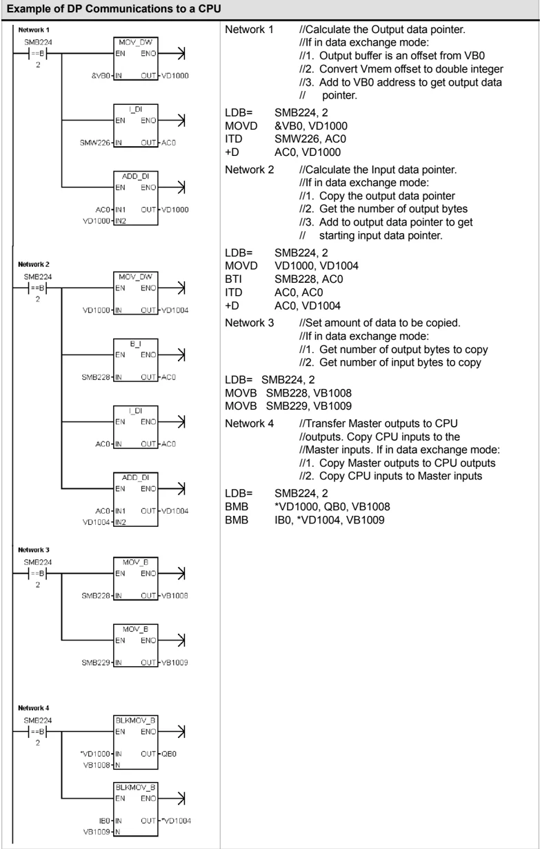
Network 1 //Calculate the Output data pointer. //If in data exchange mode: //1. Output buffer is an offset from VB0 //2. Convert Vmem offset to double integer //3. Add to VB0 address to get output data // pointer.
LDB= SMB224, 2 MOVD &VB0, VD1000 ITD SMW226, AC0 +D AC0, VD1000
Network 2 //Calculate the Input data pointer. //If in data exchange mode: //1. Copy the output data pointer //2. Get the number of output bytes //3. Add to output data pointer to get // starting input data pointer.
LDB= SMB224, 2 MOVD VD1000, VD1004 BTI SMB228, AC0 ITD AC0, AC0 +D AC0, VD1004
Network 3 //Set amount of data to be copied. //If in data exchange mode: //1. Get number of output bytes to copy //2. Get number of input bytes to copy
LDB= SMB224, 2 MOVB SMB228, VB1008 MOVB SMB229, VB1009
Network 4 //Transfer Master outputs to CPU //outputs. Copy CPU inputs to the //Master inputs. If in data exchange mode: //1. Copy Master outputs to CPU outputs //2. Copy CPU inputs to Master inputs
LDB= SMB224, 2 BMB *VD1000, QB0, VB1008 BMB IB0, *VD1004, VB1009
449
EM 241 Modem Module Specifications
Table A-46 EM 241 Modem Module Order Number
| Order Number | Expansion Model | EM Inputs | EM Outputs | Removable Connector |
|---|---|---|---|---|
| 6ES7 241-1AA22-0XA0 | EM 241 Modem Module | - | 8¹ | No |
¹ Eight Q outputs are used as logical controls of the modem function and do not directly control any external signals.
Table A-47 EM 241 Modem Module General Specifications
| Order Number | Module Name and Description | Dimensions (mm) (W x H x D) | Weight | Dissipation | VDC Requirements +5 VDC | +24 VDC |
|---|---|---|---|---|---|---|
| 6ES7 241-1AA22-0XA0 | EM 241 Modem Module | 71.2 x 80 x 62 | 190 g | 2.1 W | 80 mA | 70 mA |
Table A-48 EM 241 Modem Module Specifications
| General | 6ES7 241-1AA22-0XA0 |
|---|---|
| Telephone Connection | |
| Isolation (phone line to logic and field power) | 1500 VAC (Galvanic) |
| Physical connection | RJ 11 (6 position, 4 wire) |
| Modem standards | Bell 103, Bell 212, V.21, V.22, V.22 bis, V.23c, V.32, V.32 bis, V.34 (default) |
| Security features | PasswordCallback |
| Dialing | Pulse or Tone |
| Messaging Protocols | NumericTAP (alphanumeric)UCP commands 1, 30, 51 |
| Industrial Protocols | ModbusPPI |
| 24 VDC Input Power Requirements | |
| Voltage range | 20.4 to 28.8 VDC |
| Isolation (field power to logic) | 500 VAC for 1 minute |
The EM 241 Modem Module replaces the function of an external modem connected to the communications port of the CPU. With an EM 241 installed in your S7-200 system, all you need to communicate with your CPU from a remote location is a personal computer with an external modem and STEP 7-Micro/WIN.
See Chapter 7, Communicating over a Network, for information on configuring. See Chapter 10, Creating a Program for the Modem Module for programming and advanced features of the module.
You can use the STEP 7-Micro/WIN Modem Expansion Wizard to configure an EM 241 Modem Module. See Chapter 10 for more information about the Modem Expansion Wizard.

Figure A-32 EM 241 Modem Module Terminal Block Diagram
450
Technical Specifications Appendix A
S7-200 CPUs that Support Intelligent Modules
The EM 241 Modem module is an intelligent expansion module designed to work with the S7-200 CPUs shown in Table A-49.
Table A-49 EM 241 Modem Module Compatibility with S7-200 CPUs
| CPU | Description |
|---|---|
| CPU 222 Rel. 1.10 or greater | CPU 222 DC/DC/DC and CPU 222 AC/DC/Relay |
| CPU 224 Rel. 1.10 or greater | CPU 224 DC/DC/DC and CPU 224 AC/DC/Relay |
| CPU 224XP Rel 2.0 or greater | CPU 224XP DC/DC/DC and CPU 224XP DC/DC/Relay |
| CPU 226 Rel. 1.00 or greater | CPU 226 DC/DC/DC and CPU 226 AC/DC/Relay |
Installing the EM 241
Follow these steps to install the EM 241:
- Snap the EM 241 on the DIN rail and plug in the ribbon cable.
- Connect 24 VDC from the CPU sensor supply or external source, and connect the ground terminal to your system earth ground.
- Plug the phone line into the RJ 11 jack.
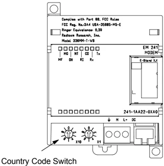
- Set the country code switches according to Table A-50. You must set the switches before power is applied to the CPU for the correct country code to be read.
- Power the CPU. The green MG (Module Good) light should come on.
Your EM 241 is now ready to communicate.
Table A-50 Country Codes Supported by EM 241
| Code | Country | Telecom Standard |
|---|---|---|
| 00 | Australia | ACA TS-002 |
| 01 | Austria | CTR 21 |
| 02 | Belgium | CTR 21 |
| 05 | Canada | IC CS 03 |
| 06 | China | GB3482 |
| 08 | Denmark | CTR 21 |
| 09 | Finland | CTR 21 |
| 10 | France | CTR 21 |
| 11 | Germany | CTR 21 |
| 12 | Greece | CTR 21 |
| 16 | Ireland | CTR 21 |
| 18 | Italy | CTR 21 |
| 22 | Luxembourg | CTR 21 |
| 25 | Netherlands | CTR 21 |
| 26 | New Zealand | PTC 200 |
| 27 | Norway | CTR 21 |
| 30 | Portugal | CTR 21 |
| 34 | Spain | CTR 21 |
| 35 | Sweden | CTR 21 |
| 36 | Switzerland | CTR 21 |
| 38 | U.K. | CTR 21 |
| 39 | U.S.A. | FCC Part 68 |
RJ 11 Jack
Figure A-33 shows the details of the RJ 11 Jack. You can use adaptors to other standard telephone connectors. Refer to your adaptor connector documentation for more information.
 Figure A-33 View of RJ 11 Jack
| Pin | Description |
|---|---|
| 3 | Ring |
| 4 | Tip |
Reverse connection is allowed.
Caution
Lightning surges or other unexpected high voltages on the telephone line can damage your EM 241 Modem Module.
Use a commercially available telephone line surge protector, such as are commonly sold for protection of personal computer modems. Surge protectors can be damaged as they protect your EM 241 Modem Module. Choose a surge protector with a positive indicator that shows it is functional.
Check your surge protector regularly to ensure that your EM 241 Modem Module continues to be protected.
451
EM 253 Position Module Specifications
Table A-51 EM 253 Position Module Order Number
$^{1}$ Eight Q outputs are used as logical controls of the motion function and do not directly control any external signals.
Table A-52 EM 253 Position Module General Specifications
Table A-53 EM 253 Position Module Specifications
Technical Specifications Appendix A
Table A-53 EM 253 Position Module S Specifications, continued
| General | 6ES7 253-1AA22-0XA0 |
|---|---|
| Output Features | |
| Number of integrated outputs | 6 points (4 signals) |
| Output typeP0+, P0-, P1+, P1-P0, P1, DIS, CLR | RS □□□/□□□ driverOpen drain |
| Output voltageP0, P1, RS -422 drivers, differential output voltageOpen circuitInto optocoupler diode with 200Ω series resistance100Ω load54Ω loadP0, P1, DIS, CLR open drainrecommended voltage, open circuitpermissible voltage, open circuitSink currentOn state resistanceOff state leakage current, 30 VDCInternal Pull up resistor, output drain to T1 | 3.5 V typical2.8 V minimum1.5 V minimum1.0 V minimum5 VDC, available from module30 VDC¹50 mA maximum15Ω maximum10 μA maximum3.3K Ω² |
| Output currentNumber of output groupsOutputs on simultaneouslyLeakage current per pointP0, P1, DIS, CLROverload Protection | 1All at 55° C (horizontal), All at 45° C (vertical)10 μA maximumNo |
| Isolation (field to logic)Optical Isolation (Galvanic) | 500 VAC for 1 minute |
| Output delayDIS, CLR: Off to On / On to Off | 30 μs, maximum |
| Pulse distortionP0, P1, outputs, RS -422 drivers, 100 Ω external loadP0, P1 outputs, open drain, 5 V / 470 Ω external load | 75 ns maximum300 ns maximum |
| Switching frequencyP0+, P0-, P1+, P1-, P0 and P1 | 200 kHz |
| Cable lengthUnshieldedShielded | Not recommended10 meters |
| Power Supply | |
| L+ supply voltageLogic supply outputL+ supply current vs. 5 VDC loadLoad current0 mA (no load)200 mA (rated load) | 11 to 30 VDC (Class 2, Limited Power, or sensor power from PLC)+5 VDC +/- 10%, 200 mA maximum |
| 12 VDC Input120 mA300 mA | |
| 24 VDC Input70 mA130 mA | |
| IsolationL+ power to logicL+ power to inputsL+ power to outputs | 500 VAC for 1 minute500 VAC for 1 minuteNone |
| Reverse Polarity | L+ input and +5V output are diode-protected. Placing a positive voltage on any M terminal with respect to output point connections can result in potentially damaging current flow. |
¹ Operation of open drain outputs above 5 VDC may increase radio frequency emissions above permissible limits. Radio frequency containment measures may be required for your system or wiring.
² Depending on your pulse receiver and cable, an additional external pull up resistor may improve pulse signal quality and noise immunity.
453
S7-200 CPUs that Support Intelligent Modules
The EM 253 Position module is an intelligent expansion module designed to work with the S7-200 CPUs shown in Table A-54.
Table A-54 EM 253 Position Module Compatibility with S7-200 CPUs \begin{tabular}{|l|l|} \hline CPU & Description \ \hline CPU 222 Rel. 1.10 or greater & CPU 222 DC/DC/DC and CPU 222 AC/DC/Relay \ \hline CPU 224 Rel. 1.10 or greater & CPU 224 DC/DC/DC and CPU 224 AC/DC/Relay \ \hline CPU 224XP Rel 2.0 or greater & CPU 224XP DC/DC/DC and CPU 224XP DC/DC/Relay \ \hline CPU 226 Rel. 1.00 or greater & CPU 226 DC/DC/DC and CPU 226 AC/DC/Relay \ \hline \end{tabular}
EM 253 Position Module Status LEDs
The Status LEDs for the Position Modules are shown in Table A-55.
Table A-55 Position Module Status LEDs \begin{tabular}{|l|l|l|l|} \hline Local I/O & LED & Color & Function Description \ \hline
- & MF & Red & Illuminated when module detects a fatal error \ \hline
- & MG & Green & Illuminated when there is no module fault, and flashes at 1 Hz rate when a configuration error is detected \ \hline
- & PWR & Green & Illuminated when 24 VDC is supplied on the L+ and M terminals of the module \ \hline Input & STP & Green & Illuminated when the stop input is on \ \hline Input & RPS & Green & Illuminated when the reference point switch input is on \ \hline Input & ZP & Green & Illuminated when the zero pulse input is on \ \hline Input & LMT- & Green & Illuminated when the negative limit input is on \ \hline Input & LMT + & Green & Illuminated when the positive limit input is on \ \hline Output & P0 & Green & Illuminated when the P0 output is pulsing \ \hline Output & P1 & Green & Illuminated when the P1 output is pulsing or when this output indicates positive motion \ \hline Output & DIS & Green & Illuminated when the DIS output is active \ \hline Output & CLR & Green & Illuminated when the clear deviation counter output is active \ \hline \end{tabular}
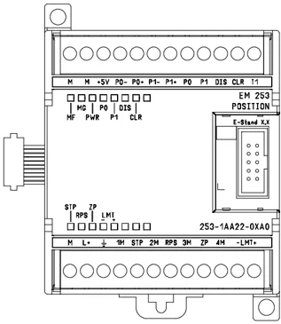
Figure A-34 EM 253 Position Module
454
Technical Specifications Appendix A
Wiring Diagrams
In the following schematic figures, the terminals are not in order. See Figure A-34 for terminal arrangement.
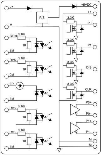
Figure A-35 Internal Schematic for the Inputs and Outputs of the EM 253 Position Module
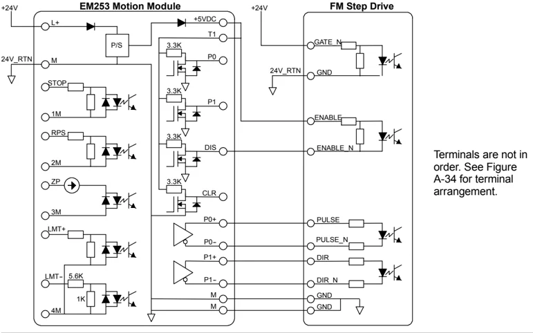
Terminals are not in order. See Figure A-34 for terminal arrangement.
Figure A-36 Connecting an EM 253 Position Module to a SIMATIC FM Step Drive
455
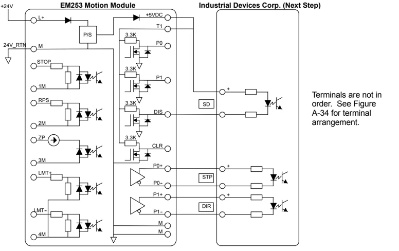
Figure A-37 Connecting an EM 253 Position Module to a Industrial Devices Corp. (Next Step)
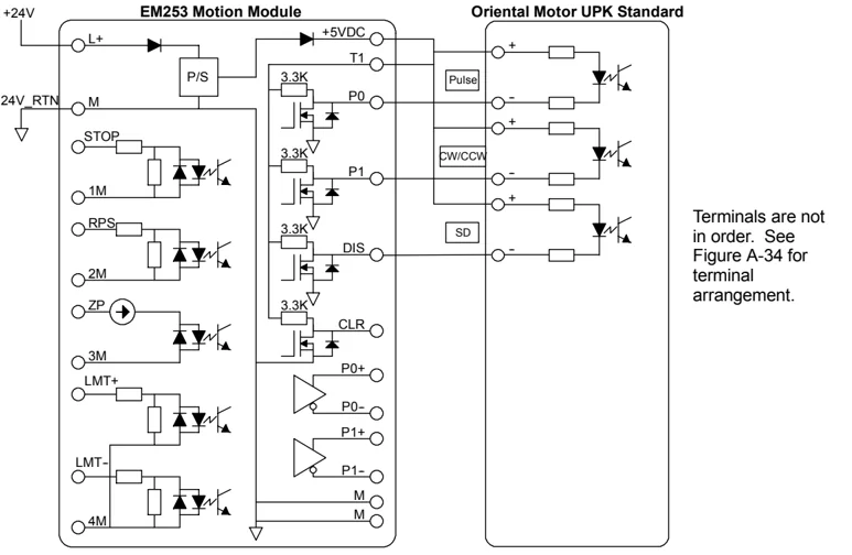
Figure A-38 Connecting an EM 253 Position Module to an Oriental Motor UPK Standard
456
Technical Specifications Appendix A
 Figure A-39 Connecting an EM 253 Position Module to a Parker/Compumotor OEM 750
457
(CP 243-1) Ethernet Module Specifications
Table A-56 (CP 243-1) Ethernet Module Order Number
| Order Number | Expansion Module | EM Inputs | EM Outputs | Removable Connector |
|---|---|---|---|---|
| 6GK7 243-1EX00-OXE0 | (CP 243-1) Ethernet Module | - | 8¹ | No |
¹ Eight Q outputs are used as logical controls of Ethernet function and do not directly control any external signals.
Table A-57 (CP 243-1) Ethernet Module General Specifications
| Order Number | Module Name and Description | Dimensions (mm) (W x H x D) | Weight | Dissipation | VDC Requirement +5 VDC | +24 VDC |
|---|---|---|---|---|---|---|
| 6GK7 243-1EX00-OXE0 | (CP 243-1) Ethernet Module | 71.2 x 80 x 62 | approx. 150 g | 1.75 W | 55 mA | 60 mA |
Table A-58 (CP 243-1) Ethernet Module Specifications
| General | 6GK7 243-1EX00-OXE0 |
|---|---|
| Transmission Rate | 10 Mbits/s and 100 Mbits/s |
| Flash memory size | 1 Mbyte |
| SDRAM memory size | 8 Mbyte |
| Interface | 8-pin RJ 45 socket |
| Connection to Industrial Ethernet (10/100 Mbit/s) | |
| Input voltage | 20.4 to 28.8 VDC |
| Maximum connections | Maximum of 8 S7 connections (XPUT/XGET and READ/WRITE) plus 1 connection to STEP 7-Micro/WIN per (CP 243-1) Ethernet Module² |
| Starting time or restart time after a reset | Approx. 10 seconds |
| User data quantities | As client: up to 212 bytes for XPUT/XGETAs server: up to 222 bytes for XGET or READup to 212 bytes for XPUT or WRITE |
² Only one (CP 243-1) Ethernet module should be connected per S7-200 CPU.
The (CP 243-1) Ethernet module is a communications processor used for connecting the S7-200 system to Industrial Ethernet (IE). The S7-200 can be remotely configured, programmed and diagnosed via Ethernet using STEP 7 Micro/WIN. The S7-200 can communicate with another S7-200, S7-300, or S7-400 controller via Ethernet. It can also communicate with an OPC server.
Industrial Ethernet is designed for industry. It can be used with either noise-free industrial twisted pair (ITP) technology, or the Industry-standard twisted pair (TP) technology. Industrial Ethernet can be implemented to offer a wide range of application specific uses, such as switching, high-speed redundancy, fast connects, and redundant networks. Using the (CP 243-1) Ethernet module, the S7-200 PLC is made compatible with a wide range of existing products that support Ethernet.
S7-200 CPUs that Support Intelligent Modules
The (CP 243-1) Ethernet module is an intelligent expansion module designed to work with the S7-200 CPUs shown in Table A-49.
Table A-59 (CP 243-1) Ethernet Module Compatibility with S7-200 CPUs
| CPU | Description |
|---|---|
| CPU 222 Rel. 1.10 or greater | CPU 222 DC/DC/DC and CPU 222 AC/DC/Relay |
| CPU 224 Rel. 1.10 or greater | CPU 224 DC/DC/DC and CPU 224 AC/DC/Relay |
| CPU 224XP Rel. 2.00 or greater | CPU 224XP DC/DC/DC and CPU 224XP AC/DC/Relay |
| CPU 226 Rel. 1.00 or greater | CPU 226 DC/DC/DC and CPU 226 AC/DC/Relay |
The (CP 243-1) Ethernet module is delivered with a preset, unique worldwide MAC address that cannot be changed.
Functions
The (CP 243-1) Ethernet module independently handles data traffic over the Industrial Ethernet.
- Communication is based on TCP/IP
- For communication between S7-200 CPUs and other S7 control systems or PCs via Ethernet, communication services are available as Client and Server. Up to eight connects can be operated.
- The implementation of PC applications is possible by integration of the S7-OPC Server
- The (CP 243-1) Ethernet module allows direct access of the S7-200 programming software, STEP 7-Micro/WIN to S7-200 via Ethernet
Configuration
You can use the STEP 7-Micro/WIN Ethernet Wizard to configure the (CP 243-1) Ethernet module to connect an S7-200 PLC to an Ethernet network. The Ethernet wizard helps you define the parameters for the (CP 243-1) Ethernet module and then places the configuration instructions in your project instruction folder. To start the Ethernet Wizard, select the Tools > Ethernet Wizard menu command. The wizard uses the following information: IP Address, Subnet Mask, Gateway Address, and communications connection type.
Connections
The (CP 243-1) Ethernet module has the following connections. The connections are located under the covers of the front doors.
- Terminal block for 24 VDC supply voltage and ground connection
- 8-in RJ 45 socket for Ethernet connection
- Plug connector for I/O bus
- Integrated ribbon cable with socket for I/O bus
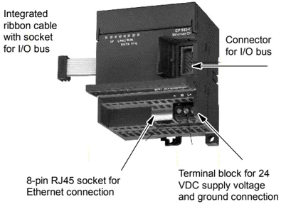
Figure A-40 Connecting the (CP 243-1) Ethernet Module
Additional Information
For more information about the (CP 243-1) Ethernet module, refer to the SIMATIC NET CP 243-1 Communications Processor for Industrial Ethernet Technical Manual.