Logical Operations Instructions
I nvert Instructions
Invert Byte, Word, and Double Word The Invert Byte (INVB), Invert Word (INVW), and Invert Double Word (INVD) instructions form the one's complement of the input IN and load the result into the memory location OUT.
Error conditions that set ENO = 0 ■ 0006 (indirect address)
SM bits affected: ■ SM1.0 (zero)
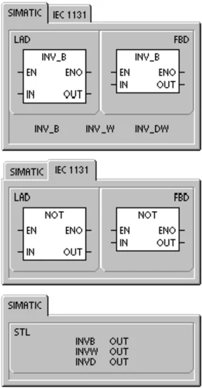
Table 6-51 Valid Operands for the Invert Instructions \begin{tabular}{|l|l|l|} \hline Inputs/Outputs & Data Types & Operands \ \hline IN & BYTE & IB, QB, VB, MB, SMB, SB, LB, AC, *VD, *LD, *AC, Constant \ & WORD & IW, QW, VW, MW, SMW, SW, T, C, LW, AC, AIW, *VD, *LD, *AC, Constant \ & DWORD & ID, QD, VD, MD, SMD, SD, LD, AC, HC, *VD, *LD, *AC, Constant \ \hline OUT & BYTE & IB, QB, VB, MB, SMB, SB, LB, AC, *VD, *LD, *AC \ & WORD & IW, QW, VW, MW, SMW, SW, T, C, LW, AC, *VD, *LD, *AC \ & DWORD & ID, QD, VD, MD, SMD, SD, LD, AC, *VD, *LD, *AC \ \hline \end{tabular}
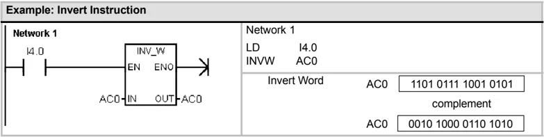
Example: Invert Instruction
161
AND, OR, and Exclusive OR Instructions
AND Byte, AND Word, and AND Double Word
The AND Byte (ANDB), AND Word (ANDW), and AND Double Word (ANDD) instructions AND the corresponding bits of two input values IN1 and IN2 and load the result in a memory location OUT.
OR Byte, OR Word and OR Double Word
The OR Byte (ORB), OR Word instruction (ORW), and OR Double Word (ORD) instructions OR the corresponding bits of two input values IN1 and IN2 and load the result in a memory location OUT.
Exclusive OR Byte, Exclusive OR Word, and Exclusive OR Double Word
The Exclusive OR Byte (XROB), Exclusive OR Word (XORW), and Exclusive OR Double Word (XORD) instruction XOR the corresponding bits of two input values IN1 and IN2 and load the result in a memory location OUT.
SM Bits and ENO
For all of the instructions described on this page, the following conditions affect SM bits and ENO.
Error conditions that set ENO = 0 ■ 0006 (indirect address)
SM bits affected: ■ SM1.0 (zero)
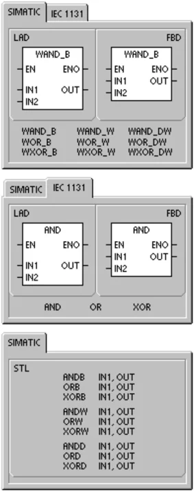
Table 6-52 Valid Operands for the AND, OR, and Exclusive OR Instructions \begin{tabular}{|l|l|l|} \hline Inputs/Outputs & Data Types & Operands \ \hline IN1, IN2 & BYTE & IB, QB, VB, MB, SMB, SB, LB, AC, *VD, *LD, *AC, Constant \ \cline{2-3} & WORD & IW, QW, VW, MW, SMW, SW, T, C, LW, AC, AIW, *VD, *LD, *AC, Constant \ \cline{2-3} & DWORD & ID, QD, VD, MD, SMD, SD, LD, AC, HC, *VD, *LD, *AC, Constant \ \hline OUT & BYTE & IB, QB, VB, MB, SMB, SB, LB, AC, *VD, *AC, *LD \ \cline{2-3} & WORD & IW, QW, VW, MW, SMW, SW, T, C, LW, AC, *VD, *AC, *LD \ \cline{2-3} & DWORD & ID, QD, VD, MD, SMD, SD, LD, AC, *VD, *AC, *LD \ \hline \end{tabular}
S7-200 Instruction Set Chapter 6
Example: AND, OR, and Exclusive OR Instructions
Network 1
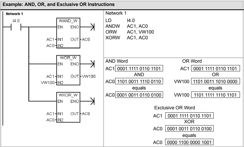
| Network 1 |
|---|
| LD I4.0 |
| ANDW AC1, AC0 |
| ORW AC1, VW100 |
| XORW AC1, AC0 |
AND Word
AC1 0001 1111 0110 1101
AND
AC0 1101 0011 1110 0110
equals
AC0 0001 0011 0110 0100
OR Word
AC1 0001 1111 0110 1101
OR
VW100 1101 0011 1010 0000
equals
VW100 1101 1111 1110 1101
Exclusive OR Word
AC1 0001 1111 0110 1101
XOR
AC0 0001 0011 0110 0100
equals
AC0 0000 1100 0000 1001
163
Move Instructions
Move Byte, Word, Double Word, or Real
The Move Byte (MOVB), Move Word (MOVW), Move Double Word (MOVD), and Move Real (MOVR) instructions move a value from a memory location IN to a new memory location OUT without changing the original value.
Use the Move Double Word instruction to create a pointer. For more information, refer to the section on pointers and indirect addressing in Chapter 4.
For the IEC Move instruction, the input and output data types can vary, but must be of the same size.
Error conditions that set ENO = 0
- 0006 (indirect address)
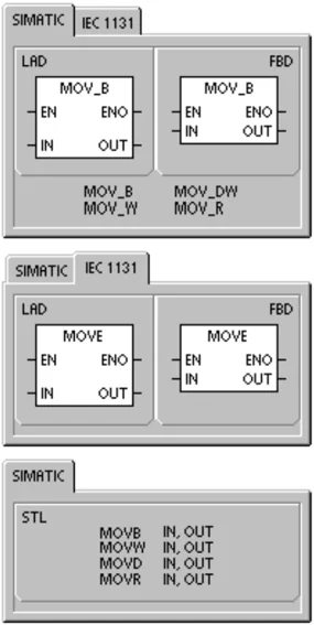
Table 6-53 Valid Operands for the Move Instructions \begin{tabular}{|l|l|l|} \hline Inputs/Outputs & Data Types & Operands \ \hline IN & BYTE & IB, QB, VB, MB, SMB, SB, LB, AC, *VD, *LD, *AC, Constant \ \cline{2-3} & WORD, INT & IW, QW, VW, MW, SMW, SW, T, C, LW, AC, AIW, *VD, *AC, *LD, Constant \ \cline{2-3} & DWORD, DINT & ID, QD, VD, MD, SMD, SD, LD, HC, &VB, &IB, &QB, &MB, &SB, &T, &C, &SMB, &AIW, &AQW, AC, *VD, *LD, *AC, Constant, ID, QD, VD, MD, SMD, SD, LD, AC, *VD, *LD, *AC, Constant \ \hline OUT & BYTE & IB, QB, VB, MB, SMB, SB, LB, AC, *VD, *LD, *AC \ \cline{2-3} & WORD, INT & IW, QW, VW, MW, SMW, SW, T, C, LW, AC, AQW, *VD, *LD, *AC \ \cline{2-3} & DWORD, DINT, REAL & ID, QD, VD, MD, SMD, SD, LD, AC, *VD, *LD, *AC \ \hline \end{tabular}
Move Byte Immediate (Read and Write)
The Move Byte Immediate instructions allow you to immediately move a byte between the physical I/O and a memory location.
The Move Byte Immediate Read (BIR) instruction reads physical input (IN) and writes the result to the memory address (OUT), but the process-image register is not updated.
The Move Byte Immediate Write instruction (BIW) reads the data from the memory address (IN) and writes to physical output (OUT), and the corresponding process image location.
Error conditions that set ENO = 0
- 0006 (indirect address)
- Unable to access expansion module
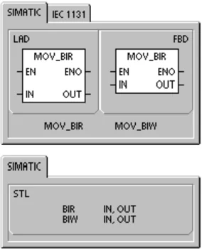
Table 6-54 Valid Operands for the Move Byte Immediate Read Instruction \begin{tabular}{|l|l|l|} \hline Inputs/Outputs & Data Types & Operands \ \hline IN & BYTE & IB, *VD, *LD, *AC \ \hline OUT & BYTE & IB, QB, VB, MB, SMB, SB, LB, AC, *VD, *LD, *AC \ \hline \end{tabular}
Table 6-55 Valid Operands for the Move Byte Immediate Write Instruction \begin{tabular}{|l|l|l|} \hline Inputs/Outputs & Data Types & Operands \ \hline IN & BYTE & IB, QB, VB, MB, SMB, SB, LB, AC, *VD, *LD, *AC, Constant \ \hline OUT & BYTE & QB, *VD, *LD, *AC \ \hline \end{tabular}
Block Move Instructions
Block Move Byte, Word, or Double Word
The Block Move Byte (BMB), Block Move Word (BMW), and Block Move Double Word (BMD) instructions move a specified amount of data to a new memory location by moving the number of bytes, words, or double words N starting at the input address IN to a new block starting at the output address OUT.
N has a range of 1 to 255.
Error conditions that set ENO = 0
- 0006 (indirect address)
- 0091 (operand out of range)
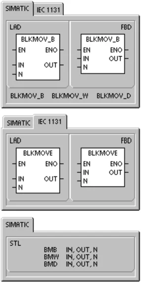
Table 6-56 Valid Operands for the Block Move Instructions \begin{tabular}{|l|l|l|} \hline Inputs/Outputs & Data Types & Operands \ \hline IN & BYTE & IB, QB, VB, MB, SMB, SB, LB, *VD, *LD, *AC \ & WORD, INT & IW, QW, VW, MW, SMW, SW, T, C, LW, AIW, *VD, *LD, *AC \ & DWORD, DINT & ID, QD, VD, MD, SMD, SD, LD, *VD, *LD, *AC \ \hline OUT & BYTE & IB, QB, VB, MB, SMB, SB, LB, *VD, *LD, *AC \ & WORD, INT & IW, QW, VW, MW, SMW, SW, T, C, LW, AQW, *VD, *LD, *AC \ & DWORD, DINT & ID, QD, VD, MD, SMD, SD, LD, *VD, *LD, *AC \ \hline N & BYTE & IB, QB, VB, MB, SMB, SB, LB, AC, Constant, *VD, *LD, *AC \ \hline \end{tabular}
Example: Block Move Instruction
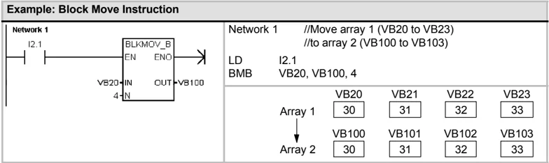
Network 1 //Move array 1 (VB20 to VB23) //to array 2 (VB100 to VB103) LD I2.1 BMB VB20, VB100, 4
Array 1 VB20 30 VB21 31 VB22 32 VB23 33
Array 2 VB100 30 VB101 31 VB102 32 VB103 33
166
Program Control Instructions
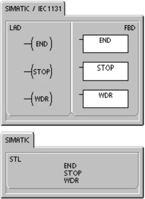
Conditional End
The Conditional End instruction (END) terminates the current scan based upon the condition of the preceding logic. You can use the Conditional End instruction in the main program, but you cannot use it in either subroutines or interrupt routines.
Stop
The Stop instruction (STOP) terminates the execution of your program by causing a transition of the S7-200 CPU from RUN to STOP mode.
If the Stop instruction is executed in an interrupt routine, the interrupt routine is terminated immediately, and all pending interrupts are ignored. Remaining actions in the current scan cycle are completed, including execution of the main user program, and the transition from RUN to STOP mode is made at the end of the current scan.
Watchdog Reset
The Watchdog Reset instruction (WDR) retriggers the system watchdog timer of the S7-200 CPU to extend the time that the scan is allowed to take without getting a watchdog error.
You should use the Watchdog Reset instruction carefully. If you use looping instructions either to prevent scan completion or to delay excessively the completion of the scan, the following processes are inhibited until the scan cycle is completed:
☐ Communications (except Freeport Mode) ☐ I/O updating (except Immediate I/O) ☐ Force updating ☐ SM bit updating (SM0, SM5 to SM29 are not updated) ☐ Run-time diagnostics ☐ 10-ms and 100-ms timers will not properly accumulate time for scans exceeding 25 seconds ☐ STOP instruction, when used in an interrupt routine ☐ Expansion modules with discrete outputs also include a watchdog timer that turns off outputs if the module is not written by the S7-200. Use an immediate write to each expansion module with discrete outputs to keep the correct outputs on during extended scan times. Refer to the example that follows this description.
Tip If you expect your scan time to exceed 500 ms, or if you expect a burst of interrupt activity that could prevent returning to the main scan for more than 500 ms, you should use the Watchdog Reset instruction to retrigger the watchdog timer.
Each time you use the Watchdog Reset instruction, you should also use an immediate write to one output byte (QB) in each discrete expansion module to reset each expansion module watchdog.
If you use the Watchdog Reset instruction to allow the execution of a program that requires a long scan time, changing the mode switch to the STOP position causes the S7-200 to transition to STOP mode within 1.4 seconds.
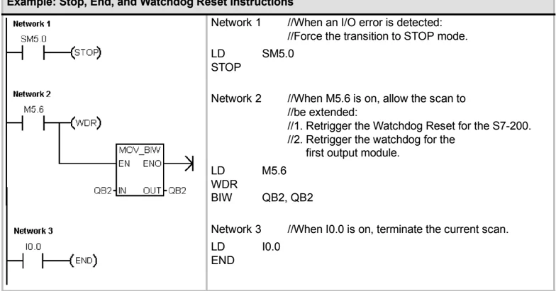
Example: Stop, End, and Watchdog Reset Instructions
168
For-Next Loop Instructions
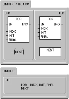
Use the For (FOR) and Next (NEXT) instructions to delineate a loop that is repeated for the specified count. Each For instruction requires a Next instruction. You can nest For-Next loops (place a For-Next loop within a For-Next loop) to a depth of eight.
The For instruction executes the instructions between the For and the Next instructions. You specify the index value or current loop count INDX, the starting value INIT, and the ending value FINAL.
The Next instruction marks the end of the FOR loop.
Error conditions that set ENO = 0 ■ 0006 (indirect address)
If you enable the For-Next loop, it continues the looping process until it finishes the iterations, unless you change the final value from within the loop itself. You can change the values while the For-Next loop is in the looping process. When the loop is enabled again, it copies the initial value into the index value (current loop number).
The For-Next instruction resets itself the next time it is enabled.
For example, given an INIT value of 1 and a FINAL value of 10, the instructions between the For instruction and the Next instruction are executed 10 times with the INDX value being incremented:
1, 2, 3, ...10.
If the starting value is greater than the final value, the loop is not executed. After each execution of the instructions between the For instruction and the Next instruction, the INDX value is incremented and the result is compared to the final value. If the INDX is greater than the final value, the loop is terminated.
If the top of stack is 1 when your program enters the For-Next loop, then the top of stack will be 1 when your program exits the For-Next loop.
Table 6-57 Valid Operands for the For and Next Instructions \begin{tabular}{|l|l|l|} \hline Inputs/Outputs & Data Types & Operands \ \hline INDX & INT & IW, QW, VW, MW, SMW, SW, T, C, LW, AC, *VD, *LD, *AC \ \hline INIT, FINAL & INT & VW, IW, QW, MW, SMW, SW, T, C, LW, AC, AIW, *VD, *LD, *AC, Constant \ \hline \end{tabular}
Example: For-Next Loop Instructions
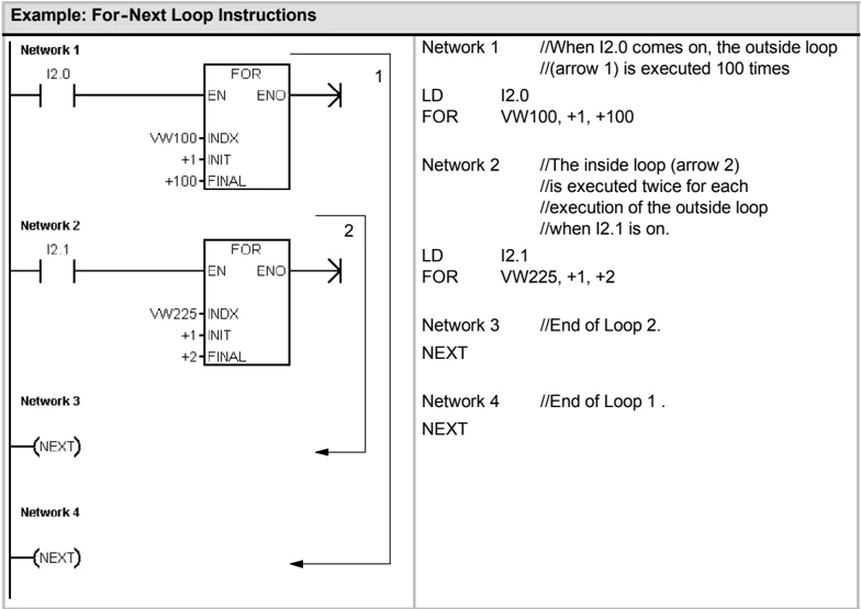
Network 1 //When I2.0 comes on, the outside loop // (arrow 1) is executed 100 times LD I2.0 FOR VW100, +1, +100
Network 2 //The inside loop (arrow 2) //is executed twice for each //execution of the outside loop //when I2.1 is on. LD I2.1 FOR VW225, +1, +2
Network 3 //End of Loop 2. NEXT
Network 4 //End of Loop 1. NEXT
170
S7-200 Instruction Set Chapter 6
J ump Instructions
The J ump to Label instruction (J MP) performs a branch to the specified label N within the program.
The Label instruction (LBL) marks the location of the jump destination N.
You can use the J ump instruction in the main program, in subroutines, or in interrupt routines. The J ump and its corresponding Label instruction must always be located within the same segment of code (either the main program, a subroutine, or an interrupt routine).
You cannot jump from the main program to a label in either a subroutine or an interrupt routine. Likewise, you cannot jump from a subroutine or interrupt routine to a label outside that subroutine or interrupt routine.
You can use a J ump instruction within an SCR segment, but the corresponding Label instruction must be located within the same SCR segment.
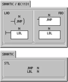
Table 6-58 Valid Operands for the J ump Instructions \begin{tabular}{|l|l|l|} \hline Inputs/Outputs & Data Types & Operands \ \hline N & WORD & Constant (0 to 255) \ \hline \end{tabular}
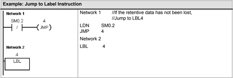
Example: J ump to Label Instruction
171
Sequence Control Relay (SCR) Instructions
SCR instructions provide you with a simple yet powerful state control programming technique that fits naturally into a LAD, FBD, or STL program.
Whenever your application consists of a sequence of operations that must be performed repetitively, SCRs can be used to structure your program so that it corresponds directly to your application. As a result, you can program and debug your application more quickly and easily.
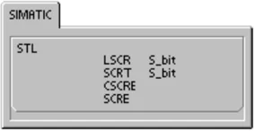
The Load SCR instruction (LSCR) loads the SCR and logic stacks with the value of the S bit referenced by the instruction N.
The SCR segment is energized or de-energized by the resulting value of the SCR stack. The value of the SCR stack is copied to the top of the logic stack so that boxes or output coils can be tied directly to the left power rail without an intervening contact.
Restrictions
When using SCRs, be aware of the following restrictions:
You cannot use the same S bit in more than one routine. For example, if you use S0.1 in the main program, do not use it in a subroutine.
You cannot jump into or out of an SCR segment; however, you can use Jump and Label instructions to jump around SCR segments or to jump within an SCR segment.
You cannot use the END instruction in an SCR segment.
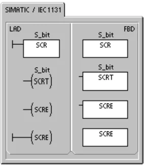
Table 6-59 Valid Operands for the Sequence Control Relay Instructions
S7-200 Instruction Set Chapter 6
Figure 6-31 shows the S stack and the logic stack and the effect of executing the Load SCR instruction. The following is true of S equence Control Relay instructions:
The Load SCR instruction (LSCR) marks the beginning of an SCR segment, and the SCR End instruction (SCRE) marks the end of an SCR segment. All logic between the Load SCR and the SCR End instructions are dependent upon the value of the S stack for its execution. Logic between the SCR End and the next Load SCR instruction is not dependent on the value of the S stack.
The SCR Transition instruction (SCRT) provides the means to transfer control from an active SCR segment to another SCR segment.
Execution of the SCR Transition instruction when it has power flow will reset the S bit of the currently active segment and will set the S bit of the referenced segment. Resetting the S bit of the active segment does not affect the S stack at the time the SCR Transition instruction executes. Consequently, the SCR segment remains energized until it is exited.
Load the value of Sx,y onto the SCR and logic stacks.
 Figure 6-31 Effect of LSCR on the Logic Stack
The Conditional SCR End instruction (CSCRE) provides a means to exit an active SCR segment without executing the instructions between the Conditional SCR End and the SCR End instructions. The Conditional SCR End instruction does not affect any S bit nor does it affect the S stack.
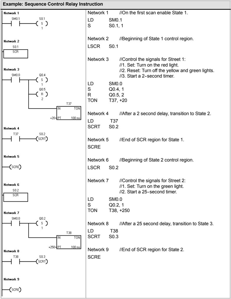
In the following example, the first scan bit SM0.1 sets S0.1, which will be the active State 1 on the first scan. After a 2-second delay, T37 causes a transition to State 2. This transition deactivates the State 1 SCR (S0.1) segment and activates the State 2 SCR (S0.2) segment.
S7-200 Programmable Controller System Manual
Example: Sequence Control Relay Instruction
| Network 1 | Network 1 //On the first scan enable State 1. |
|---|---|
| SM0.1 | LD S M0.1 |
| S0.1 | S S 0.1, 1 |
| Network 2 | Network 2 //Beginning of State 1 control region. |
| S0.1 | LSCR S 0.1 |
| SCR | |
| Network 3 | Network 3 //Control the signals for Street 1: |
| SM0.0 | //1. Set: Turn on the red light. |
| Q0.4 | //2. Reset: Turn off the yellow and green lights. |
| Q0.5 | //3. Start a 2-second timer. |
| LD S M0.0 | |
| S Q0.4, 1 | |
| R Q0.5, 2 | |
| TON T37, +20 | |
| Network 4 | Network 4 //After a 2 second delay, transition to State 2. |
| T37 | LD T37 |
| S0.2 | SCRT S 0.2 |
| Network 5 | Network 5 //End of SCR region for State 1. |
| SCRE | |
| Network 5 | Network 6 //Beginning of State 2 control region. |
| LSCR S 0.2 | |
| Network 6 | Network 7 //Control the signals for Street 2: |
| S0.2 | //1. Set: Turn on the green light. |
| SCR | //2. Start a 25-second timer. |
| LD S M0.0 | |
| S Q0.2, 1 | |
| TON T38, +250 | |
| Network 7 | Network 8 //After a 25 second delay, transition to State 3. |
| SM0.0 | LD T38 |
| Q0.2 | SCRT S 0.3 |
| Network 8 | Network 9 //End of SCR region for State 2. |
| T38 | SCRE |
| S0.3 | |
| Network 9 | |
174
S7-200 Instruction Set Chapter 6
Divergence Control
In many applications, a single stream of sequential states must be split into two or more different streams. When a control stream diverges into multiple streams, all outgoing streams must be activated simultaneously. This is shown in Figure 6-32.
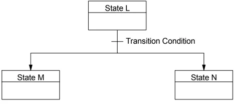
Figure 6-32 Divergence of a Control Stream
The divergence of control streams can be implemented in an SCR program by using multiple SCRT instructions enabled by the same transition condition, as shown in the following example.
Example: Divergence of Control Streams \begin{tabular}{ll} \textbf{Network 1} & Network 1 \quad //Beginning of State L control region. \ S3.4 & LSCR S3.4 \ SCR & \ & Network 2 \ \textbf{Network 2} & LD M2.3 \ M2.3 I2.1 S3.5 & A I2.1 \ (SCRT) & SCRT S3.5 \quad //Transition to State M \ & SCRT S6.5 \quad //Transition to State N \ & Network 3 \quad //End of the State region for State L. \ \textbf{Network 3} & SCRE \ (SCRE) & \ \end{tabular}
Convergence Control
A situation similar to divergence control arises when two or more streams of sequential states must be merged into a single stream. When multiple streams merge into a single stream, they are said to converge. When streams converge, all incoming streams must be complete before the next state is executed. Figure 6-33 depicts the convergence of two control streams.
The convergence of control streams can be implemented in an SCR program by making the transition from state L to state L' and by making the transition from state M to state M'. When both SCR bits representing L' and M' are true, state N can the enabled as shown in the following example.
175
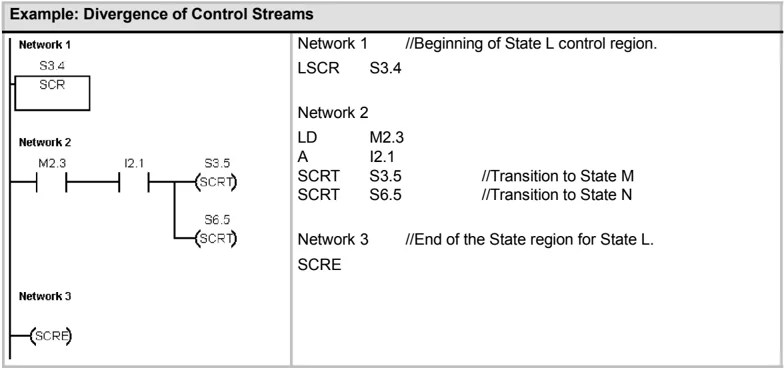
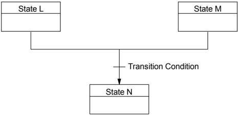
Figure 6-33 Convergence of a Control Stream
Example: Convergence of Control Streams
| Network 1 | Network 1 //Beginning of State L control region |
|---|---|
| S3.4 | LSCR S3.4 |
| SCR | |
| Network 2 | Network 2 //Transition to State L' |
| V100.5 S3.5 | LD V100.5 |
| (SCRT) | SCRT S3.5 |
| Network 3 | Network 3 //End of SCR region for State L |
| (SCRE) | SCRE |
| Network 4 | Network 4 //Beginning of State M control region |
| S6.4 | LSCR S6.4 |
| SCR | |
| Network 5 | Network 5 //Transition to State M' |
| C50 S6.5 | LD C50 |
| (SCRT) | SCRT S6.5 |
| Network 6 | Network 6 //End of SCR region for State M |
| (SCRE) | SCRE |
| Network 7 | Network 7 //When both State L' and State M' |
| //are activated: | |
| //1. Enable State N (S5.0) | |
| //2. Reset State L' (S3.5) | |
| //3. Reset State M' (S6.5) | |
| S3.5 S6.5 S5.0 | LD S3.5 |
| ( S ) | A S6.5 |
| 1 | S S5.0, 1 |
| S3.5 | R S3.5, 1 |
| ( R ) | R S6.5, 1 |
| 1 | |
| S6.5 | |
| ( R ) | |
| 1 |
176
S7-200 Instruction Set Chapter 6
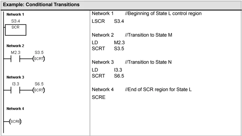
In other situations, a control stream might be directed into one of several possible control streams, depending upon which transition condition comes true first. Such a situation is depicted in Figure 6-34, which shows an equivalent SCR program.
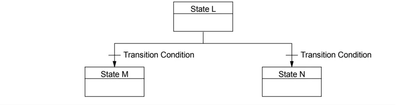
Figure 6-34 Divergence of a Control Stream, Depending on the Transition Condition
Example: Conditional Transitions
| Network 1 | Network 1 //Beginning of State L control region |
|---|---|
| S3.4 | LSCR S3.4 |
| SCR | |
| Network 2 | Network 2 //Transition to State M |
| M2.3 S3.5 | LD M2.3 |
| (SCRT) | SCRT S3.5 |
| Network 3 | Network 3 //Transition to State N |
| I3.3 S6.5 | LD I3.3 |
| (SCRT) | SCRT S6.5 |
| Network 4 | Network 4 //End of SCR region for State L |
| (SCRE) | SCRE |
177
Diagnostic LED Instruction
If the input parameter IN has a value of zero, then set the diagnostic LED OFF. If the input parameter IN has a value greater than zero, then set the diagnostic LED ON (yellow).
The CPU light emitting diode (LED) labeled SF/DIAG can be configured to indicate yellow when either the conditions specified in the System Block are true or when the DIAG_LED instruction is executed with a non-zero IN parameter.
System Block (Configure LED) check box options:
- SF/DIAG LED is ON (yellow) when an item is forced in the CPU
- SF/DIAG LED is ON (yellow) when a module has an I/O error
Uncheck both Configure LED options to give the DIAG_LED instruction sole control over SF/DIAG yellow illumination. A CPU System Fault (SF) is indicated with red illumination.
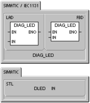
Table 6-60 Valid Operands for the Diagnostic LED Instruction \begin{tabular}{|l|l|l|} \hline Inputs/Outputs & Data Types & Operands \ \hline IN & BYTE & VB, IB, QB, MB, SB, SMB, LB, AC, Constant, *VD, *LD, *AC \ \hline \end{tabular}
Example 1 Diagnostic LED Instruction Blink the diagnostic LED when an error is detected. Blink the diagnostic LED any time one of the 5 error conditions is detected.
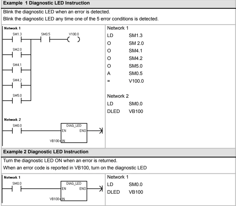
Example 2 Diagnostic LED Instruction Turn the diagnostic LED ON when an error is returned. When an error code is reported in VB100, turn on the diagnostic LED
Shift and Rotate Instructions
Shift Right and Shift Left Instructions
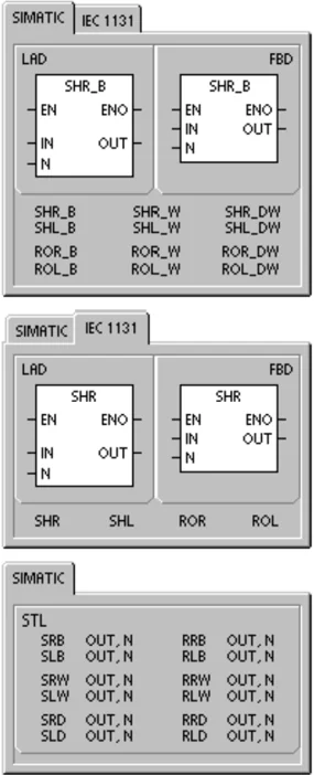
The Shift instructions shift the input value IN right or left by the shift count N and load the result in the output OUT.
The Shift instructions fill with zeros as each bit is shifted out. If the shift count (N) is greater than or equal to the maximum allowed (8 for byte operations, 16 for word operations, and 32 for double word operations), the value is shifted the maximum number of times for the operation. If the shift count is greater than 0, the overflow memory bit (S M1.1) takes on the value of the last bit shifted out. The zero memory bit (S M1.0) is set if the result of the shift operation is zero.
Byte operations are unsigned. For word and double word operations, the sign bit is shifted when you use signed data types.
Error conditions that set ENO = 0 ■ 0006 (indirect address)
SM bits affected: ■ S M1.0 (zero) ■ S M1.1 (overflow)
Rotate Right and Rotate Left Instructions
The Rotate instructions rotate the input value (IN) right or left by the shift count (N) and load the result in the memory location (OUT). The rotate is circular.
If the shift count is greater than or equal to the maximum for the operation (8 for a byte operation, 16 for a word operation, or 32 for a double-word operation), the S7-200 performs a modulo operation on the shift count to obtain a valid shift count before the rotation is executed. This result is a shift count of 0 to 7 for byte operations, 0 to 15 for word operations, and 0 to 31 for double-word operations.
If the shift count is 0, a rotate operation is not performed. If the rotate operation is performed, the value of the last bit rotated is copied to the overflow bit (S M1.1).
If the shift count is not an integer multiple of 8 (for byte operations), 16 (for word operations), or 32 (for double-word operations), the last bit rotated out is copied to the overflow memory bit (S M1.1). The zero memory bit (S M1.0) is set when the value to be rotated is zero.
Byte operations are unsigned. For word and double word operations, the sign bit is shifted when you use signed data types.
Error conditions that set ENO = 0 ■ 0006 (indirect address)
SM bits affected: ■ S M1.0 (zero) ■ S M1.1 (overflow)
Table 6-61 Valid Operands for the Shift and Rotate Instructions
\begin{tabular}{|l|l|l|} \hline Inputs/Outputs & Data Types & Operands \ \hline IN & BYTE & IB, QB, VB, MB, SMB, SB, LB, AC, *VD, *LD, *AC, Constant \ \cline{2-3} & WORD & IW, QW, VW, MW, SMW, SW, T, C, LW, AC, AIW, *VD, *LD, *AC, Constant \ \cline{2-3} & DWORD & ID, QD, VD, MD, SMD, SD, LD, AC, HC, *VD, *LD, *AC, Constant \ \hline OUT & BYTE & IB, QB, VB, MB, SMB, SB, LB, AC, *VD, *LD, *AC \ \cline{2-3} & WORD & IW, QW, VW, MW, SMW, SW, T, C, LW, AC, *VD, *LD, *AC \ \cline{2-3} & DWORD & ID, QD, VD, MD, SMD, SD, LD, AC, *VD, *LD, *AC \ \hline N & BYTE & IB, QB, VB, MB, SMB, SB, LB, AC, *VD, *LD, *AC, Constant \ \hline \end{tabular}
S7-200 Programmable Controller System Manual
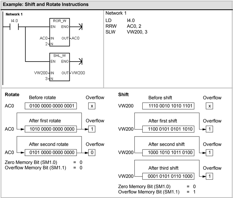
Example: Shift and Rotate Instructions
Network 1
I4.0 ┌───┐ │ │ └───┘ │ ▼ ┌───────┐ │ ROR_W │ │ EN │ │ ENO │ │ IN │ │ OUT │ └───────┘ │ │ │ ▼ │ AC0 │ ▼ ┌───────┐ │ SHL_W │ │ EN │ │ ENO │ │ IN │ │ OUT │ └───────┘ │ │ │ ▼ │ VW200 │ ▼ VW200
Network 1
LD I4.0 RRW AC0, 2 SLW VW200, 3
Rotate
Before rotate
- AC0:
0100 0000 0000 0001 - Overflow:
x
After first rotate
- AC0:
1010 0000 0000 0000 - Overflow:
1
After second rotate
- AC0:
0101 0000 0000 0000 - Overflow:
0
Zero Memory Bit (SM1.0) = 0
Overflow Memory Bit (SM1.1) = 0
Shift
Before shift
- VW200:
1110 0010 1010 1101 - Overflow:
x
After first shift
- VW200:
1100 0101 0101 1010 - Overflow:
1
After second shift
- VW200:
1000 1010 1011 0100 - Overflow:
1
After third shift
- VW200:
0001 0101 0110 1000 - Overflow:
1
Zero Memory Bit (SM1.0) = 0
Overflow Memory Bit (SM1.1) = 1
180
Shift Register Bit Instruction
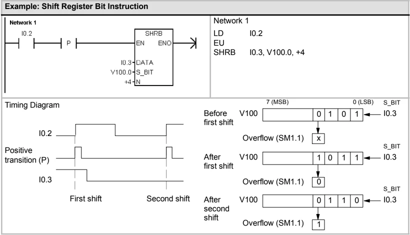
The Shift Register Bit instruction shifts a value into the Shift Register. This instruction provides an easy method for sequencing and controlling product flow or data. Use this instruction to shift the entire register one bit, once per scan.
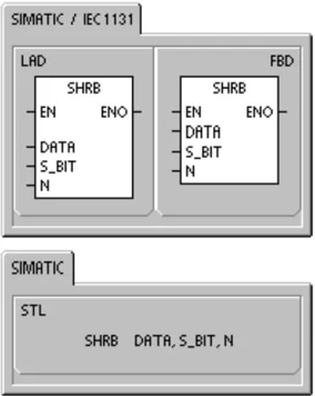
The Shift Register Bit instruction shifts the value of DATA into the Shift Register. S_BIT specifies the least significant bit of the Shift Register. N specifies the length of the Shift Register and the direction of the shift (Shift Plus = N, Shift Minus = -N).
Each bit shifted out by the SHRB instruction is placed in the overflow memory bit (SM1.1).
This instruction is defined by both the least significant bit (S_BIT) and the number of bits specified by the length (N).
Error conditions that set ENO = 0
- 0006 (indirect address)
- 0091 (operand out of range)
- 0092 (error in count field)
SM bits affected:
- SM1.1 (overflow)
Table 6-62 Valid Operands for the Shift Register Bit Instruction
Use the following equation to compute the address of the most significant bit of the Shift R egister (MS B.b):
MS B.b = [(Byte of S_BIT) + ([N] - 1 + (bit of S_BIT)) / 8].[remainder of the division by 8]
For example: if S_BIT is V33.4 and N is 14, the following calculation shows that the MS B.b is V35.1.
MS B.b = V33 + ([14] - 1 +4)/8 = V33 + 17/8 = V33 + 2 with a remainder of 1 = V35.1
On a Shift Minus, indicated by a negative value of length (N), the input data shifts into the most significant bit of the Shift R egister, and shifts out of the least significant bit (S_BIT). The data shifted out is then placed in the overflow memory bit (SM1.1).
On a Shift Plus, indicated by a positive value of length (N), the input data (DATA) shifts into the least significant bit of the Shift R egister, specified by the S_BIT, and out of the most significant bit of the S hift R egister. The data shifted out is then placed in the overflow memory bit (SM1.1).
The maximum length of the shift register is 64 bits, positive or negative. Figure 6-35 shows bit shifting for negative and positive values of N.
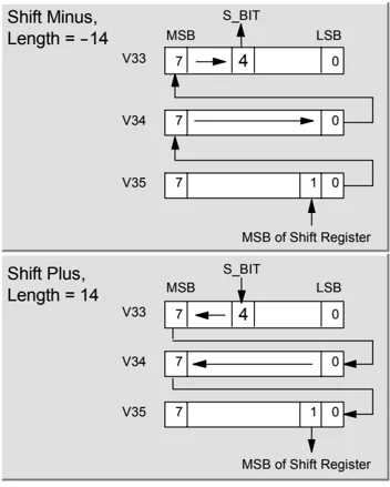
Figure 6-35 Shift R egister Entry and Exit
Example: Shift Register Bit Instruction
| Network 1 | Network 1 |
|---|---|
| LD I0.2EUSHRB I0.3, V100.0, +4 |
Timing Diagram
182
S7-200 Instruction Set Chapter 6
Swap Bytes Instruction
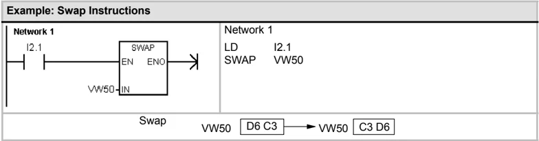
The Swap Bytes instruction exchanges the most significant byte with the least significant byte of the word IN.
Error conditions that set ENO = 0 ■ 0006 (indirect address)
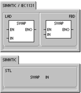
Table 6-63 Valid Operands for the Swap Bytes Instruction \begin{tabular}{|l|l|l|} \hline Inputs/Outputs & Data Types & Operands \ \hline IN & WORD & IW, QW, VW, MW, SMW, SW, T, C, LW,AC, *VD, *LD, *AC \ \hline \end{tabular}
Example: Swap Instructions Network 1 I2.1 SWAP EN ENO VW50 IN
Network 1 LD I2.1 SWAP VW50
Swap VW50 D6 C3 \rightarrow VW50 C3 D6
183
String Instructions
String Length
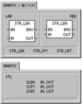
The String Length instruction (SLEN) returns the length of the string specified by IN.
Copy String
The Copy String instruction (SCPY) copies the string specified by IN to the string specified by OUT.
Concatenate String
The Concatenate String instruction (SCAT) appends the string specified by IN to the end of the string specified by OUT.
SM Bits and ENO
For the String Length, Copy String, and Concatenate String instructions, the following conditions affect ENO.
Error conditions that set ENO = 0
- 0006 (indirect address)
- 0091 (range error)
Table 6-64 Valid Operands for the String Length Instruction \begin{tabular}{|l|l|l|} \hline Inputs/Outputs & Data Types & Operands \ \hline IN & STRING & VB, LB, *VD, *LD, *AC, Constant String \ \hline OUT & BYTE & IB, QB, VB, MB, SMB, SB, LB, AC, *VD, *LD, *AC \ \hline \end{tabular}
Table 6-65 Valid Operands for the Copy String and Concatenate String Instructions \begin{tabular}{|l|l|l|} \hline Inputs/Outputs & Data Types & Operands \ \hline IN & STRING & VB, LB, *VD, *LD, *AC, Constant String \ \hline OUT & STRING & VB, LB, *VD, *AC, *LD \ \hline \end{tabular}
S7-200 Instruction Set Chapter 6
Example: Concatenate String, Copy String, and String Length Instructions
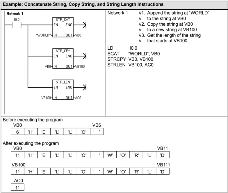
Before executing the program VB0 | 6 | 'H' | 'E' | 'L' | 'L' | 'O' | ' ' | VB6
After executing the program VB0 | 11 | 'H' | 'E' | 'L' | 'L' | 'O' | ' ' | 'W' | 'O' | 'R' | 'L' | 'D' | VB11
VB100 | 11 | 'H' | 'E' | 'L' | 'L' | 'O' | ' ' | 'W' | 'O' | 'R' | 'L' | 'D' | VB111
AC0 | 11 |